PowerHalt is a registered trademark of Pacbrake Co. 1
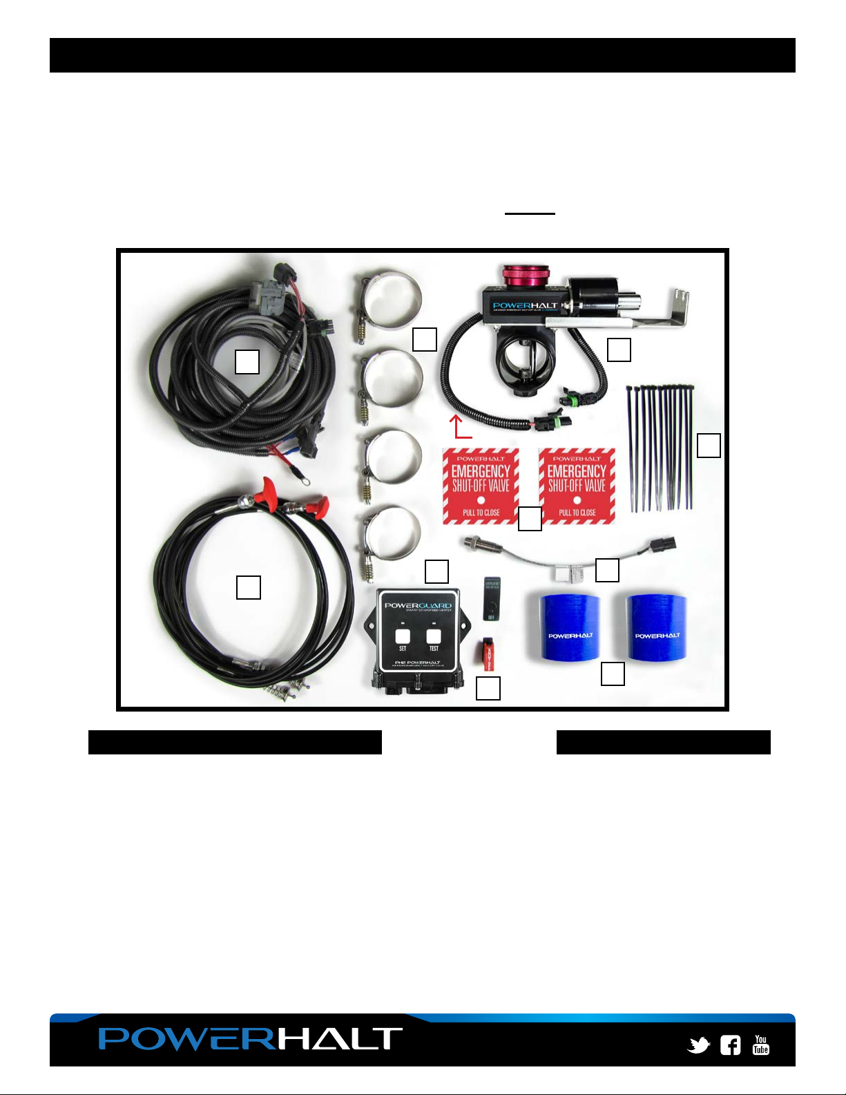
PH2 - AUTO/MANUAL/ELECTRIC WITH PULL CABLE(S) L6372
L6372_REV6.17.04.2018
ECN 1-1859
INSTALLATION REQUIREMENTS & RECOMMENDATIONS:
Prior to the installation, please read through the requirements and recommendations listed below so you have
a clear understanding of your system and the location you plan to install the shut-off valve.
If you cannot meet these requirements, or are unsure of your system, please contact your dealer or PowerHalt
representative and we can work with you to overcome your installation constraints and challenges.
PowerHalt Technical Representative can be reached Monday-Friday 6:00-4:30 (PST) at 800.663.0096
• A 1" clearance is required from the valve to any other components. The valve can be in any orientation.
• Maximum air temperature at the valve should not exceed 120°C. On a turbo-charged engine,
‘Option B’ (see diagram below) should be the last option due to high temperatures. (There are special
options available for higher temperatures, contact Pacbrake).
• Allhoses,adapters,andttingsmustbesuitableforthevibrationoftheengineapplication,
and of reinforced type. *If unsure of your vibration requirement, contact Pacbrake.
• Flexible hose gaps should be kept to a minimum and the overall pipe quality and integrity
fromtheshut-offvalvetotheintakemanifoldshouldbeconrmed.
NOTE: - Failure to ensure this may result in hose collapse during valve activation and
possible system leaks, preventing engine shutdown
- For excessive vibration applications, and installations with long pipe runs,
additional support brackets may be required.
• Ifanairintakeametrapisused,thevalvemustbeinstalledupstreamofthetrap.
• Crankcase breather connections in the intake system between the valve and engine
(or in engine intake parts) must be sealed and replaced by an external breather.
• If you need to cut the existing intake piping to allow for the shut-off valve installation, please make sure to
cut the pipe off of the engine and that it is cleaned thoroughly to ensure no shavings are present.
NOTE: Failure to do so may result in engine damage caused by foreign debris ingesting into the engine.
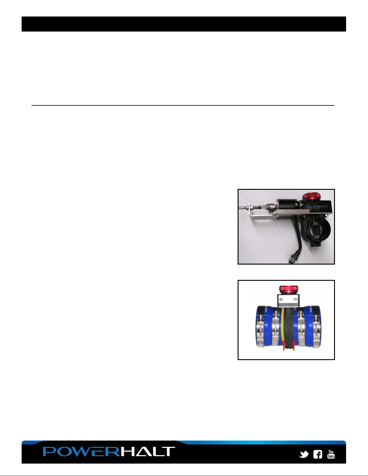
• Itishighlyrecommendedthatthepipeisrolledwithabeadtoensurehosettingretentiononboththeinlet
and outlet sides of the shut-off valve.
• If more than one shut-off valve is installed on one engine it is imperative that the control method is
consistent with this requirement, ensuring valve activation is simultaneous for both valves.
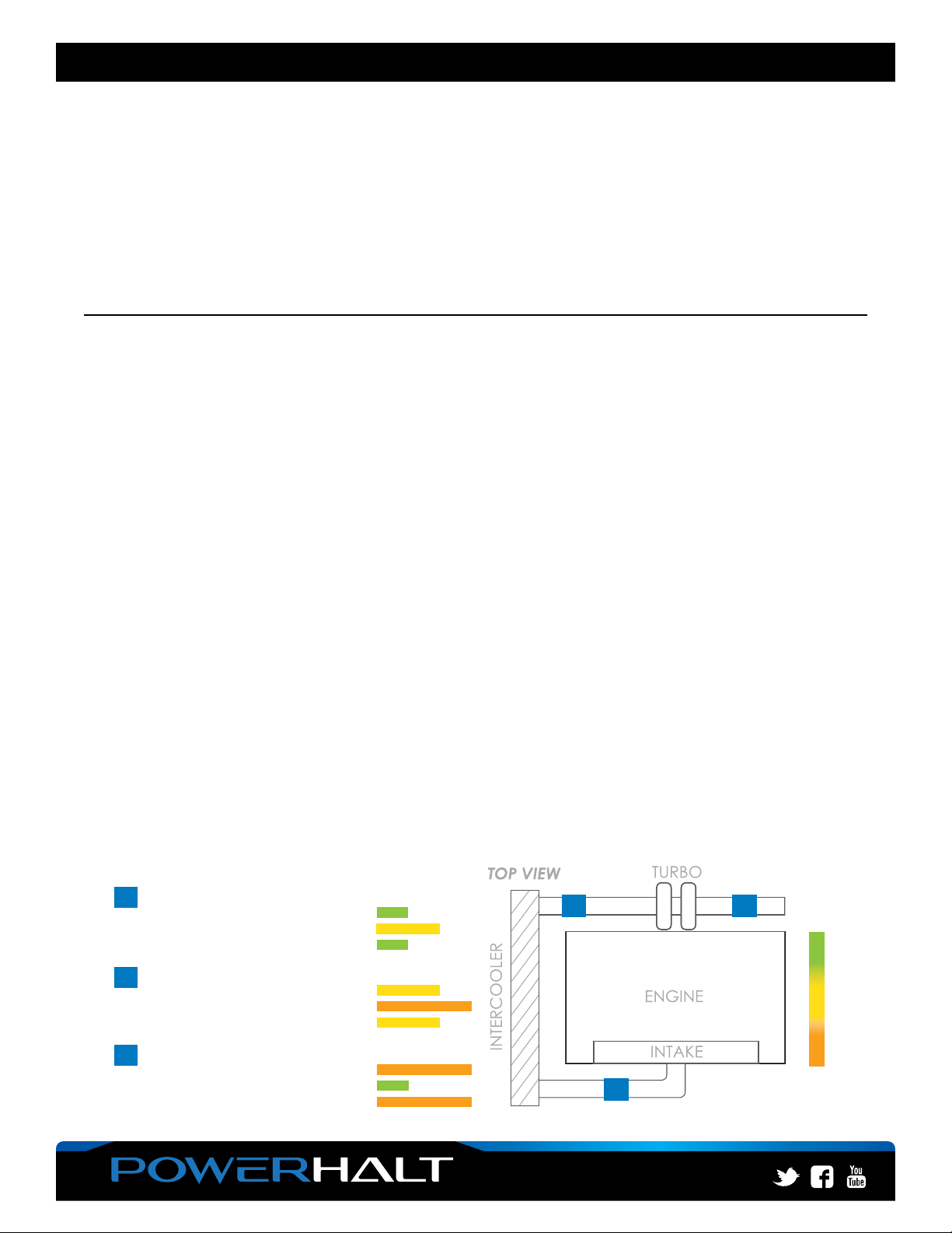
In order of preferred location to least preferred
1
st POST INTERCOOLER
■Low Plumbing Leakage Risk
■Moderate Charge Air Temperature
■Fast Shutdown Response Time
2
nd POST TURBO
■Moderate Plumbing Leakage Risk
■High Charge Air Temperature
■Moderate Shutdown Response Time
3
rd PRE TURBO
■High Plumbing Leakage Risk
■Low Charge Air Temperature
■Slow Shutdown Response Time
1
st
2
nd
3
rd
ACCEPTABLE
(Not recommended)
OPTIMAL
(Recommended)
PERFORMANCE