SAC TURBO-MAX 6090 User manual

QUALITY PEOPLE, QUALITY PRODUCTS
Sioux Automation Center, Inc.• 877 1st Ave NW • Sioux Center, IA 51250
PH: (712-722-1488) • Toll Free: 1-866-722-1488
www.siouxautomation.com
ASSEMBLY
CALIBRATION
OPERATION
REPLACEMENT PARTS
READ COMPLETE MANUAL CAREFULLY
BEFORE ATTEMPTING OPERATION
11/11/10
MON600179
Rev A
TURBO-MAX
6090 TRUCK
OPERATORS MANUAL

Page 2
GENERAL INFORMATION
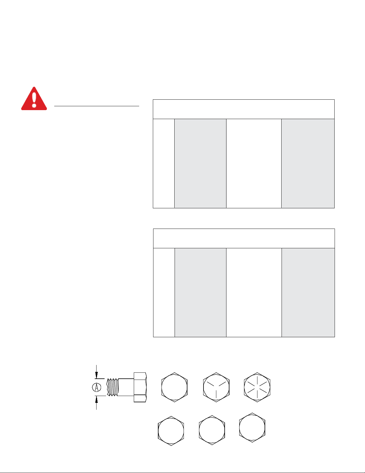
1. Unless otherwise specified, high-strength (grade5)
(3 radial-line head markings) hex head bolts are used
throughout assembly of this piece of equipment.
2. Whenever terms “LEFT” and “RIGHT” are used in this
manual it means from a position behind wagon box and
facing forward.
3. When placing a parts order, refer to this manual for
proper part numbers and place order by PART NO. and
DESCRIPTION.
4. Read assembly instructions carefully. Study
assembly procedures and all illustrations before you begin
assembly. Note which parts are used in each step. This
unit must be assembled in proper sequence or complica-
tions will result.
WARNING: TO AVOID PERSONAL INJURY OR DEATH, OBSERVE FOLLOWING
INSTRUCTIONS:
Never overload mixer. Rating of gear or rating of tires, whichever is less.
Ensure that anybody present is clear before applying power to any machinery used in conjunc-
tion with wagon box or when moving box.
Never allow anyone in, near, or on mixing chamber during mixing, transporting, or unloading
of feed.
Thank you for purchasing a Turbo-Max Mixer Truck. We feel you have made a wise choice and hope you are completely satis-
fi e d with your new piece of equipment. Your new Turbo-Max Mixer Truck is a durable, efficient and easy to use unit. Proper
care and use will result in many years of service.
INTRODUCTION
Table of Contents
General Information ............................................................................................................ 2
Safety , Signal Words. . . . . . . . . . . . . . . . . . . . . . . . . . . . . . . . . . . . . . . . . . . . . . . . . . . . . . . . . . . . . . . . . . . . . . . . . . . . . . . . . . . . . . . . . . . . . . . . . . . . . . . . . . 3
Equipment Safety Guidelines. . . . . . . . . . . . . . . . . . . . . . . . . . . . . . . . . . . . . . . . . . . . . . . . . . . . . . . . . . . . . . . . . . . . . . . . . . . . . . . . . . . . . . . . . . . . . . 4
Lighting and Marking. . . . . . . . . . . . . . . . . . . . . . . . . . . . . . . . . . . . . . . . . . . . . . . . . . . . . . . . . . . . . . . . . . . . . . . . . . . . . . . . . . . . . . . . . . . . . . . . . . . . . . . . . . . 4
Safety Sign Care. . . . . . . . . . . . . . . . . . . . . . . . . . . . . . . . . . . . . . . . . . . . . . . . . . . . . . . . . . . . . . . . . . . . . . . . . . . . . . . . . . . . . . . . . . . . . . . . . . . . . . . . . . . . . . . . . 4
Tire Safety. . . . . . . . . . . . . . . . . . . . . . . . . . . . . . . . . . . . . . . . . . . . . . . . . . . . . . . . . . . . . . . . . . . . . . . . . . . . . . . . . . . . . . . . . . . . . . . . . . . . . . . . . . . . . . . . . . . . . . . . . . . 5
Before Operation. . . . . . . . . . . . . . . . . . . . . . . . . . . . . . . . . . . . . . . . . . . . . . . . . . . . . . . . . . . . . . . . . . . . . . . . . . . . . . . . . . . . . . . . . . . . . . . . . . . . . . . . . . . . . . . . . 5
During Operation. . . . . . . . . . . . . . . . . . . . . . . . . . . . . . . . . . . . . . . . . . . . . . . . . . . . . . . . . . . . . . . . . . . . . . . . . . . . . . . . . . . . . . . . . . . . . . . . . . . . . . . . . . . . . . . . 5-7
Following Operation . . . . . . . . . . . . . . . . . . . . . . . . . . . . . ........................................................ . . . . . . . . . . . . . . . . . . . . . . . 7
Highway and Transport Operations....................................................................................7-8
Performing Maintenance. . . . . . . . . . . . . . . . . . . . . . . . . . . . . . . . . . . . . . . . . . . . . . . . . . . . . . . . . . . . . . . . . . . . . . . . . . . . . . . . . . . . . . . . . . . . . . . . . . . . . 8
Bolt Torque . . . . . . . . . . . . . . . . . . . . . . . . . . . . . . . . . . . . . . . . . . . . . . . . . . . . . . . . . . . . . . . . . . . . . . . . . . . . . . . . . . . . . . . . . . . . . . . . . . . . . . . . . . . . . . . . . . . . . . . . . . 9
Mixer Setup. . . . . . . . . . . . . . . . . . . . . . . . . . . . . . . . . . . . . . . . . . . . . . . . . . . . . . . . . . . . . . . . . . . . . . . . . . . . . . . . . . . . . . . . . . . . . . . . . . . . . . . . . . . . . . . . . . . . . . . . 10
Mixer Operation. . . . . . . . . . . . . . . . . . . . . . . . . . . . . . . . . . . . . . . . . . . . . . . . . . . . . . . . . . . . . . . . . . . . . . . . . . . . . . . . . . . . . . . . . . . . . . . . . . . . . . . . . . . . . . . . 11-12
Inspections and Adjustments ............................................................................................. 13
Lubrication Schedule.......................................................................................................... 14
Decal Location ................................................................................................................... 15
Oilbath Assembly ............................................................................................................... 16
Reel & Auger Assembly...................................................................................................... 17
Final Assembly. . . . . . . . . . . . . . . . . . . . . . . . . . . . . . . . . . . . . . . . . . . . . . . . . . . . . . . . . . . . . . . . . . . . . . . . . . . . . . . . . . . . . . . . . . . . . . . . . . . . . . . . . . . . . . . . . 18-19
Options. . . . . . . . . . . . . . . . . . . . . . . . . . . . . . . . . . . . . . . . . . . . . . . . . . . . . . . . . . . . . . . . . . . . . . . . . . . . . . . . . . . . . . . . . . . . . . . . . . . . . . . . . . . . . . . . . . . . . . . . . . . . . . . 20
Discharge Breakdown
Slide Tray. . . . . . . ............. . . . . . . . .............. . . . . . . . ......... . . . . . . . ............. . . . . . . . ............. . . . . ............. . . . . 21
Slide Tray (used on serial #) ......................................................................................... 21
Hydraulic Breakdown
Electric Selector Valve for Slide Tray......... ............................. .............. ......................... 22
Switchbox Assembly
Toggle Switch Assembly. . . . . . . . . . . . . . . . . . . . . . . . . . . . . . . . . . . . . . . . . . . . . . . . . . . . . . . . . . . . . . . . . . . . . . . . . . . . . . . . . . . . . . . . . . . . . . . . . 23
Joystick Assembly. . . . . . . . . . . . . . . . . . . . . . . . . . . . . . . . . . . . . . . . . . . . . . . . . . . . . . . . . . . . . . . . . . . . . . . . . . . . . . . . . . . . . . . . . . . . . . . . . . . . . . . . . . 23
Driveline Assembly. . . . . . . . . . . . . . . . . . . . . . . . . . . . . . . . . . . . . . . . . . . . . . . . . . . . . . . . . . . . . . . . . . . . . . . . . . . . . . . . . . . . . . . . . . . . . . . . . . . . . . . . . . . 24-25
General Specifications . . . . . . . . . . . . . . . . . . . . . . . . . . . . . . . . . . . . . . . . . . . . . . . . . . . . . . . . . . . . . . . . . . . . . . . . . . . . . . . . . . . . . . . . . . . . . . . . . . . . . . . 26
Warranty. . . . . . . . . . . . . . . . . . . . . . . . . . . . . . . . . . . . . . . . . . . . . . . . . . . . . . . . . . . . . . . . . . . . . . . . . . . . . . . . . . . . . . . . . . . . . . . . . . . . . . . . . . . . . . . . . . . . . . . . . . . 28-29

Page 3
SAFETY, SIGNAL WORDS
SAFETY
TAKE NOTE! THIS SAFETY ALERT SYMBOL FOUND THROUGHOUT THIS
MANUAL IS USED TO CALL YOUR ATTENTION TO INSTRUCTIONS INVOLVING YOUR
PERSONAL SAFETY AND SAFETY OF OTHERS. FAILURE TO FOLLOW THESE
INSTRUCTIONS CAN RESULT IN INJURY OR DEATH!
THIS SYMBOL MEANS
ATTENTION
BECOME ALERT
YOUR SAFETY IS INVOLVED!
SIGNAL WORDS
Note: use of following signal words DANGER, WARNING, and
CAUTION with safety messages. Appropriate signal word for
each has been selected using following guidelines:
DANGER:
Indicates an imminently hazardous situation that, if not
avoided, will result in serious injury or death. This signal
word is to be limited to most extreme situations typically for
machine components which, for functional purposes, cannot
be guarded.
WARNING:
Indicates a potentially hazardous situation that, if not avoided,
could result in serious injury or death, and includes hazards
that are exposed when guards are removed. It may also be
used to alert against unsafe practices.
CAUTION:
Indicates a potentially hazardous situation that, if not avoided,
may result in minor or moderate injury. It may also be used
to alert against unsafe practices.
If you have questions not answered in this manual , require additional copies, or if your manual is damaged, please contact
your dealer or Sioux Automation Center Inc., 877 1st Ave NW, Sioux Center, IA 51250, ph: (712) 722-1488 or
Toll Free: 1-866-722-1488, Fax: (712) 722-1487 http://www.siouxautomation.com

Page 4
SAFETY...YOU CAN LIVE WITH IT
EQUIPMENT SAFETY GUIDELINES
Every year many accidents occur which could have been avoided by a few seconds of thought and a more
careful approach to handling equipment. You, the operator, can avoid many accidents by observing the following
precautions in this section. To avoid personal injury, study the following precautions and insist those working
with you, and you yourself, follow them.
In order to provide a better view, certain illustrations in this manual may show an assembly with a safety shield
removed. However, equipment should never be operated in this condition. Keep all shields in place. If shield
removal becomes necessary for repairs, replace shield prior to use.
Replace any caution, warning, danger or instruction safety decal that is not readable or is missing. Location
of such decals is indicated in this booklet.
Do not attempt to operate this equipment under the influence of alcohol or drugs.
Review safety instructions with all users annually.
Operator should be a responsible adult. DO NOT ALLOW PERSONS TO OPERATE OR ASSEMBLE
THIS UNIT UNTIL THEY HAVE DEVELOPED A THOROUGH UNDERSTANDING OF SAFETY
PRECAUTIONS AND HOW IT WORKS.
Do not paint over, remove, or deface any safety signs or warning decals on your equipment. Observe all
safety signs and practice instructions on them.
Never exceed limits of a piece of machinery. If its ability to do a job, or to do so safely is in question DON’T
TRY IT.
LIGHTING AND MARKING
It is the responsibility of customer to know lighting and marking requirements of local highway authorities and
to install and maintain equipment to provide compliance with regulations. Add extra lights when transporting
at night or during periods of limited visibility.
Lighting kits are available from your dealer or from manufacturer.
SAFETY SIGN CARE
• Keep safety signs clean and legible at all times.
• Replace safety signs that are missing or have become illegible.
• Replaced parts that displayed safety signs should also display current safety signs.
• Safety signs are available from your distributor, dealer parts department, or factory.
How to install safety signs:
• Be sure that installation area is clean and dry.
• Decide on exact position before you remove backing paper.
• Remove smallest portion of split backing paper.
• Align decal over specified area and carefully press small portion with exposed sticky backing in place.
• Slowly peel back remaining paper and carefully smooth remaining portion of decal into place.
• Small air pockets can be pierced with a pin and smoothed out using piece of decal backing paper.

Page 5
TIRE SAFETY
• Failure to follow proper procedures when mounting a tire on a rim can produce an explosion which may
result in a serious injury or death.
• Do not attempt to mount a tire unless you have proper equipment and experience to do job.
• Inflating or servicing tires can be dangerous. Whenever possible, trained personnel should be called to
service and/or mount tires.
• Always order and install tires and wheels with appropriate type and load capacity to meet or exceed
anticipated weight to be placed on the equipment.
REMEMBER
Your best assurance against accidents is a careful and responsible operator. If there is any portion of this
manual or function you do not understand, contact your local authorized dealer or manufacturer.
BEFORE OPERATION:
• Carefully study and understand this manual.
• Do not wear loose-fitting clothing which may catch in moving parts.
• Always wear protective clothing and substantial shoes.
• It is recommended that suitable hearing and eye protection be worn.
• Operator may come in contact with certain materials which may require specific safety equipment relative to
handling of such materials.
• Keep wheel and lug nuts tightened to specified torque.
• Assure that truck tires are inflated evenly.
• Give unit a visual inspection for any loose bolts, worn parts, or cracked welds, and make necessary repairs.
Follow maintenance safety instructions included in this manual.
• Be sure there are no tools lying on or in equipment
• Do not use unit until you are sure that area is clear, especially around children and animals.
• Don’t hurry learning process or take unit for granted. Ease into it and become familiar with your new equipment.
• Practice operation of your equipment and its attachments. Completely familiarize yourself and other operators
with its operation before using.
• Make sure that brakes are evenly adjusted (if equipped with brakes).
• Fasten your seat belt prior to starting the engine.
DURING OPERATION
• Beware of bystanders, PARTICULARLY CHILDREN! Always look around to make sure that it is safe to
start engine of towing vehicle or move unit. This is particularly important with higher noise levels and quiet cabs,
asyou may not hear people shouting.
• NO PASSENGERS ALLOWED- Do not carry passengers anywhere on or in tractor or equipment.

Page 6
DURING OPERATION
• Keep hands and clothing clear of moving parts.
• Do not clean, lubricate, or adjust your equipment while it is moving.
• When halting operation, even periodically, set vehicle brakes, disengage PTO, shut off
engine, and remove ignition key.
• Be especially observant of operating area and terrain. Watch for holes, rocks, or other hidden hazards. Always
inspect area prior to operation.
- DO NOT operate near edge of drop-off or banks.
- DO NOT operate on steep slopes as overturn may result.
- Operate up and down (not across) intermediate slopes. Avoid sudden starts and stops.
• Pick the most level possible route when transporting across fields. Avoid edges of ditches, gullies, and steep
hillsides.
• Be extra careful when working on inclines.
• Maneuver truck at safe speeds.
• Avoid overhead wires or other obstacles. Contact with overhead lines could cause serious injury or death.
• Avoid loose gravel, rocks, and holes; they can be dangerous for equipment operation or
movement.
• Allow for unit length when making turns.
• Do not walk or work under raised components or attachments unless securely positioned and blocked.
• Keep all bystanders, pets, and livestock clear of work area.
• Operate towing vehicle from operators seat only.
• Never stand alongside of unit with engine running or attempt to start engine and/or operate machine while
standing alongside of unit.
• Never leave running equipment unattended.
• As a precaution, always recheck hardware on equipment following every 100 hours of operation. Correct all
problems. Follow maintenance safety procedures.
• Never hand feed materials into mixer while it is running. Rotating augers inside mixer may not be visible from
the loading point, and may cut or grab hands, clothing, or material being loaded, causing severe injury.
Always stop tractor engine before hand loading materials.
• No not allow operation of this unit by inexperienced or unqualified people. Keep all unqualifed people away
from mixer during operation. Operators of this unit must be alert and use good judgement at all times. Operator
should not climb on ladder or any part of the mixer when loading, mixing, or discharging material.
• Be sure the inside of the mixer is clear of any obstruction before operating and that all shields are in place. This
includes any truck and driveline shields. Repair or replace any damaged or missing shielding. Exposed shafting
can grab hands and clothing and cuase severe injury or death.

Page 7
• Use caution when working around the discharge area. Stay clear of slide tray. This is controlled from the truck
and could operate without warning, creating pinch points which could cause severe injury or death. Always
disengage the PTO, stop the truck’s engine and remove the truck’s egnition key before working close to the
discharge area.
• Never attempt to release jammed materials or clean materials from any area of the mixer or discharge chute with
out disengaging the PTO and stopping the truck’s engine first. Moving parts can be hidden by materials, and
stopped parts can start unexpectedly, causing severe injury. Always disengage the PTO, stop the truck’s engine
and remove the truck’s ignition key before attempting to remove jammed material or to clean the mixer.
• Never put arms or feet inside unit, power chute, or discharge door opening, nor climb on or in the mixer while it is
running. NEVER allow anyone to position themselves over or near the top of the mixer while it is running.
Rotating augers, and sprockets can grab clothing or create pinch points which can cause severe injury or death
tothe operator or bystanders. Always disengage the PTO and turn off truck engine so that the mixer cannot
beaccidentally turned on while inspecting, servicing, repairing, or cleaning the mixer.
• Following operation disengage PTO, set brakes, shut off engine and remove ignition key.
• Store unit in an area away from human activity.
• Do not park equipment where it will be exposed to livestock for long periods of time. Damage and livestock injury
could result.
• Do not permit children to play on or around stored unit.
• Make sure all parked machines are on a hard, level surface and engage all safety devices.
• Wheel chocks may be needed to prevent unit from rolling.
FOLLOWING OPERATION
HIGHWAY AND TRANSPORT OPERATIONS
• If equipment is going to be transported on a public highway, always follow state and local regulations. Be sure to
check with local law enforcement agencies for your own particular regulations. the end user is responsible for
federal, state and local vehicle safety regulation complaince (ex: requirements for weight, lighting, etc.)
• Adopt safe driving practices:
- Keep brake pedals latched together at all times. NEVER USE INDEPENDENT BRAKING WITH
MACHINE IN TOW, LOSS OF CONTROL AND/OR UPSET OF UNIT CAN RESULT.
- Always drive at a safe speed relative to local conditions, ensure that your speed is low enough for an
emergency stop. Keep speed to a minimum.
- Reduce speed prior to turns to avoid risk of overturning.
- Always keep truck’s transmission in gear to provide engine braking when going downhill. Do not coast.
- Do not drink and drive!
Comply with state and local laws governing highway safety and movement of farm machinery on public roads.
Use approved accessory lighting, flags and necessary warning devices to protect operators of other vehicles on
highway during transport. Various safety lights and devices are available from your dealer.
Plan your route to avoid heavy traffic.
•
•
•

Page 8
Be a safe and courteous driver. Always yield to oncoming traffic in all situations, including narrow bridges, inter-
sections, etc.
Be observant of bridge load ratings. Do not cross bridges rated lower than gross weight at which you are operat-
ing.
Watch for obstructions overhead and side to side while transporting.
Always operate equipment in a position to provide maximum visibility. Make allowances for increased length and
weight of equipment when making turns, stopping unit, etc.
•
•
•
•
Good maintenance is your responsibility. Poor maintenance is an invitation to trouble.
Make sure there is plenty of ventilation. Never operate engine in a closed building. Exhaust fumes may cause
asphyxiation.
Before working on this machine, stop vehicle, set brakes, shut off engine and remove ignition key.
Always use safety support and block wheels. Never use a jack to support machine.
Always use proper tools or equipment for job at hand.
Use extreme caution when making adjustments.
Follow torque chart in this manual when tightening bolts and nuts.
Never use your hands to locate a hydraulic leak on attachments. Use a small piece of cardboard or wood. Hydraulic
fl u id escaping under pressure can penetrate skin.
Openings in skin and minor cuts are susceptible to infection from hydraulic fluid. Without immediate medi-
cal treatment, serious infection and reactions can occur.
When disconnecting hydraulic lines, shut off hydraulic supply and relieve all hydraulic pressure.
Replace all shields and guards after servicing and before moving.
After servicing, be sure all tools, parts and service equipment are removed.
Do not allow grease or oil to build up on any steps or platform.
When replacing bolts, refer to owners manual.
Refer to bolt torque chart for head identification marking.
Where replacement parts are necessary for periodic maintenance and servicing, genuine factory replacement
parts must be used to restore your equipment to original specifications. Manufacturer will not claim responsibility
for use of unapproved parts or accessories and other damages as a result of their use.
If equipment has been altered in any way from original design, manufacturer does not accept any liability for injury
or warranty.
A fire extinguisher and first aid kit should be kept readily accessible while performing maintenance on this equip-
ment.
•
•
•
•
•
•
•
•
•
•
•
•
•
•
•
•
•
•
PERFORMING MAINTENANCE

Page 9
BOLT TORQUE
TORQUE DATA FOR STANDARD NUTS, BOLTS, AND CAPSCREWS.
Tighten all bolts to torques specified in chart unless otherwise noted. Check tightness of bolts periodically, using
bolt chart as guide. Replace hardware with same grade bolt.
NOTE: Unless otherwise specified, high-strength Grade 5 hex bolts are used throughout assembly of equipment.
Bolt Torque for Standard bolts *
G R ADE 2 G R ADE 5 G R ADE 8
“A” lb-ft (N.m) lb-ft (N.m) lb-ft (N.m)
1/4” 6 (8) 9 (12) 12 (16)
5/ 16” 10 (13) 18 (25) 25 (35)
3/8” 20 (27) 30 (40) 45 (60)
7/ 16” 30 (40) 50 (70) 80 (110)
1/2” 45 (60) 75 (100) 115 (155)
9/ 16” 70 (95) 115 (155) 165 (220)
5/8” 95 (130) 150 (200) 225 (300)
3/4” 165 (225) 290 (390) 400 (540)
7/8” 170 (230) 420 (570) 650 (880)
1” 225 (300) 630 (850) 970 (1310)
Torque figures indicated are valid for non-
greased or non-oiled threads and heads unless
otherwise specfied. Therefore, do not grease or
oil bolts or capscrews unless otherwise speci-
fi e d in this manual. When using locking
elements, increase torque values
by 5%.
* GRADE or CLASS value for bolts and cap-
screws are identified by their head markings.
Torque Specifications
CLASS 8.8 CLASS 9.8 CLASS 10.9
“A” lb-ft (N.m) lb-ft (N.m) lb-ft (N.m)
6 9 (13) 10 (14) 13 (17)
7 15 (21) 18 (24) 21 (29)
8 23 (31) 25 (34) 31 (42)
10 45 (61) 50 (68) 61 (83)
12 78 (106) 88 (118) 106 (144)
14 125 (169) 140 (189) 170 (230)
16 194 (263) 216 (293) 263 (357)
18 268 (363) -- -- 364 (493)
20 378 (513) -- -- 515 (689)
22 516 (699) -- -- 702 (952)
24 654 (886) -- -- 890 (1206)
Bolt Torque for Metric bolts *
G R ADE-2 GRADE-5 GRADE-8
8.8 10.9
9.8
CLASS 8.8 CLASS 9.8 CLASS 10.9

Page 10
MIXER SETUP
Check for proper assembly, adjustment, and lubrication. Check to see that there is adequate oil in the oil bath. If
power chute is used, oil the roller chains. Check all bolt and set screws are tight.
Be sure all shields are properly in place.
Check for and remove any foreign objects in the mixer hopper and discharge opening.
Check to see that drain plugs are installed and the door is closed.
Be sure no one is inside the mixer.
• Test run the mixer.
• Make sure mixer is empty, then start the mixer.
• Run for at least five minutes at rated PTO RPM.
• Raise and lower the door and operate the chute/slide tray several times.
• Disengage the mixer and turn off the tractor engine and remove driveline.
• Check the mixer drive components to be sure they are not abnormally hot.
If any of these items are not running as indicated, immediately repair or contact your service
representative.
•
•
•
•
•
MIXER RUN-IN
To adjust the height of the power chute, change the length of the link chains on the sides of the chute. For best
performance, the unloading height should be set at the lowest height possible. The discharge tip-off on the power
chute should be adjusted for correct magnet and discharge angle. Remove or loosen the upper bolts, pivot the
tip off to the desired angles and reinstall or retighten all bolts.
•
POWER CHUTE ADJUSTMENT (OPTIONAL)
To avoid personal injury: The hopper floor may be slippery and the auger can spin unexpectedly when stepped
on. Use caution when stepping or standing inside the unit, place a protective cover over the auger knives
when work inside the box is required.
MIXER OPERATION
Always refer to Equipment Safety Guidelines & Before Operation sections of this manual before operating this mixer.
The Turbo-Max Mixer was designed for blending dairy and beef rations. Most commonly used ingredients, including
limited amounts of dry stem hay, can be mixed quickly and uniformly in this mixer. If you have questions regarding
your feed ration or have other applications, please contact Sioux Automation Center, Inc.
The Turbo-Max Mixer mixing performance can vary greatly according to the differences in materials, loading se-
quence, mixing speed, and unloading methods.
•
•
GENERAL
When the mixer is in operation it has many moving parts which could cause severe injury or death to persons
coming in contact with these parts. To help avoid serious accidents, please read and understand this manual.
•
SAFETY

Page 11
Do not load hay without other dry commodities in the mixer first to act as a carrier or “lubricant”.
Do not overload hay content, Sioux Automation Center Inc. recommends up to 15%-20% of hay by weight
in the load. Exceeding this percentage can decrease mixing performance or could potentially damage mixer and
cause premature wear on driveline components.
•
•
LIMITATIONS
Do not use tough hay (20%-60% moisture) Always used cured, dry hay. Wet hay, foreign objects or overload-
ing may cause binding and damage to the mixer.
Keep in mind the overall size of the mixer to allow clearance through doorways.
•
•
WARNINGS
The mixer can mix an average load in 3 to 5 minutes. Due to this short mixing time, there is normally no reason
to run the mixer during loading except to level the materials or to breakup hay.
•
MIXING TIME
When deciding when and how fast to operate the mixer, factors such as ingredients being used, the thorough-
ness of the mix, and the time available to mix must be considered. Normal mixing speed is 3/4 to full PTO
speed.
Do not exceed rated PTO speed. When the mixer is operated faster than rated PTO speed the strain on the drive
train and mixer is greatly increased.
•
•
MIXING SPEED
• The following feed materials require some preparation or processing to be mixed in the Maxi-Mixer.
• ALL LONG AND UNCURED GRASSES
• ROUND BALES, LARGE SQUARE BALES
• SMALL SQUARE BALES
MATERIALS REQUIRING PREPERATION
Always use cured dry hay. Tough hay can cause wrapping, binding and damage to mixer and can adversely
effect the mixing performance. The following are some examples that contribute to tough hay conditions: High
moisture content, High grass content, High density bales, Outdoor storage, Use of hay preservatives, and Ex-
cessive stem length.
•
HAY QUALITY
Many different kinds of materials can be mixed with the Turbo-Max Mixer, but each type has its own unique char-
acteristics.
Do not exceed rated PTO speed. When the mixer is operated faster than rated PTO speed the strain on the drive
train and mixer is greatly increased.
FORAGES- Chopped hay, corn silage, and finely chopped crop residue can be mixed in the mixer. Wet and
heavy forages added in large volumes may require more power to mix.
GRAINS- Ground, rolled, flaked, and whole cereal grains, minerals, and concentrates, are all very easily mixed,
and can improve the mixing performance of the other materials.
LIQUIDS- Supplements and liquid fat can be blended in the mixer. Some operators prefer adding liquids into
the empty mixer, and others add liquids on top of grains or roughage. Sticky liquids such as molasses tend to
increase the power requirements.
•
•
•
•
•
MATERIAL THAT CAN BE LOADED DIRECTLY INTO THE MIXER
MIXER OPERATION

Page 12
• Prior to loading, check mixer for foreign objects and be sure door is fully closed.
1. Load Commodities
Adding ingredients like corn, soybean meal, cottonseed, etc. will act as a carrier or “lubricant” if hay is
included in the ration.
If there are few commodities in the ration, substituting corn silage or haylage is preferred.
Fill mixer between 1/3-1/2 full by volume in commodities and forage before adding the hay to the ration.
This will allow enough room for the hay to expand and bring feed level up so the top auger can assist in
processing.
2. Load Hay
Load processed hay. With the mixer running at 3/4 to full PTO speed, proceed loading the small square
bale pieces or tub ground hay into the mixer. Do not exceed 15%-20% of hay by weight.
3. Finish Loading Commodities
Finish loading any other ingredients to complete the ration in order of least binding ingredient to most
binding. Example: dry commodities first, corn silage second, haylage last.
4. Finish Loading Wet Commodities
Any other wet feeds may be added at this time.
5. Add Liquid Ingredients
•If ration includes water, add it last. Adding water at the beginning will cause the hay to bind.
NOTE: DO NOT OVERLOAD MIXER! Overloading causes excessive horsepower requirements, increased strain
on driveline and poor mixer performance.
•
•
•
•
•
•
LOADING AND MIXING
MIXER OPERATION
Do not overload mixer! Overloading causes excessive horsepower requirements, increased strain on mixer drive-
line and poor mixer performance.
The design of the Turbo-Max Mixer requires that there be adequate space to allow the feed to move in and around
the reel chamber. If the reel is completely covered, it cannot efficiently mix the materials. The reel cross tubes
should always be visible at the top of their rotation to allow this mixing space.
•
•
FILL LEVEL
After the ration has been thoroughly mixed, open the mixer door to begin unloading. If the mixer is equipped
with a power chute, the chute must be running before the mixer door can be opened. The combination of the
discharge door opening and the mixer speed determines the flow of feed from the mixer. The door must be
opened far enough to prevent separation of materials, optional door flow control plates are available to help pre-
vent separation. To stop the flow of feed, close the door, (turn off the power chute) then shut off the mixer.
The Turbo-Max Mixer can be equipped with either a power chute, or a slide tray to assist in the delivery of
feed. The chute and tray heights are adjusted with hydraulic cylinders, but the chain stops provided on power
chutes should be adjusted so that the chute clears all bunks, obstacles, etc.
•
•
UNLOADING

Page 13
INSPECTION AND ADJUSTMENTS
IMPORTANT! READ BEFORE OPERATING MIXER. IT IS THE RESPONSIBILITY OF THE
OWNER TO MARE SURE THE MIXER IS SET UP PROPERLY. THE FOLLOWING RECOM-
MENDATIONS SHOULD BE HELPFUL
Roller Chain Tighteners so they apply sufficient spring tension to keep roller chains running smoothly (As
a general rule the thickness of a nickel should fit between the spring coils). The chain will form grooves in the
tightener blocks. These grooves help to keep the chains in proper alignment, and the blocks need not be turned
unless the roller portion of the chain has worn into the block.
Roller Chains for wear, proper alignment and tension. Adjust or replace if necessary. Roller chain connector
links which pass over polyethylene tightener blocks must have the legs of the cotter pins trailing to the direction
of rotation.
Safety Decals for readability. If any safety decals are removed, obstructed, or otherwise not understandable,
they should be replaced immediately. Keep all decals clean and visible.
Safety Shielding to be sure all shielding is in place and functions properly. Replace all damaged or missing
shielding immediately - see parts pages for more information.
Bolts and Set Screws after a few hours of use and each month thereafter. Tighten if necessary.
Reel Wipers plastic strips which help material clean out of the reel hopper. If the strips become bent back, they
can be unbolted and turned around or replaced to improve clean out.
Upper Auger Knives can be turned over for use on a new cutting edge and should be periodically sharpened,
or replaced if they are no longer sufficiently breaking up material.
Lower Auger Round Knives can be rotated several times before sharpening or replacement is required.
Rain can accumulate in mixer if stored outside, always remove drain plugs on hopper ends to allow unit to
drain completely and replace drain plugs before next use.
Freezing Weather the PTO shield requires extra grease to prevent freezing. Snow can accumulate in mixer
if stored outside, always remove drain plugs on hopper ends to allow unit to drain completely and check hopper
for snow or ice buildup before operating unit. Thaw and remove any obstruction and replace drain plugs before
next use.
IMPORTANT: WHEN WELDING ON THIS UNIT: Do NOT allow the current to flow through the bearings,
roller chains, or scale weigh bars. Ground directly to the item being welded. ALWAYS disconnect weigh bar cords
from scale indicator before welding.
•
•
•
•
•
•
•
•
•
•
INSPECT AND ADJUST
Scale Indicator: Refer to the electronic scale operators manual for adjustment information. The operator’s
manual for the Electroic Scales should be kept with this manual. Additional scale manuals may be obtained
through Sioux Automation Center, Inc.
Load Cells: Should be kept clean, dry and lubricated to insure dependabiltiy.
Normal Scale Activity: Some warm up scale “drift” may occur after the scale is turned on but should zero
balance within 10-15 minutes. Scale may zero shift over night due to temperature changes.
•
•
•
ELECTRONIC SCALES

Page 14
It is extremely important that the following lubrication schedule be followed: Bearings: use a good
quality multipurpose grease. Replace all damaged or missing grease zerks immediately. Always clean zerks
before using grease gun. Pump the grease in slowly until a slight bead forms around the bearing seals. Once
a month check lines and connections on grease banks for leaks.
Oilbath Oil: Use a good high quality universal oil. Use an oil that meets or exceeds hydraulic oil grade. Fill
to the top lower oilbath roller chains. Change yearly or whenever contaminated.
Before operating a new mixer, the roller chains should be liberally lubricated and then the unit operated un-
der a no-load condition. This break-in period will allow the roller chains to be thoroughly lubricated and thus
minimize heat-up during operation.
•
•
•
LUBRICATION

Page 15
DECAL LOCATION
,7(0 47< 47< 47< 3$57 '(6&5,37,21
'(&'(&$/*56* 13,&7 5(
'(&'(&$/'$1*(5'59/1527$7(
'(&'(&$/&$ 7,210$12:1(5
'(&'(&$/:$51,1*&+$,1(;326('
'(&'(&$/:$51,1*3$57029,1*
'(&'(&$/&$ 7,21:/'
'(& '(&$/'$1*(5$ *(5
'(&'(&$/6$&/2*21(:+:
'(&'(&$/7 5%20$;/+
'(& '(&$/7 5%20$;5+
'(& '(&$/7 5%20$;:+,7(
'(& '(&$/7 5%20$;:+,7(
'(& '(&$/7 5%20$;:+,7(

Page 16
OILBATH ASSEMBLY
ITEM # QTY. PART # DESCRIPTION
1 1 TM08009 SPROCKET (140B96
2 1 MON300071 SPROCKET (140C16)
3 1 MON300072 SPROCKET (140B18)
4 1 TM08012 SPROCKET (140B30)
5 1 TM03052 SPROCKET (100B58)
6 1 MON300073 SPROCKET (100B21)
7 1 TM08014 SPROCKET (100B58)
8 1 MON300049
MON300050
SPROCKET (100B22 - 540 RPM)
SPROCKET (100B12 - 1000 RPM)
9 2 MON300009 BEARING
10 4 MON300001 BEARING
11 1 MON300051 PLASTIC BEARING (5”)
12 2 MON300047 BEARING
13 1 MON300014 PLASTIC BEARING (3.44”)
14 1 MON300052 DRIVE SHAFT
15 1 MON300053 JACKSHAFT
16 1 MON300054 REEL DRIVE SHAFT
17 1 MON300055 TOP AUGER DRIVE SHAFT
18 1 MON300056 BOTTOM AUGER DRIVE SHAFT
19 1 MON300015 REEL IDLER SHAFT
20 2 MON300057 AUGER IDLER SHAFT
21 1 MON300058 TAPER LOCK HUB (4Z2)
22 2 MON300059 TAPER LOCK HUB (Y1)
23 1 MON300048 TAPER LOCK HUB (Y2)
ITEM # QTY. PART # DESCRIPTION
24 1 MON300027 CHAIN TIGHTNER TOP AUGER
25 1 MON300028 CHAIN TIGHTNER BOTTOM AUGER
26 4 MON300026 TIGHTNER BLOCK
27 2 TM03102 TIGHTNER CHAIN
28 2 TM03179 TURNBUCKLE TIGHTNER
29 2 MON300029 TIGHTNER SPRING
30 8 BLT12X3NC 1/2X3 BOLT W/LOCKWSH & NUT
31 8 BLT34X2NC 3/4X2 BOLT W/LOCKWSH & NUT
32 8 BLT24X212NC 3/4X2-1/2 BOLT W/LOCKWSH & NUT
33 8 BLT34X6NC 3/4X6 BOLT W/LOCKWSH & NUT
34 16 BLT58X2NC 5/8X2 BOLT W/LOCKWSH & NUT
35 8 NUT12NC 1/2” NUT
36 16 NUT34NC 3/4” NUT
37 16 NUT58NC 5/8” NUT
38 8 WSH12LOCK 1/2” LOCK WASHER
39 16 WSH34LOCK 3/4” LOCK WASHER
40 16 WSH58LOCK 5/8” LOCK WASHER
12 & 33,
36,39
18
20
19
17
13 & 31,
36,39
15
1
3
6
9 & 30,
35,38
5
2
4
78
10 & 34,
37,40
14
11
16
23
28
24
26
25
21
27
10
29
10 & 34,
37,40
26
23
22
CHAIN GUIDE
A 100 CHAIN 67 PITCHES LONG + 100 CONN
B 120 CHAIN 119 PITCHES LONG + 120 CONN
C 160 CHAIN 67 PITCHES LONG + 160 CONN
D 160 CHAIN 109 PITCHES LONG + 160 CONN
A
B
C
D
12 & 32,
36,39
9 & 30,
35,38

Page 17
REEL & AUGER ASSEMBLY
1
3
6
9
5,31,32,42
2
4,36,37,38
7
8,36,38,38
19.39.40.41
11
21
23
24
10
22
25
1
6
7
6
6
23
26
29
30
31
32
12 & 33,
34,35
16
17,40,41,43,44
18,40,41,43,44
14
20 13
27
12
28
15
ITEM # QTY. PART # DESCRIPTION
1 2 MON300106 REEL BACK PLATE
2 9 TM15021 FLIGHTING BOTTOM AUGER (LH)
3 2 MON102205 DISCHARGE PADDLE BOTTOM AUGER
4 1 TM15022 BOTTOM AUGER
5 27 MON300018 KNIFE BOTTOM AUGER (ROUND)
6 4 MON102200 AUGER FLANGE
7 2 MON300061 POLY RING
8 1 TIM15024 TOP AUGER
9 1 TM15025 FLIGHTING BOTTOM AUGER (RH)
10 96 MON300012 KNIFE TOP AUGER (SICKLE SECTION)
11 11 TM15026 FLIGHTING TOP AUGER (LH)
12 2 MON102216 REEL FLANGE
13 8 MON300011 REEL ARM TENSION SPRING
14 2 MON300111 WIPER TUBE
15 4 MON102237 RUBBER WIPER BLADE 30”
16 2 MON102259 RUBBER WIPER BLADE 155”
17 4 MON102240 WIPER SUPPORT BAR 30”
18 2 MON102262 WIPER SUPPORT BAR 155”
19 100 MON300013 KNIFE BACK PLATE
20 1 MON701068 REEL
21 1 MON300063 CHAIN COUPLER
22 1 MON300074 DRIVELINE SHAFT
ITEM # QTY. PART # DESCRIPTION
23 4 MON300009 BEARING
24 1 TM15032 OILBATH DOOR
25 10 MON300064 OILBATH DOOR LATCH
26 2 MON300079 DOOR GAS SHOCK
27 8 MON102246 PIPE 1/2 X 4-1/4
28 2 MON700982 TUBE,CROSS,6035
29 8 BLT12X6NC BOLT HEX 1/2” X 6” UNC
30 16 WSH12FLAT FLAT WASHER
31 35 WSH12LOCK LOCK WASHER
32 35 NUT12NC NUT 1/2”
33 16 BLT1X3NC 1X3 BOLT
34 16 WSH1LOCK LOCK WASHER
35 16 NUT1NC 1” NUT
36 32 BLT34X2NC 3/4X2 BOLT
37 32 WSH34LOCK LOCK WASHER
38 32 NUT34NC 3/4 NUT
39 200 BLT516X114NC 5/16X1-1/4 BOLT
40 225 NUT516NC 5/16” NUT
41 225 WSH516LOCK 5/16” LOCKWASHER
42 27 BLT12X112NC 1/2X1-1/2 BOLT
43 25 BLT516X112NC 5/16”X1-1/2 BOLT
44 25 WSH516FLAT 5/16” FLAT WASHER

Page 18
FINAL ASSEMBLY
BODY MOUNT PARTS (REQUIRED)
ITEM# QTY PART # DESCRIPTION
1 6 BLT12X2NC 1/2X2 BOLT
2 10 BLT34X212NC 3/4X2-1/2 BOLT
3 8 BLT516X114NC 5/16X1-1/4 BOLT
4 2 BRGRCJ1716 BEARING
5 4 MON101899 MOUNTING ANGLE
6 2 MON101900 FRAME MOUNT
7 1 MON600179 OWNERS MANUAL
8 1 MON900561 DECAL KIT
9 6 NUT12NC 1/2” NUT
10 10 NUT34NC 3/4” NUT
11 8 NUT516NC 5/16” NUT
12 2 SAC56009 MUD FLAP STRAP
13 1 SAC56032 REAR BUMPER
14 2 SAC73615 BEARING HANGER
BODY MOUNT PARTS (REQUIRED)
15 1 SAC73616 LH GUSSET
16 2 SAC73617 RH GUSSET
17 1 SAC73619 GREASE LINE BRACKET
18 1 SAC75838 LIGHT KIT
19 1 SACFLAP24X36 MUD FLAP
20 50 SPCABLETIEHVY HEAVY CABLE TIE
21 100 SPCABLETIEMED MEDIUM CABLE TIE
22 1 SPGH48 GREASE HOSE
23 1 SPGZRK618 GREASE ZERK
24 1 STI590783 BOLT ON STEP
25 2 TWJHT650 POLY FENDER
26 2 TWKIT1 FENDER HARDWARE
27 6 WSH12LOCK 1/2” LOCK WASHER
28 10 WSH34LOCK 3/4” LOCK WASHER
29 8 WSH516LOCK 5/16” LOCK WASHER
SALES DRIVE PACKAGES
ITEM # QTY PART # DESCRIPTION
BASE ASSY 30 1 MON900585 6090 BASE ASSY
CHASSIS 31 1 * TRUCK CHASSIS
DISHCARGE
PACKAGE
32 1 SAC75010 SLIDE TRAY
33 1 SAC75098 EXTENDED SLIDE TRAY
HYD PACKAGE 34 1 SAC75095 HYDRAULIC ASSY
DRIVE
PACKAGE**
35 1 MON900619 REEL DRIVE KIT
36 1 MON900620 6090 HYDRO ASSY
SWITCHBOX
PACKAGE
37 1 SCA170075 DOOR MNT SWITCHBOX
38 1 SCA170081 JOYSTICK SWITCHBOX
SCALE 39 1 SAC75836 SCALE KIT
NOTES:
1.) * COMPONENTS DETERMINED PER SALE.
2.) ** SELECTION OF MON900619 REQUIRES
MON900620 ALSO.

Page 19
FINAL ASSEMBLY
$
6$&
&877268,7
6(('5$:,1*
OPTIONAL ITEMS
LINERS 41 1 MON900667 END LINERS
42 1 MON900668 SIDE LINERS
FRONT
BUMPER
43 1 SAC56058 ROLLER BUMPER
44 1 SAC56078 EXTENSION BUMPER
TURBO
CLEANER 45 1 SAC56084 AIR PRECLEANER KIT
BLACK
DECALS 46 1 MON900701 6090 BLACK DECAL KIT

Page 20
• Allows accurate ration weight while loading.
• Refer to the manufactures operator manual for your specific scale option operation and maintenance.
ELECTRONIC SCALES
• Wheels and tires should be sized to support the gross weight of the loaded mixer.
WHEELS AND TIRES
OPTIONS
Table of contents
Other SAC Truck manuals
Popular Truck manuals by other brands

EP Equipment
EP Equipment EPT20-15ET Service manual

Strend Pro
Strend Pro DB2000 instruction manual

Rail-Ability
Rail-Ability SUPER BOSS RAIL OPERATIONS & EMERGENCY RECOVERY PROCEDURES

MONDELIN
MONDELIN DIABLE AXIS Instructions for use

KITO
KITO HARRINGTON 3 Series owner's manual

Sealey
Sealey PT1170H.V2 manual