Pacer Single User manual

Pacer Dual & Pacer Single Arm Mixers
Owner’s Manual

Introduction…………………3
Safety Precautions…………..4
Installation Instructions……..5
Electrical Connections………7
Operating Instructions………8
Air-driven models…………..9
Troubleshooting…………….10
Wiring Diagrams…………...11
Parts list…………………….13
Ordering Replacement Parts..20
2

The PACER INDUSTRIAL MIXERS Dual arm and Single arm mixers are heavy duty quality built machines
that offer dependable operation throughout their lifetime.
To take full advantage of your mixer’s capabilities, you should understand its features and proper operation.
Before operating mixer read this manual completely and save for future reference.
Machine Models
This manual includes instructions and replacement parts information on all models PACER INDUSTRIAL
MIXERS Dual arm and Single arm mixers.
• 115V 60 Hz and 230V 50Hz mixers.
• Mounting bases: Counter-stand, Floor-stand.
• Clamp safety covers.
-Left arm safety cover for Single arm mixers.
-Left and right arm safety covers for Dual arm mixers.
• Standard and explosion proof.
• 15 min., 30 min. and 60 min. dial timers. 6 minute pushbutton timer. Explosion proof model: no timer.
3

Follow these safety precautions when operating the PACER INDUSTRIAL MIXERS Dual arm or Single arm
mixers.
Installation
1. Before operating the machine, read this Owner’s manual carefully.
2. Ground the machine properly. Be sure to follow proper grounding and electrical procedures.
3. Avoid dangerous environments. Do not use the machine in a damp or wet environment.
4. Use the proper power source. Refer to the machines designation label located on the back of the machine.
If it is unreadable call our customer service department (1-888-236-1143) before connection the mixer to a
power source.
5. Avoid extension cords. To minimize the risk of circuit overload, or improper electrical grounding do not
use extension cords.
Operation
6. Ensure the can being mixed is securely clamped.
7. Keep customers away from mixing area. Only trained personnel should operate the mixer.
Maintenance
8. Do not get the timer, control panel or wiring wet. Failure to do so could result in electric shock.
9. Clean all surfaces of the machine with soap and water. Do not use any solvent-based cleaners or thinners.
10. Disconnect machine from power source before cleaning or servicing mixer.
11. Be sure to maintain the mixer on a regular basis. Follow the maintenance procedures on page 8.
4

The PACER INDUSTRIAL MIXERS Dual arm and Single arm mixers are shipped fully assembled. The ma-
chine must be mounted to the PACER INDUSTRIAL MIXERS Floor Stand or Counter Stand. Failure to do so
will void the warranty. Refer to the instructions below.
Installing the mixer on the Counter Stand.
1. Assemble the Counter Stand castings to the mixer using the hardware provided.
2. Insert a rubber foot into the top and bottom of each spring.
3. Insert a spring and foot assembly into the recess in the bottom of each corner of the Counter Stand castings.
4. Plug the power cord into a grounded receptacle (see page 7).
Note: Explosion proof models are not furnished with a power cord. The machine must be hard wired to
the power source by a qualified electrician.
Item Qty. Part Number / Description
1 2 PIM-00060 Counter stand casting
2 8 PIM-10063 Rubber bumper
3 4 PIM-10064 Spring
4 4 PIM-10114 Carriage bolt, 3/8-16 x 1.50
5 4 PIM-10119 Flat washer, 3/8
6 4 PIM-10172 Lock washer, split 3/8
7 4 PIM-10127 Nut, hex 3/8-16
5

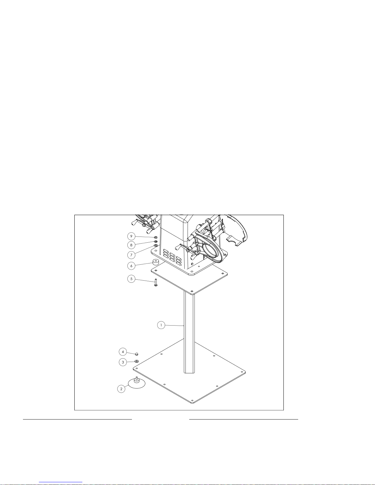
Installing the mixer on the Floor Stand.
1. Assemble (8) suction cups to the bottom of the floor stand using the hardware provided.
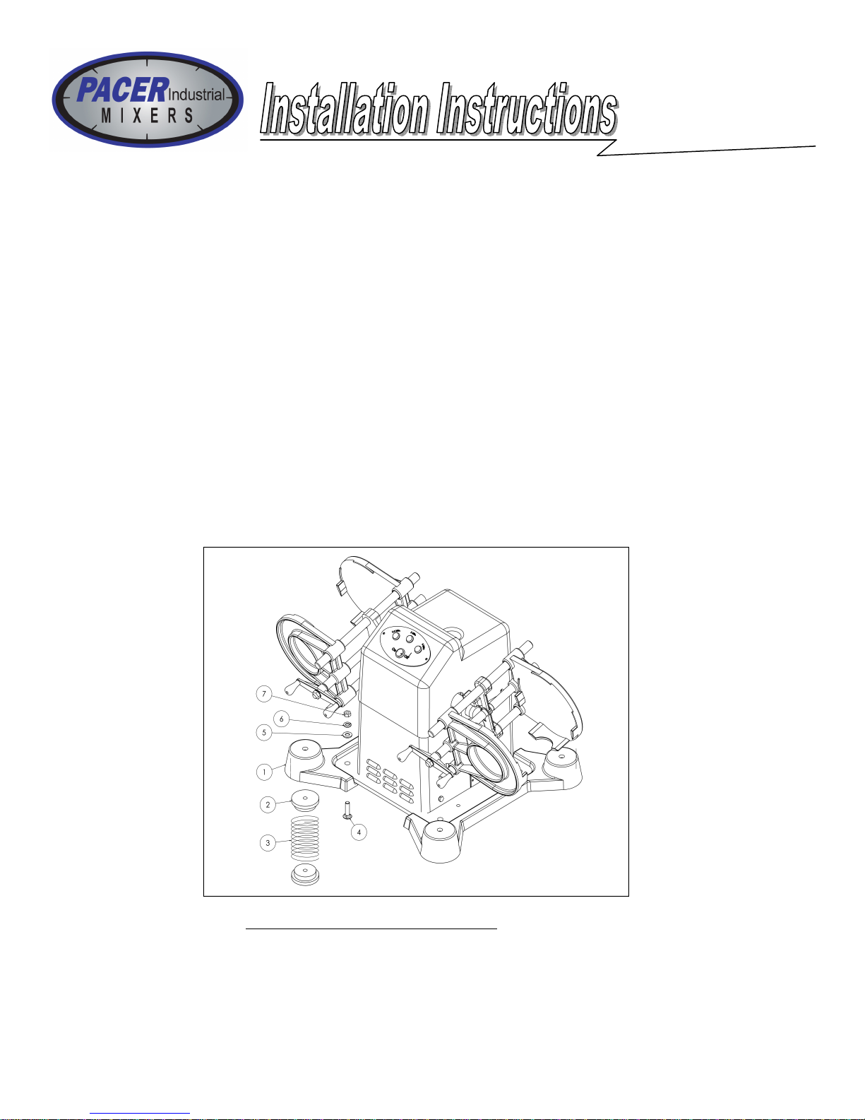
2. Assemble the mixer and (4) isolators (provided with the mixer) to the Floor Stand using the hardware pro-
vided.
3. Plug the power cord into a grounded receptacle (see page 7).
Note: Explosion proof models are not furnished with a power cord. The machine must be hard wired to
the power source by a qualified electrician.
4. If the suction cups do not grip the floor properly the base may creep while the mixer is operating. If this
does occur, anchor the base to the floor with rubber cement:
A. Tilt the mixer and floor stand until you can fit two 2” x 4” boards under the floor stand. This will lift
the suction cups far enough off the floor to apply rubber cement. Make sure the boards do not touch the
suction cups.
B. Clean the floor directly under the suction cups. Clean the contacting surface of the suction cups.
C. Apply rubber cement to the contacting surface of the suction cups and the floor directly under the suc-
tion cups.
D. Allow the rubber cement to dry until it becomes tacky. Remove the boards and lower the floor stand to
the floor.
E. Allow the rubber cement to dry overnight before running the mixer.
If you ever need to move the mixer, you can break the bond by inserting a wall scraper between the suction cup
and the floor.
Item Qty. Part Number / Description
1 1 PIM-10108 Floor stand
2 8 PIM-10069 Suction cup
3 8 PIM-10120 Flat washer, 5/16
4 8 PIM-10126 Acorn nut, 5/16-18
5 4 PIM-10115 Carriage bolt, 3/8-16 x 2.50
Item Qty. Part Number / Description
6 4 PIM-10049 Isolator
7 4 PIM-10119 Flat washer, 3/8
8 4 PIM-10172 Lock washer, split 3/8
9 4 PIM-10127 Nut, hex 3/8-16
6

Your mixer MUST BE PROPERLY GROUNDED. If there is an electrical short circuit, grounding reduces
the risk of electric shock.
The machine’s power cord has a grounded plug. This plug must be inserted into an electrical outlet that is
properly installed and grounded according to all local codes and ordinances.
If you must repair or replace the power cord or plug, do not connect the grounding wire to either flat-blade ter-
minal. The wire with insulation having an outer surface that is green (with or without yellow stripes) is the
grounding wire. Check with a qualified electrician if you don’t completely understand these grounding instruc-
tions, or if you are not sure whether the machine is properly grounded. DO NOT MODIFY the plug provided:
if it won’t fit the outlet, have a proper outlet installed by a qualified electrician.
Extension Cords
Avoid using extension cords. If an extension cord is unavoidable, consult a qualified electrician to determine
what type of extension cord will satisfy the grounding, current capacity, and other requirements of the particu-
lar situation.
RISK OF ELECTRIC SHOCK.
ALWAYS HAVE MACHINE PROPERLY
GROUNDED.
7

Safety Precautions
1. Before operating the machine, read this Owner’s manual carefully. For special air-driven model instruc-
tions see page 9.
2. Ground the machine properly. Be sure to follow proper electrical connection and grounding requirement
procedures.
3. Non-explosion proof models only: Do not use in hazardous environment where dust or flammable va-
pors are present. Do not mix flammable materials or materials with a low flashpoint per the material
safety data sheet.
4. Make sure can lids are tightly closed.
5. Do not mix breakable containers such as glass, porcelain, etc.
6. Ensure container is securely clamped.
7. All customers should be kept away from the work area.
8. The mixer should be operated by trained personnel only.
NOTE: The motor is protected by a thermal overload cutoff switch. If the temperature of the motor gets too
hot it will automatically shut off. The motor will not start again until it has cooled down.
Mixing Procedure
1. Turn the clamp handle counter-clockwise to open the clamp.
2. Place the container to be mixed in the clamp and turn the clamp handle clockwise until the container is se-
cured.
3. If mixing only one container on a dual mixer clamp an empty can (or a piece of 2” x 4” board) in the other
clamp.
4. After the containers are secured, set the timer for desired mix time.
5. The mixer will turn off after the mix time has elapsed.
Maintenance Procedures
Always disconnect machine from power source before maintaining or servicing.
Cleaning:
Keep the machine clean. Colorant or paint spilled on the machine can be cleaned with warm soapy water and/
or mineral spirits. After washing, oil the clamp rods and clamp lead screw to prevent rusting. Be careful not to
get the control panel or timer wet.
Lubrication:
Keep the clamp rods and clamp lead screw free of dirt, dried paint, and other materials. Remove any small
nicks with a fine file. Once a week apply a thin film of oil to the clamp rods and clamp screw.
8

The Instructions in this manual apply to both electrically powered and air driven models, with the exceptions
noted below.
Installation
Air Supply
Fill the Lubricator reservoir with an SAE-10W motor oil.
Connect a 10-cfm air supply to the inlet side of the ball valve and filter on the front of the mixer.
The regulator is factory set at 100psi.
The air supply must be at least 100psi to reliably operate the machine, and must not exceed 200psi.
Air driven models require no electrical connection.
Operation
Mixing Procedure
Air-driven models don’t have a timer. Control the mixing time by turning the air supply on and off.
Flammable materials may be mixed in air-driven models.
Maintenance
Cleaning
In addition to cleaning instructions on page 8, replace the air filter element when dirty. Replacement filter ele-
ments are available from you local Aro pneumatic supplies dealer.
Parts
PIM-10231 Air motor
PIM-10232 Filter / Lubricator
Air supply must not exceed 200psi.
9

PROBLEM CAUSE SOLUTION
Mixer won’t operate.
Clamp doesn’t hold can se-
curely.
Clamp binds when turning
clamp handle.
Mixer doesn’t shut off at
end of mixing cycle.
Mixer is unbalanced.
Power cord unplugged. Plug in power cord.
Motor thermal overload tripped. Allow motor to cool.
Building circuit breaker or fuse blown. Reset breaker of replace fuse.
Faulty timer. Have a qualified electrician replace
timer.
Broken, worn or loose drive belt. Visually inspect drive belt and replace
if necessary.
Worn or damaged clamp plate. Replace clamp plate.
Clamp lead screw and/or clamp rods
need to be lubricated. Apply a thin film of oil to clamp screw
and clamp rods.
Worn or damaged clamp plate. Replace clamp plate.
Faulty timer. Have a qualified electrician replace
timer.
Clamps are not positioned properly in
relation to the counterweight on pulley. With the clamps in a horizontal posi-
tion, counterweight on pulley should be
in the 9 o’clock position.
10

Pushbutton Timer
Dial Timer
11

Optional Safety Cover Switch,
Single Arm Mixer
Optional Safety Cover Switch,
Dual Arm Mixer
12
Explosion Proof Model

Bearing Housing Assembly
PIM-10175 SingleArm Mixer
PIM-10177 Dual Arm Mixer
Item Qty. Part Number / Description
1 1 PIM-10000 Bearing housing
2 1 PIM-10004 Camshaft
3 2 PIM-10014 Bearing cup
4 2 PIM-10013 Bearing cone
5 1 PIM-10002 Small spacer
6 1 PIM-10001 Large spacer
7 1 PIM-10158 Woodruff key #606
8 1 PIM-10006 Main shaft
10 1 PIM-10009 Spherical bearing
11 1 PIM-10005 Connector block
12 1 PIM-10003 Counterweight pulley
13 1 PIM-10110 Bearing housing cover
14 1 PIM-10011 Breather valve
Item Qty. Part Number / Description
15 2 PIM-10007 Side seal
16 1 PIM-10008 Front seal
17 1 PIM-10012 Gasket
18 1 PIM-10145 Hex head screw 3/8 - 24 x 2.00
19 1 PIM-10123 Internal tooth lockwasher 3/8
20 1 PIM-10128 Hex nut 3/8-24
21 4 PIM-10141 Hex head screw 1/4-20 x .75
22 1 PIM-10155 Set screw 1/4 - 20 x .50
23 1 PIM-10130 Nylock jam nut 5/8-16
24 1 PIM-10121 Flat washer .63 ID, 1.205 OD
25 1 PIM-10010 Cap plug
26 4 PIM-10122 Lockwasher, int / ext tooth 1/4
13

Item Qty. Part Number / Description
1 2 PIM-10016 Clamp rod holder
2 4 PIM-10017 Clamp rod
3 2 PIM-10019 Clamp lead screw
4 4 PIM-10021 Thrust bearing
5 2 PIM-10023 Crank handle
6 2 PIM-10234 Clamping block
7 1 PIM-10020 Clamp plate, left rear
8 1 PIM-10111 Clamp plate, left front
9 5 PIM-10018 Rollpin, 3/16 x 1.50
Clamp Assemblies
Item Qty. Part Number / Description
10 2 PIM-10157 #404 Woodruff key
11 1 PIM-10024 Clamp plate, right front
12 1 PIM-10025 Clamp plate, right rear
13 2 PIM-10124 Lockwasher, internal tooth 7/16
14 2 PIM-10129 Nut, hex jam 7/16-20
15 4 PIM-10172 Lockwasher, split 3/8
16 4 PIM-10128 Nut, hex 3/8-24
17 1 PIM-10173 Right clamp assembly (Dual arm
mixer only).
18 1 PIM-10174 Left clamp assembly (Single arm &
Dual arm mixers).
19 4 PIM-10022 Hex head tap bolt 3/8-24x2.50
14

Item Qty. Part Number / Description
1 1 PIM-10266 Motor, 115/230V 60/50Hz
2 1 PIM-10032 Motor pulley, 60Hz
PIM-10268 Motor pulley, 50Hz
3 1 PIM-10030 Motor fan
4 1 PIM-10031 Motor fan clip
5 4 PIM-10143 Screw, hex head cap 3/8-16 x 1.00
6 4 PIM-10172 Lockwasher, split 3/8
7 1 PIM-10033 Drive belt
8 4 PIM-10176 Screw, hex head cap 5/16-18 x 7/8
9 4 PIM-10125 Lockwasher, split 5/16
10 4 PIM-10120 Flat, washer 5/16 USS
11 4 PIM-10136 Nut, nylock jam 5/16-18
12 1 PIM-10177 Set screw, knurled cup point 5/16-18 x .50
13 1 PIM-10027 Frame weldment
Drive Assembly
15

Item Qty. Part Number / Description
1 1 PIM-10041 Bottom enclosure, front
2 1 PIM-10170 Bottom enclosure, back
3 4 PIM-10122 Lockwasher, int / ext tooth 1/4
4 4 PIM-10169 Screw, hex head cap 1/4-20 x 1.00
5 6 PIM-10140 Screw, flat head self tapping
#8 x .50
6 6 PIM-10171 Screw, pan head self tapping
#8 x .25
8 2 PIM-10154 Screw, pan head thread cutting
#8-18 x .50
9 2 PIM-10181 Screw, pan head self tapping
#4-24 X 5/16
Item Qty. Part Number / Description
10 1 PIM-10036 Timer knob
12 1 PIM-10045 Top enclosure
13 1 PIM-10035 Timer, 15 minutes
13 1 PIM-10163 Timer, 30 minutes
13 1 PIM-10164 Timer, 60 minutes
14 1 PIM-10037 Timer plate, 15 minutes
14 1 PIM-10165 Timer plate, 30 minutes
14 1 PIM-10166 Timer plate, 60 minutes
Enclosure Assembly & Mechanical Timers
16

Pushbutton TimerAssembly
Item Qty. Part Number / Description
1 1 PIM-10184 Controller
2 2 PIM-10154 Screw, pan head thread cutting #8-18 x .50
3 1 PIM-10134 Nut, nylock 1/4-20
4 3 PIM-10182 Pushbutton
5 1 PIM-10183 On / off switch
6 1 PIM-10168 PB timer plate
7 1 PIM-10118 Flat washer, 1/4 SAE
8 1 PIM-10185 Screw, flat head socket 1/4-20 x 1.50
17

Item Qty. Part Number / Description
1 1 PIM-10032 Motor pulley, 60Hz
2 1 PIM-10075 Explosion proof motor
3 1 PIM-10072 Bottom-front enclosure, x-proof
4 1 PIM-10076 Idler support
5 1 PIM-10109 Idler bearing
6 1 PIM-10077 Idler bushing
7 1 PIM-10117 Fender washer, 3/8 x 2.00 x .06
thick
8 4 PIM-10156 Tinnerman nut
9 1 PIM-10187 Cover plate, x-proof
10 2 PIM-10154 Screw, pan head thread cutting 8-18
x .50 type-25
11 4 PIM-10169 Screw, hex head cap 1/4-20 x 1.00
12 6 PIM-10122 Lockwasher, int-ext tooth 1/4
Item Qty. Part Number / Description
13 6 PIM-10171 Screw, pan head self tapping 8 x
5/16 type-AB
14 6 PIM-10140 Screw, flat head self tapping 8 x .50
type-AB
15 1 PIM-10120 Flat washer, 5/16 uss
16 1 PIM-10116 Carriage bolt, 5/16-18 x 1.75
17 1 PIM-10136 Nut, nylock jam 5/16-18
18 4 PIM-10144 Screw, hex head cap 5/16-18 x 1.00
19 4 PIM-10125 Lockwasher, split 5/16
20 1 PIM-10177 Set screw, knurled cup point 5/16-
18 x .50
21 1 PIM-10043 Bottom enclosure, back
22 1 PIM-10188 On/off lever, x-proof
23 4 PIM-10141 Screw, hex head cap 1/4-20 x .75
24 2 PIM-10134 Nut, nylock 1/4-20
Explosion-Proof Assembly
18
PIM-10189 Explosion proof V-belt (not shown)

Optional Safety Cover Assembly
Item Qty. Part Number / Description
1 1 Left safety cover, front and back (shown) or
Right safety cover, front and back
2 1 PIM-10056 Right hand female hinge
3 4 PIM-10225 Screw, flat head socket 10-32 x .75
4 1 PIM-10219 Left hand female hinge
5 6 PIM-10226 Flat washer, #10
Item Qty. Part Number / Description
1 2 PIM-10228 Screw, hex head 5/16-
18 x 1.25
2 4 PIM-10120 Flat washer, 5/16
4 2 PIM-10137 Nut, nylock 5/16-18
6 2 PIM-10147 Screw, Hex head 1/4-
20 x 1.50
7 2 PIM-10122 Lock washer, int / ext
tooth 1/4
8 1 PIM-10052 Left side brace weld-
ment
PIM-10061 Right side brace weld-
ment
9 2 PIM-10058 Bumper
10 2 PIM-10152 Screw, pan head 8-32 x .75
11 2 PIM-10133 Nut, nylock 8-32
12 4 PIM-10141 Screw, hex head 1/4-20
x .75 (for attaching rear cover)
13 4 PIM-10118 Flat washer, 1/4
14 4 PIM-10134 Nut, nylock 1/4-20
Item Qty. Part Number / Description
6 6 PIM-10132 Nut, nylock 10-32
7 1 PIM-10057 Latch
8 2 PIM-10218 Screw, pan head 10-32 x .75
9 1 PIM-10229 Pull handle
10 2 PIM-10152 Screw, pan head 8-32 x .75
11 2 PIM-10227 Flat washer, #8
19

Optional Safety Cover Switch Assembly (Left Side Shown)
Item Qty. Part Number / Description
1 2 PIM-10252 Screw, pan head 6-32 x 1.00
2 1 PIM-10247 Switch cover, safety
3 1 Rubber grommet
4 1 PIM-10251 Switch, safety cover
5 1 PIM-10246 Switch bracket, safety cover LS
1 PIM-10256 Switch bracket, safety cover RS
(not shown)
6 2 PIM-10253 Nut, nylock 6-32
Quantities listed are for Left Side. Double quantities of com-
mon parts for Dual Safety Covers.
Item Qty. Part Number / Description
7 1 PIM-10244 Switch actuator, safety cover LS
1 PIM-10255 Switch actuator, safety cover RS
(not shown)
8 4 PIM-10133 Nut, nylock 8-32
9 1 PIM-10245 Standoff, switch actuator
10 2 PIM-10152 Screw, pan head 8-32 x .75
11 1 PIM-10248 Support bracket, switch actuator
12 2 PIM-10254 Screw, pan head 8-32 x 1.00
13 2 PIM-10227 Flat washer, #8
Contact our Customer Service Department at:
Pacer Industrial Mixers
6270 Claude Way East
Inver Grove Heights, Minnesota 55076
Ph: 651-222-1900 or 888-236-1143
Fax: 651-222-8549
Last Revised: 11/30/16 20
This manual suits for next models
1
Table of contents