Pacific GSM DIN-3G User manual

DIN-3G
3G Network Communicator
Instructions: July 5, 2017, refers to the firmware version: 1.152N
Pacific GSM company expanded its range of DIN mounted
communicators for DIN-3G version of popular GSM DIN dialler
GSM-DIN3. The new DIN-3G available in 230V AC, 110V AC,
and also low 8-25V AC or DC version, so any electrical
application can be quickly and easily switched or monitored
through 3G network.
Through DIN-3G communicator can be remotely controlled
such as lighting, pumps, garage doors and gates.
May indicate a fault, loss of liquid in tanks, emergency conditions,
reboot servers or simply using a suitable sensor watch
objects, spaces and objects.
All easily through standard mobile phone
DIN-3G module is a fully pre-programmed, for most common
function (alarm report), just call the unit SIM number from phone
which you want to contact if a DIN-3G input 1 connected to GND,
DIN-3G will send you confirmation SMS with saved number and
that is all. Furthermore, the protocol allows you to edit text, switching commands, and settings of maximum
adaptation to your application. The options are twofold: either via USB-PC or SMS commands, please refer
manual below
Basic specification:
•DIN-3G communicator dimensions: 90 x 68 x 58 mm (H x W x D)
•UMTS 800/ 850/ 900/ 1900/ 2100 MHz
•GSM/EDGE 850/ 900/ 1800/ 1900 MHz
•Power supply voltage: 230V AC
•The communicator is backed up by internal Li-ion battery 3.7 V/550mAh
•Current consumption – communicator connected to network: approx. 20 mA, relays on 120mA, battery charging 320mA
•Max current consumption (GSM module transmits): peak of 1500mA max.
•Operating temperature: -20°C to +50°C
•2 logic inputs, active level GND.
Input is designed for connection of potential-free contacts!
•1 input for digital temperature sensor with a measuring, range from -20°C to 125°C.
(Temperature sensor sold separately with cable length 2m,3m and 5m)
•2 relay outputs 230V with load max 5A
•USB-PC configuration with USB cable (cable include in package)
•DIN-3G is designed in a dry environment. For outdoor installation, use the box with corresponding protection.
•6 authorized phone numbers can be set up
Basic Features:
•Two universal inputs with adjustable reaction to change, connection or disconnection of the loop.
•Inputs can be named (SMS text).
•Each input can send 2 different TXT for remote status equipments
•Inputs can be use for arming/disarming the communicator from remote device
•Inputs option for entry and exit time
•In case it is necessary to have an input permanently enabled (the watchdog state), can be switched into mode 24h. loop.
•Input for digital temperature sensor with automatic output control (thermostat).
•Information SMS in case of exceeding the set temperature or the temperature drops below the set limit.
•Device Status, you can always check the status via SMS.
•Easy configuration USB-PC software or SMS commands

LED indicator:
PWR/BAT
(Yellow, Green)
Yellow ON-main240V connected
Yellow OFF-main240V disconnected
Yellow flashing slowly-backup battery low voltage main 240V disconnected
Green flashing slowly - the communicator is arm *
Green OFF – communicator is disarmed *
Green flashing fast- entry or exit time indication
NETWORK (Blue)
Blue ON - Network is not ready / no signal
Blue flashing rapidly - a weak signal (<20%)
Blue flashing slowly - a good signal
RELAY1 (Yellow)
Yellow ON-output ON
Yellow OFF-output OFF
RELAY2 (Yellow)
Yellow ON-output ON
Yellow OFF-output OFF
* The communicator is arm means that the logic inputs mode ARM / DISARM is Armed
Normal operating status:
•Green LED flashes (ARM), blue LED flashes (device has Network signal).
Process or the inability to start up networking, respectively. another problem:
•The PWR/BAT and blue Network ON.
New Pre Pay SIM Card Activation
1) It is recommended to only use new standard SIM cards with no data stored. The DIN-3G has been tested with standard SIM
cards provided by Vodafone NZ, Spark NZ, 2Degrees NZ, Telstra AU, Optus AU, Vodafone AU, AT&T USA, T mobile USA
2) Place the new SIM card in an existing mobile phone.
3) Make a call to 777 Vodafone, *333 Spark or 200 2Degrees and follow the voice prompts to set up your PIN number to activate
the service and SIM, then it's ready to use.
4) We recommended register SIM online to manage SIM quick and easy any time. Registration process is quite quick. Click
on the Registerformy account tab from the www.vodafone.co.nz, www.spark.co.nz or www.2degreesmobile.co.nz website and
to follow the prompts and fill in the required details. Wait to receive a validation TXT to complete the registration.
5) Insert the SIM card into the Communicator.

New Zealand On Account SIM Card
Pacific GSM provide on account SMS plans for DIN-3G Communicator
1) 50 SMS’s to any network $9+GST per month
2) 150 SMS’s to any network $12+GST per month
Contact us for more information
DIN-3G Communicator Installation
The DIN-3G Communicator series is user friendly and easy to set up.
Mounting position determines the orientation of the front plate (side input power supply and relay outputs downwards).
Warning: Since this is a device powered from 230V mains voltage should always be installed with appropriate professional
with qualifications. Recommended wire cable for power supply: 2 x 1 mm2
DIN-3G Communicator Activation
DIN-3G is activated by inserting SIM card! If no SIM card is inserted, the device will not work and will
not operate and can’t be configure through PC.
Before the first start is recommended to fully charge the internal back up
battery with connection to mains voltage 230V, or USB cable to the PC.
Charging the internal battery is possible even without a SIM card.
1) Before connecting the power, connect the corresponding GSM antenna.
2) After connecting the power supply and SIM card,the module will go undergo a self-test cycle.
While in this cycle, the PWR/BAT and Network Led’s continuously on. After unit successfully
connects to the network the blue GSM LED will flash and PWR/BAT continuously on. Now
the unit is ready for programming.
3) Send TXT report command to the unit 1234 stat? If the command was correct, you will receive a TXT confirmation containing
GSM signal strength. If the network signal is not sufficient (below 40%), the move unit to better network signal area or use of
an external aerial.
Newer remove SIM card or aerial when power is connected!
Installation of PC configuration software for DIN-3G
• Download from the website www.pacificgsm.com configuration program DIN-3G configuration software under DIN-3G product page
downloads
• Run the installation program and follow the instructions of the setup program.
After Installation connect the DIN-3G via USB cable (included in package) to your computer.
The computer will download and install drivers for communication automatically
• After installation, the desktop icon is created DIN-3G on your PC, the default password for the program and the communicator is 1234

Basic configuration window
Advanced configuration window

Setting of basic parameters DIN-3G communicator
Description of configuration software for DIN-3G
• The device name is used for naming-communicator. This name will be displayed at the beginning of each SMS that send DIN-3G.
• Phone numbers - DIN-3G can communicate with up to six phone numbers with international code that you enter in this list
• Setting Phone Numbers – allocation for individual numbers setting
• Set input 1 and 2 - setting behaviour of inputs
• Set the relay 1 and 2 - setting behaviour of outputs
• System Time - synchronisation time with PC
• Password - used to change the password for the program, and SMS commands (default password is 1234). To save the password, it is
necessary to save the configuration, click Save to the device. Attention: The password must be four digits long and consist only digits.
• Bottom Status Bar - displays the network operator, the current status of the network signal and battery firmware version DIN-3G store
and process configuration.
Advanced settings DIN-G3 configuration software
• Starting value - setting the activation / deactivation, inputs and status outputs when communicator reset
• Entry and exit time- setting of timers
• Thermostat setting – setting of high and low limits include relay reaction
• ON/OFF commands- setting the SMS commands for arming and disarming inputs
• Service setting – setting of automatic status SMS and Information SMS temperature limits
• Power cut- if enabled, the service authorization numbers receive SMS in the event of a main power 230V failure
• Low battery - if enabled, the service authorization numbers receive SMS in case of low battery (25% or less)
• Temperature Sensor - if enabled, the service authorization numbers receive SMS in case of disconnection or failure the sensor
Table 1 – Phone Numbers:
Inputs 1 and 2
Set input 1 or input 2 to the alarm receiving phone number
Outputs 1 and 2
Set the number to control relay 1 or relay 2 via call. Beware, this function is not compatible with the function of
activation and deactivation calling option – see function below the A / D
Call
The alarm will be reported via call
SMS
The alarm will be reported via SMS
A/D
Control the activation and deactivation inputs vial call. Beware, this function is not compatible with the output
control call function.
Service
This number will be receiving service SMS reports*
* Service SMS by default: information on lost / restore 230V can also enable automatic sending of SMS status if exceeding temperature
set limits
Table 2 - Setting of input1 and input2:
Text SMS
Entre the text which will receive if alarm
Input reaction
Connecting- SMS alarm if input connected to GND, disconnecting – SMS alarm if input disconnected from GND,
Status Change – SMS alarm responding to connection and disconnection GND, ARM / DISARM – if input
connected to GND, the communicator is disarm when not connected to GND, is arm.
Input mode
ARM / DISARM - SMS alarm is triggered only if communicator arm. 24 hours - input always send SMS (e.g. for
the use of fire sensors, gas etc.).
Delay
Indicates how long must be GND connected or disconnected in input before SMS send out
Relay1 ON
When input activating SMS alarm input also switch output 1. The output reaction is subject to settings of output1
Block 15
The triggered input will be blocked to send SMS for next 15 minutes

Table 3 – Setting of output1 and output2:
Text SMS
Text, which will contain SMS confirming the output status change.
SMS ON
SMS command which will switch the output ON
SMS OFF
SMS command which will switch the output OFF
Call confirmation
Tel. number, which switch output will receive confirmation via call back only if output is switched ON
SMS
Tel. number, which switch output will receive confirmation via SMS if any change status on output
Timer
If the timer time set to a value other than 00:00:00, the output will be switched ON via call or SMS only for pre-
set time. After the countdown timer, the output is automatically switched off. Time format "hours: minutes:
seconds”. Maximum duration of the timer is 10 hours. Ex. 0:30:00 is set for 30 minutes.
Table 4 – Service Report Setting:
Automatic SMS
Will automatically send SMS at present time to phone numbers which enable service SMS.
Day
Day determines which day will be SMS send. Ex. Day = 1 means that the messages are sent each day.
Hour
Specifies the hour in which the SMS will be send out. Ex. 14 means that the SMS is sent within 14 hours (2pm)
Table 5 – Setting of entry/exit time:
Entry time
Delay timer before the SMS will be send out if the communicator not disarmed between this time. This function
not work on 24 Hours input setting
Exit time
The delay starts if the pre-set input (bellow) for Arm/Disarm activated table2 row 2 not work with SMS or call
control. This function not work on 24 Hours input setting
SMS OFF
SMS command which will switch the output OFF
Apply for input1
Allow entry a exit time for input1
Apply for input2
Allow entry a exit time for input2
Table 6 – Thermostat setting:
High limit
Set the temperature which will switch output OFF in heating mode and will switch output ON in cooling mode
Low limit
Set the temperature which will switch output ON in heating mode and will switch output OFF in cooling mode
Thermostat switch
relay1
Assign relay output
Thermostat switch
relay2
Assign relay output
Mode
Sets the thermostat in to heating or cooling mode
* The temperature can be controlled in the range of -20 to +99.9 ° C.
Table 7 – Setting the SMS temperature limits:
Temperature info
SMS
Will allows send SMS if the temperature reach the set limit
High limit
Set the temperature which will triggered SMS out if the reach set limit or higher
Low limit
Set the temperature which will triggered SMS out if the reach set limit or lower
Hysteresis
This setting determines the temperature at which the communicator will sends SMS Information about
exceeding upper or lower limits again the temperature is the upper limit for the difference: the upper limit -
hysteresis for the lower limit of the sum of: lower limit + hysteresis.
Example: the upper limit is set at 35 °, the lower limit to 20 °, hysteresis at 5 °. When exceeding
35 °communicator will send SMS report about exceeding the upper limit, then if the temperature drops below
30 ° C and then rises above 35 ° C, it is again sent out the SMS report about exceeded the upper limit.
If the temperature drops below 20 ° C, communicator will send SMS report about exceeding the lower limit, then
if the temperature increase up 25 ° C and then drop below 20 ° C, it is again sent out the SMS report about
exceeded the lower limit.
* The temperature can be controlled in the range of -20 to +99.9 ° C.

SMS Commands
Principles for using SMS commands:
•Each SMS command must include at the beginning the password. E.g. to determine the status send SMS: "1234 stat?"
•SMS commands are not case sensitive. E.g. command to determine the status, you can send STAT? / stat? / STat?
•If possible, always use the DIN-3G PC configuration software, it’s easy and intuitive
Reset a forgotten password:
If you forget the password for SMS, you can reset default password (the default password is 1234) as follows:
- Send SMS to the number of the SIM card in DIN-3G, which contains only IMEI number.
- No password or command only IMEI number.
- Wait until the DIN-3G blue LED will flash quickly (SMS was received)
- Remove SIM card within 20 seconds.
- DIN-3G password is now restored to 1234
- If the SIM card not disconnected within 20 seconds after DIN-3G receive an SMS with the IMEI number, password will not be restored.
Table 8 - SMS commands:
STAT?
Determines the current status of the communicator (network operator, signal strength, temperature if
the temperature sensor is connected and number of alarms since the last activation)
TEMP?
Determines the current temperature
HIST?
List of alarm history from last activation
NPIN
Changes the password for the SMS commands. Example. "NPIN 1111" changes the original password
to1111.
SET DEFAULT VALUES
Restores the default settings of communicator. The phone numbers are not deleted.
CLEAR ALL NUMBERS
Clears all programmed phone numbers.
NUMBER1
Stores the phone number to the list. Example.: NUMBER1 +642123456
NUMBER1 DELETE
Clears the number 1 from the list.
SNUMBER1 ABCDEFGH
Change setting for number1 see table 9
SETSYS ABCDEFG
Change of system setting see table 10
SETIN1 ABCDEF
Change of digital input setting see table 11.
SETR1 ABCDEFGH
Change of output setting see table 12.
SETTHERM ABCDEFGHIJK
Change of thermostat setting see table 13.
SETTEMP ABCDEFGHIJ
Setting of monitoring temperature SMS limits see table 14.
Table 9 - Setting of telephone numbers:
Command:
SNUMBER1 to SNUMBER6, send SMS: SNUMBERX ABCDEFGH
Parameter A
A=1 – input1 report alarms to phone number, A=0 – input1 alarms does not reported to phone number
Parameter B
B=1 – input2 report alarms to phone number, A=0 – input2 alarms does not reported to phone number
Parameter C
C=1 – phone number control output1 by dialling, B=0 - phone number not control output1 by dialling. *
Parameter D
D=1 – phone number control output2 by dialling, B=0 - phone number not control output2 by dialling. *
Parameter E
E=1 – alarm is reported to phone number via call, C=0 – alarm not reported via call.
Parameter F
F=1 – alarm is reported to phone number via SMS, D=0 – alarm not reported via SMS.
Parameter G
E=1 – phone number control activation and deactivation by dialling, E=0 - phone number not control activation
and deactivation by dialling. *
Parameter H
F=1 – phone number receive service SMS, F=0 – phone number not receive service SMS.
Example:
SNUMBER1:10000101 means that the number one receives alarm information from input 1,
dial control output is off, the alarm reported via SMS, dial control ARM/DISARM is off, service SMS activated
* The call control can operate output s or the activation / deactivation of the communicator.
These functions cannot be the used on the one phone numbers at the same time.
Table 10 - Automatic SMS status setting and the status after reset:
Command:
SETSYS, send SMS: SETSYS ABCDEFG
Parameter A
A=1-Sending automatic status SMS enabled, A = 0 - automatic status SMS sending is disable.
Parameter B
Specifies which day SMS sent. You can enter 1 to 9
Parameter C
Tens of hours. You can enter 0-2. *
Parameter D
Units of hours. You can enter 0-9. *

Parameter E
E = 0 - communicator is arm after the restart, E = 1 - communicator is disarm after restart, E = 2 –
communicator status is same like last status before restart.
Parameter F
F = 0 - output 1 is switched on after the restart, F = 1 - output 1 is switched off after restart, F = 2 - Output 1
status is same like last status before restart.
Parameter G
G = 0 - output 2 is switched on after the restart, F = 1 - output 2 is switched off after restart, F = 2 - Output 2
status is same like last status before restart.
Example:
SETSYS: 1111222 means automatic SMS enabled which is sent each day at 11:00 hours. After
restart the communicator last status will be restored.
* Clock can be set from 0 to 23.
Table 11 - Digital input setting:
Command:
SETIN1 or SETIN2, send SMS: SETINX ABCDEF
Parameter A
A = 0 - input reacts to a connection to GND, A = 1 - input reacts to a disconnect GND, A = 2 – input reacts to the
any change
Parameter B
B = 0 – input is subject to activation / deactivation communicator1234
1234
, B = 1 - input is a 24-hour loop (permanent
watch).
Parameter C
Input delay – unit seconds. You can enter 0-9. *
Parameter D
Input delay - tenth seconds. You can enter 0-9. *
Parameter E
E = 1 - when the input is activated the output will switch , E = 0 - input activation does not switching output
Parameter F
F = 1 - after the input is activated the reporting will be blocked for 15 min, F = 0 – the reporting does not block
Example:
SETIN1 210201 means that input react to any change, input is under continuous monitoring (24h
loop), delay input is 0.2 seconds, when input activated does not switch output and after an alarm input is
blocked for 15 minutes.
* Input delay (transient treatment) can be adjusted from 0.2 to 9.9 seconds
Table 12 - Output settings:
Command:
SETR1 or SETR2 send SMS: SETR1 ABCDEFGH
Parameter A
A = 1 – after the output switched on or off via dialling or SMS the unit will confirm switching via call back to the
same number, A = 0 – unit does not confirm switching via call.
Parameter B
B=1 - after the output switched on or off via dialling or SMS the unit will confirm switching via SMS to the same
number, A = 0 – unit does not confirm switching via SMS.
Parameter C
Timer output - tens of hours. You can enter 0-1. *
Parameter D
Timer output - unit of hours. You can enter 0-9. *
Parameter E
Timer output - tens of minutes. You can enter 0-5. *
Parameter F
Timer output - unit of minutes. You can enter 0-9. *
Parameter G
Timer output - tens of seconds. You can enter 0-5. *
Parameter H
Timer output - unit of seconds. You can enter 0-9. *
Example:
SETR1: 01000000 means that a change in the output is only confirmed by SMS, timer output is
set to 00hour, 00minutes and 00 seconds.
* The timer output can be set from 0 to 10 hours. If you do not use a timer, enter value to 0
Table 13 - Setting the thermostat:
Command:
SETTHERM, send SMS: SETTHERM ABCDEFGHIJK
Parameter A
A = 1 - thermostat controls output 1, A = 0 - thermostat does not control output 1
Parameter B
B = 1 - thermostat controls output 2, A = 0 - thermostat does not control output 2
Parameter C
Upper thermostat limit - mark. You can set the + or -
Parameter D
Upper thermostat limit - tens ° C. You can set 0-9. *
Parameter E
Upper thermostat limit - units ° C. You can set 0-9. *
Parameter F
Upper thermostat limit - tenths ° C. You can set 0-9. *
Parameter G
Lower thermostat limit - mark. You can set the + or -
Parameter H
Lower thermostat limit - tens ° C. You can set 0-9. *
Parameter I
Lower thermostat limit - units ° C. You can set 0-9. *

Parameter J
Lower thermostat limit - tenths ° C. You can set 0-9. *
Parameter K
K = 0 - thermostat is in the heating mode, K = 1 - thermostat is in cooling mode
Example:
SETTHERM: 01+320+2500 means that the thermostat does not controls output 1but output2 the upper limit is
set to +32.0 ° C, lower at +25.0 ° C and the thermostat is in heating mode. In other words: the thermostat stops
heating to 32.0 ° C and starts heating at 25.0 ° C.
* The temperature can be controlled in the range of -20 to +99.9 ° C.
Table 14 - Setting the SMS temperature limits:
Command:
SETTEMP, send SMS: SETTEMP ABCDEFGHIJ
Parameter A
A = 1 - Exceeding temperature SMS information limits is ON
A = 0 - Exceeding temperature SMS information limits is OFF
Parameter B
Upper limit of temperature monitoring - mark. You can set the + or -
Parameter C
Upper limit of temperature monitoring - tens ° C. You can set 0-9. *
Parameter D
Upper limit of temperature monitoring - units ° C. You can set 0-9. *
Parameter E
Upper limit of temperature monitoring - tenths ° C. You can set 0-9. *
Parameter F
Lower limit of temperature monitoring - mark. You can set the + or -
Parameter G
Lower limit of temperature monitoring - tens ° C. You can set 0-9. *
Parameter H
Lower limit of temperature monitoring - units ° C. You can set 0-9. *
Parameter I
Lower limit of temperature monitoring - tenths ° C. You can set 0-9. *
Parameter J
Hysteresis temperature setting ° C. You can set 1 to 9
Example:
SETTEMP: 0+300+1801 means that the exceeding temperature SMS information limits is OFF upper limit is
30.0, lower limit is 18.0 and hysteresis is 1 degrees, sending SMS
exceeding the upper limit is possible if the temperature drops below 29 ° C and lower limits when it goes above
19 ° C (set hysteresis).
* The temperature can be monitored in the range of -20 to +99.9 ° C.
Guidelines for Safe and efficient use:
Please read this information before using your DIN-3G Communicator. These instructions are intended for your safety. Please follow
these guidelines. If the product has been subject to any of the conditions listed below or you have any doubt as to its proper function,
make sure you have the product checked by a certified service partner before using it. Failure to do so might entail a risk of product
malfunction or even a potential hazard to your health.
Recommendations for Safe use of product:
•Always treat your product with care and keep it in a clean and dust-free place.
•Do not expose your product to liquid or moisture or humidity.
•Do not expose your product to extreme high or low temperatures.
•Do not drop, throw or try to bend your product.
•Do not attempt to disassemble or modify your product. Only authorised personnel should perform service.
•Do not use your product in an area where a potentially explosive atmosphere exists.
Antenna:
The DIN-3G Communicator has an antenna. Use of antenna devices not marketed by Pacific GSM Limited specifically for this model
could damage your DIN-3G Communicator, reduce performance, and produce SAR levels above the established limits (see below).
Radio Frequency (RF) Exposure and Specific Absorption Rate (SAR):
The DIN-3G Communicator is a low-power radio transmitter and receiver. When it is turned on, it emits low levels of radio frequency
energy (also known as radio waves or radio frequency fields).
Governments around the world have adopted comprehensive international safety guidelines, developed by scientific organizations,
through periodic and thorough evaluation of scientific studies. These guidelines establish permitted levels of radio wave exposure for the
general population. The levels include a safety margin designed to assure the safety of all persons, regardless of age and health, and to
account for any variations in measurements. Specific Absorption Rate (SAR) is the unit of measurement for the amount of radio fre-
quency energy absorbed by the body. The SAR value is determined at the highest certified power level in laboratory conditions, but the
actual SAR level of the DIN-3G Communicator while it is operating can be well below this value. This is because the DIN-3G Communi-
cator is designed to use the minimum power required to reach the network. Variations in SAR below the radio frequency exposure
guidelines do not mean that there are variations in safety. While there may be differences in SAR levels among GSM Communicators,
all Pacific GSM communicator models are designed to meet radio frequency exposure guidelines

Disposal of old Electrical and Electronic Equipment:
This symbol indicates that all electrical and electronic equipment included shall not be treated as household waste. Instead it
shall be left at the appropriate collection point for recycling of electrical and electronic equipment. By ensuring this product is
disposed of correctly, you will help prevent potential negative consequences for the environment and human health, which
could otherwise be caused by inappropriate waste handling of this product. The recycling of materials will help to conserve
natural resources. For more detailed information about recycling this product, please contact your local city office, your
household waste disposal service or the shop where you purchased the product.
End User Licence Agreement:
This wireless device, including without limitation any media delivered with the device, (“Device”) contains software owned by Pacific
GSM Limited and its third-party suppliers and licensors (“Software”). As user of this Device, Pacific GSM Limited grants you a non-
exclusive, non-transferable, non-assignable license to use the Software solely in conjunction with the Device on which it is installed
and/or delivered with. Nothing herein shall be construed as a sale of the Software to a user of this Device. You shall not reproduce,
modify, distribute, reverse engineer, decompile, otherwise alter or use any other means to discover the source code of the Software or
any component of the Software. For avoidance of doubt, you are at all times entitled to transfer all rights and obligations to the Software
to a third party, solely together with the Device with which you received the Software, provided always that such third party agrees in
writing to be bound by these rules. You are granted this license for a term of the useful life of this Device. You can terminate this license
by transferring all your rights to the Device on which you have received the Software to a third party in writing. If you fail to comply with
any of the terms and conditions set out in this license, it will terminate with immediate effect.
Disclaimer:
This device is designed for indoor use only unless protected in appropriate enclosure. The 3G Communicator is reliant on adequate
3G/2G coverage. In the event of inadequate or no 3G or 2G coverage, Pacific GSM Limited cannot be held liable for any damages.
The GSM Communicator was tested with SIM cards provided by “Vodafone NZ, Spark NZ, 2Degrees NZ, Telstra AU, Optus AU, Voda-
fone AU, AT&T USA, T mobile USA”. Pacific GSM Limited cannot be held liable for any malfunction with the use of other SIM cards.
Only use auxiliary equipment tested and approved by Pacific GSM Limited. Do not attempt to take apart, open, service, or modify the
hardware device. Doing so could present the risk of electric shock or another hazard. Any evidence of any attempt to open and/or mod-
ify the device, including peeling punching, or removal of any labels, will void the Limited Warranty. Never pass security code or the
mobile number of the 3G Communicator to an unauthorised third party. All rights reserved. Except as expressly provided herein, no part
of this manual may be reproduced, copied, transmitted, disseminated, downloaded or stored in any storage medium, for any purpose
without the express prior written consent of Pacific GSM Limited. Information in this document is subject to change without any notice.
Pacific GSM Limited reserves the right to change or improve its products and to make changes in the content without obligation to notify
any person or organisation of such changes or improvements. Visit the Pacific GSM Web site (www.pacificgsm.com) for current updates
and supplemental information concerning the use and operation of this and other Pacific GSM products.
Warranty:
Subject to the condition of this Limited Warranty, Pacific GSM Limited warrants this product to be free from defects in design, material
and workmanship at the time of its original purchase by a customer. This Limited Warranty will last for a period of two year as from the
original day of purchase and for a period of one year for all original accessories (aerial). The warranty does not cover any damages
caused due incorrect installation and the use of any auxiliary devices not approved by Pacific GSM Limited.
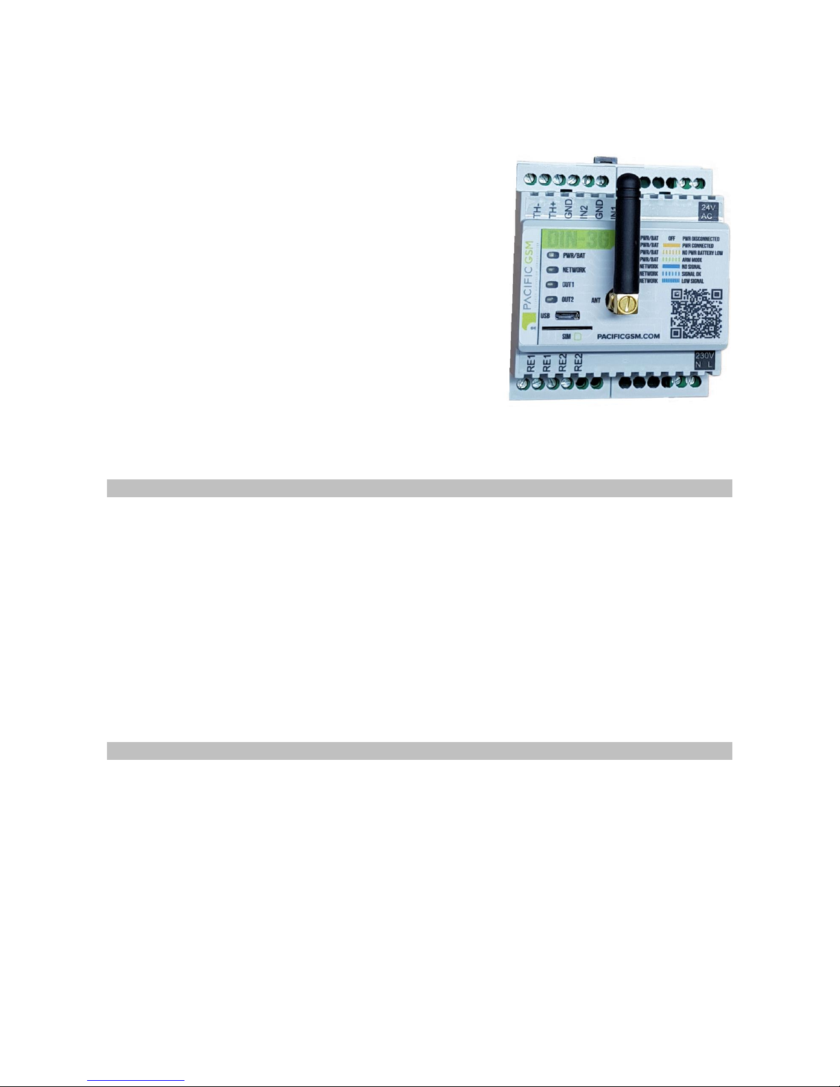
DIN-3G complies with requirements of the following regulations:
•EN 55032:2015
•EN 61000-6-2:2005
•EN 61000-4-2:2009 –criterion A
•EN 61000-4-3:2006 –criterion A
•EN 61000-4-4:2012 –criterion B
•EN 61000-4-5:2014 –criterion A
•EN 61000-4-6:2014 –criterion A
•EN 61000-4-11:2004 –criterion A
•EN 60950-1:2006
Australia / New Zealand Responsible Supplier number E4647 R-NZ
Technical Support:
Pacific GSM Limited
Contact No: +64 9 948 476 2 +64 21-476747
E-mail: info@pacificgsm.co.nz
Web: www.pacificgsm.com
© Published: 1 November 2017 by Pacific GSM Limited
No part of this booklet may be reproduced without written permission
Table of contents
Other Pacific GSM Cell Phone manuals