Pacific GSM DIN-4G User manual

DIN-4G
3G/4G Network Communicator
Instructions: April 17, 2022, refers to the firmware version: 1.1.0 and software version 1.0.1
DIN-4G controller is a new version of Pacific GSM communicator The
new version of Pacific GSM DIN communicator is based on 3G/4G
module with four inputs, four outputs and two temperature inputs to
suits most basic applications such as monitoring process, status of
large variety of equipment’s in multiple industries or switching
remotely any device via custom text message or drop call.
Application can be quickly and easily switched or monitored
anywhere around the world via 4G/3G network thanks to our global
4G/3G module. Through DIN-4G communicator can be remotely
controlled such as lighting, pumps, garage doors and gates. May
indicate a fault, loss of liquid in tanks, emergency conditions, reboot
servers or simply using as a main power supply monitoring. DIN-4G
can be used as an alarm system with suitable sensors to protect
objects and spaces.
All easily through standard mobile phone
Basic specification:
•DIN-4G module dimensions: 91 x 72 x 58 mm (H x W x D)
•UMTS (3G) B1/B5/B8 (2100/850/900 MHz)
•LTE (4G) B1/B3/B5/B8/B28 (2100/1800/850/900/700 MHz)
•Power supply voltage: 100- 250V AC with battery back up
•Back up by internal Li-ion battery 3.7 V/550mAh
•Current consumption – 4G module connected to network, standby: approx. 5mA
•Max current consumption (4G module transmits): peak of 40mA max.
•Operating temperature: -20°C to +50°C
•4x logic input, activated connection/disconnection to GND
•2x digital temperature input with a measuring range from -55°C to 125°C
•2x relay NO/NC max load 5A 250V AC
•2x transistor output open collector
•USB-PC configuration with USB cable
•10 authorized phone numbers can be set up
•DIN-4G mounting for DIN rail
•DIN-4G is designed in a dry environment. For outdoor installation, use the box with corresponding protection.
Basic Features:
•Four universal inputs with adjustable reaction to change, connection or disconnection of the loop.
•Inputs can be named (SMS text).
•Each input can send 2 different TXT for remote status equipments
•Inputs can be use for arming/disarming the communicator from remote device
•Inputs regime arm/disarm or 24h. lop
•Inputs for digital temperature sensor with automatic output control (thermostat).
•Information SMS in case of exceeding the set temperature or the temperature drops below the set limit.
•Power supply monitoring SMS notification if supply voltage reaches the set limits
•4 outputs with multiple configuration options. Activation via TXT or call with timer option, siren, arm mode indication etc.
•Device Status, you can always check the status via SMS.

LED indicator:
NETWORK (Blue)
ON-SIM inserted no network or unit start up
OFF- SIM removed
Flashing slowly – network signal ok
Flashing fast- network signal low
STATUS (Green)
OFF-disarm
Flashing slowly - arm
Power (Green)
ON-Main power connected
Flashing slowly – Main power disconnected, operated from battery
Relay1 (Orange)
ON-Relay ON
OFF-Relay OFF
Relay2 (Orange)
ON-Relay ON
OFF-Relay OFF
* The communicator is arm means that the logic inputs mode ARM / DISARM is Armed
Normal operating status:
•Blue Network LED flashes slowly network connected
•Green Power LED ON power connected
Process or the inability to start up networking, respectively. another problem:
•The network and power LED’s ON.
New Pre Pay SIM Card Activation
1) It is recommended to only use new standard SIM cards with no data stored. DIN-4G has been tested with standard SIM cards
provided by Vodafone NZ, Spark NZ, 2Degrees NZ, Telstra AU, Optus AU, Vodafone AU, AT&T USA, T mobile USA
2) Place the new SIM card in an existing mobile phone.
3) Make a call to 777 Vodafone, *333 Spark or 200 2Degrees and follow the voice prompts to set up your PIN number to activate
the service and SIM, then it's ready to use.
4) We recommended register SIM online to manage SIM quick and easy any time. Registration process is quite quick. Click
on the Registerfor my account tab from the www.vodafone.co.nz, www.spark.co.nz or www.2degreesmobile.co.nz website and
to follow the prompts and fill in the required details. Wait to receive a validation TXT to complete the registration.
5) Insert the SIM card into the Communicator.

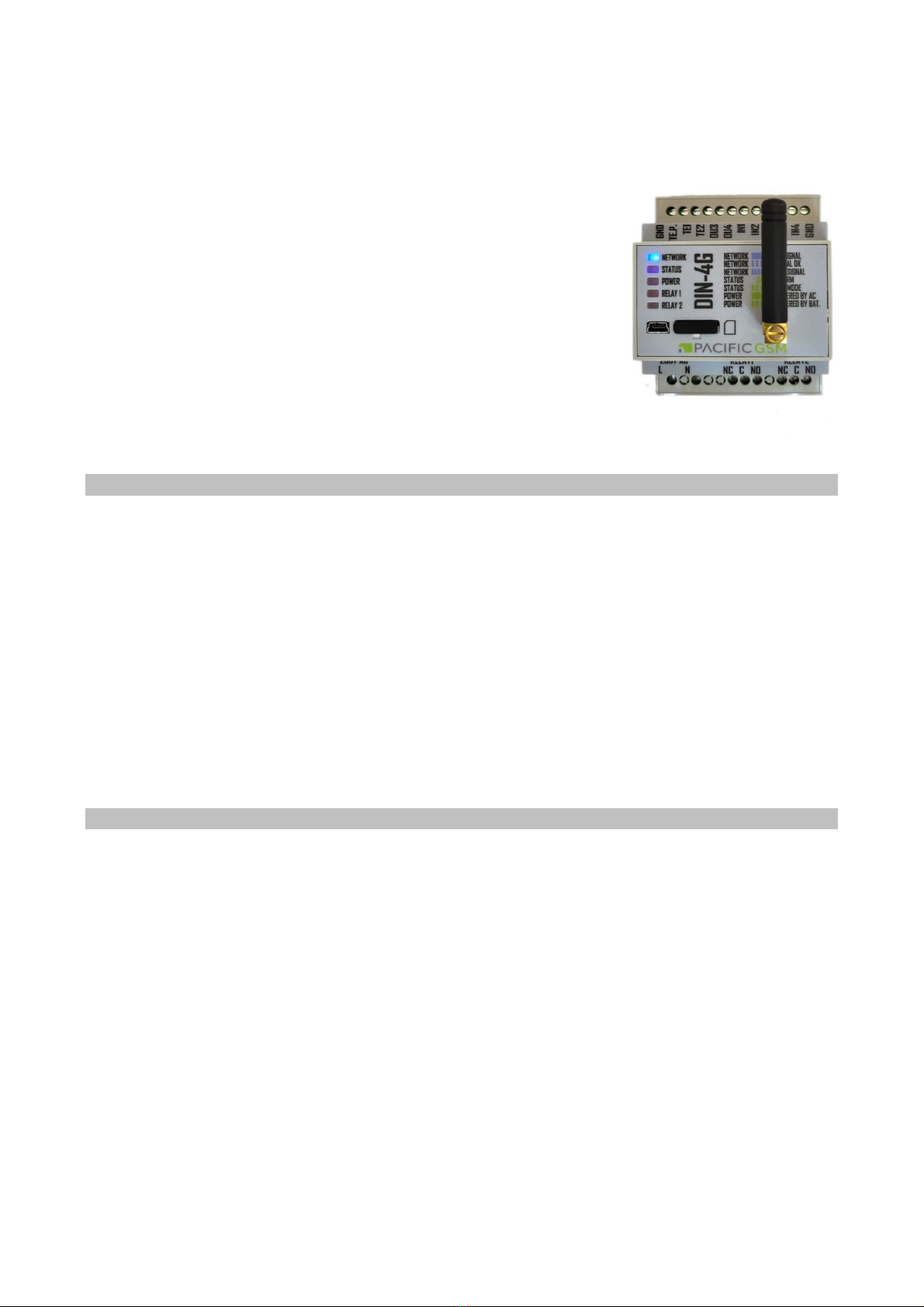
DIN-4G Communicator Installation
The DIN-4G Communicator series is user friendly and easy to set up.
Warning: Since this is a device powered from 230V mains voltage should always be installed with appropriate professional
with qualifications. Recommended wire cable for power supply: 2 x 1 mm2. The DIN-4G is designed for indoor use only, for
outdoor installation use enclosure with corresponding IP rating.
DIN-4G Communicator Activation
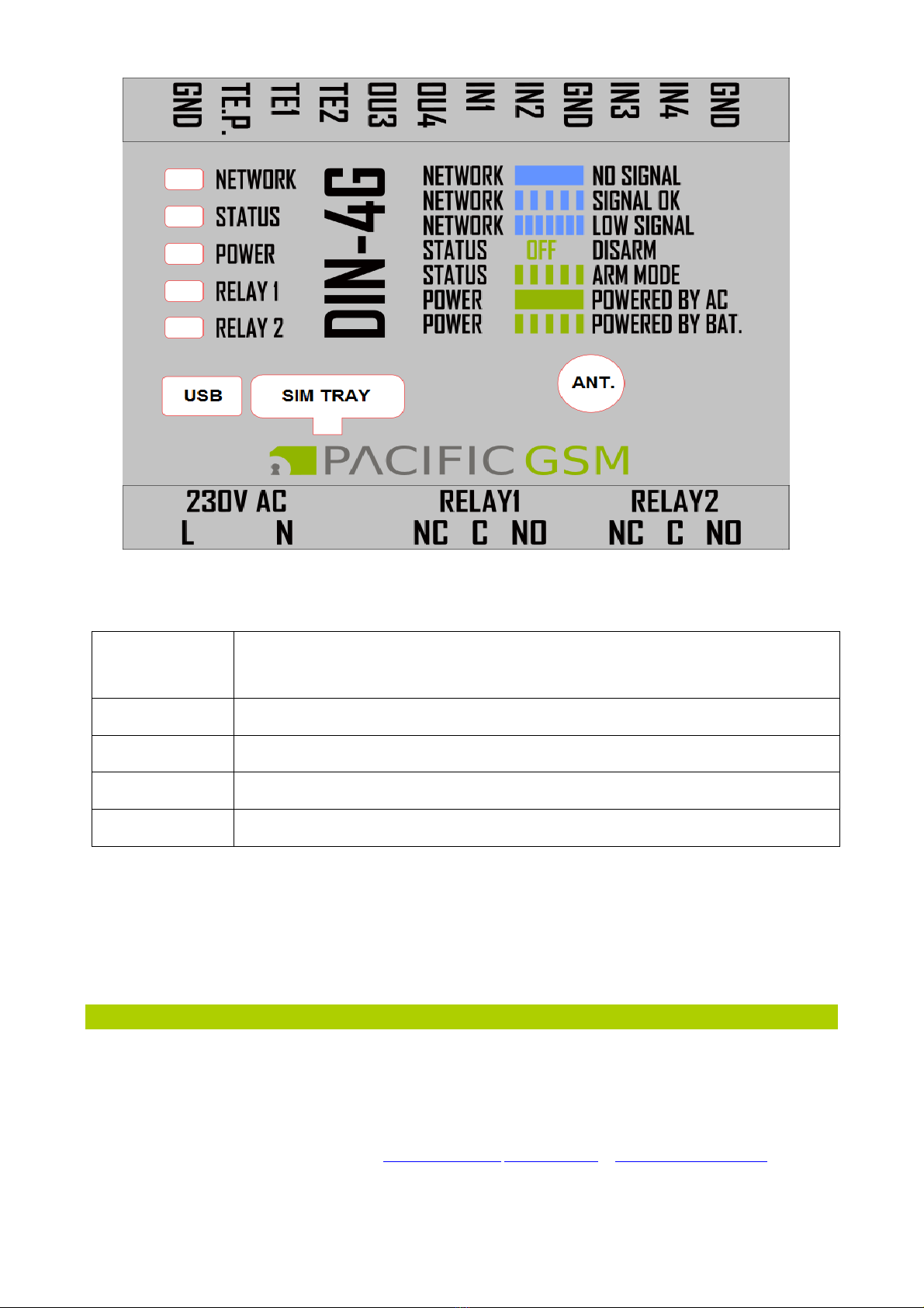
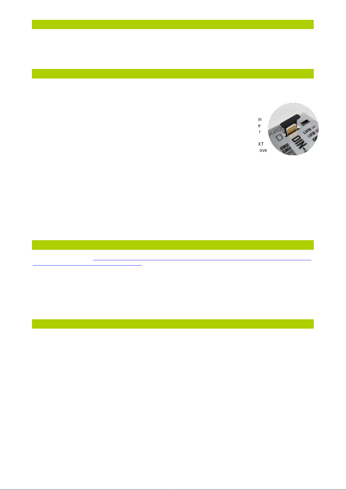
DIN-4G is activated by inserting SIM card! Place the nano SIM card in to tray and then slide inside the
DIN-4G as per picture. If no SIM card is inserted, the device will not work and will not operate and
can’t be configure through PC.
1) Before inserting the SIM, connect the corresponding GSM antenna.
2) After connecting the power supply and SIM card, the module will go undergo a self-test cycle. While in
this cycle, the PWR/BAT and Network Led’s continuously on. After unit successfully connects to the
network the blue network LED will flash and PWR/BAT continuously on. Now the unit is ready for
programming.
3) Send TXT report command to the unit 1234 stat? If the command was correct, you will receive a TXT
confirmation containing GSM signal strength. If the network signal is not sufficient (below 20%), move
the unit to better network signal area or use of an external aerial.
Never remove SIM card or aerial when power is connected!
The Communicator DIN-4G series is a fully pre-programmed from manufactory, just call the DIN-4G SIM phone num-
ber from phone which you want to receive in future report, the DIN-4G will automatically save called number under
position 1 (NUMBER1).
From this moment if the input 1 to 4 connected to GND for the DIN-4G module will send the pre-programmed SMS (DIN-4G: input 1-4
Activated) to this number, you can easily add additional phone numbers (up to 10) via simple PC configuration software or SMS com-
mand. Output can be operated via default commands 1234 ON1 ON or 1234 OFF1 etc.
Never remove aerial when power is connected!
Installation of PC configuration software for DIN-4G
• Download from the website https://www.pacificgsm.com/GSM-3G-4G-IoT-control/GSM-3G-4G-communicators/4G-IoT-controller-230V-
LTE-communicator-relay-switch-with-battery-back-up configuration program DIN-4G configuration software under DIN-4G product page
downloads
• Run the installation program and follow the instructions of the setup program.
After Installation connect the DIN-4G via USB cable (included in package) to your computer.
The computer will download and install drivers for communication automatically
• After installation, the desktop icon is created DIN-4G on your PC, the default password for the program and the communicator is 1234
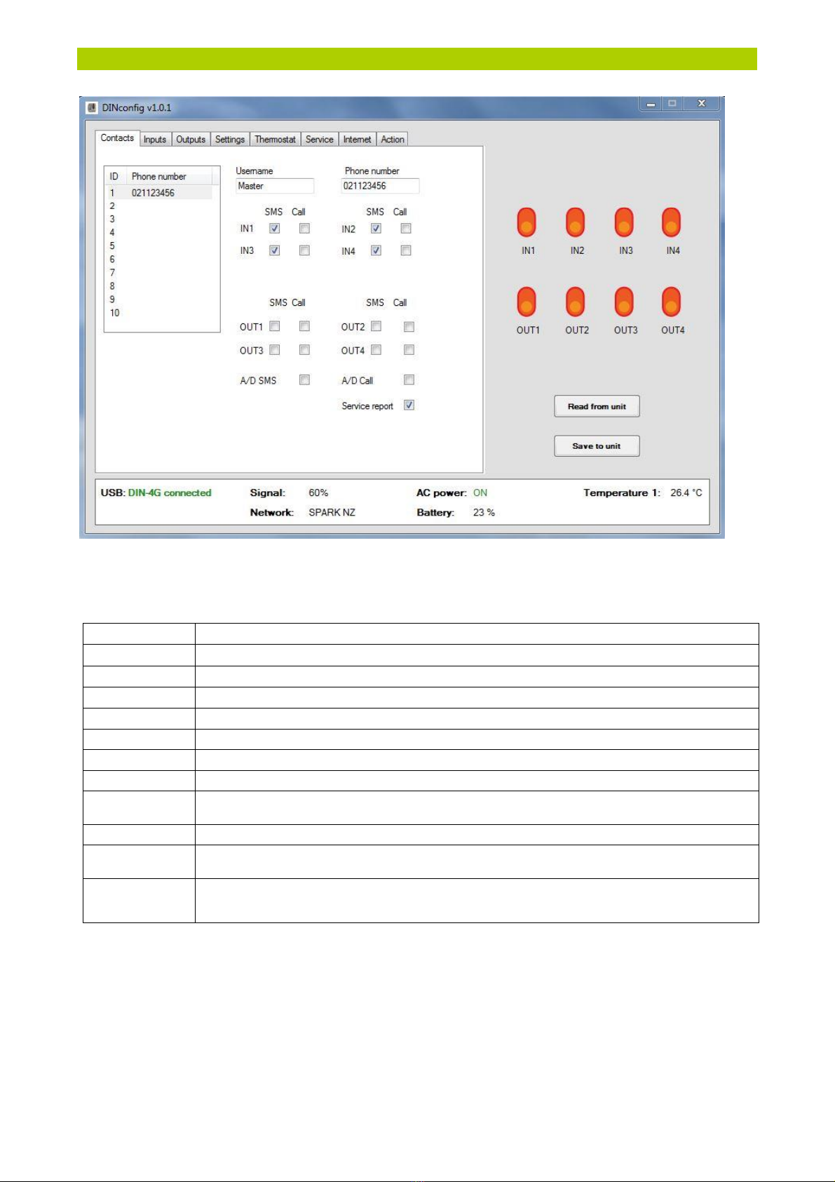
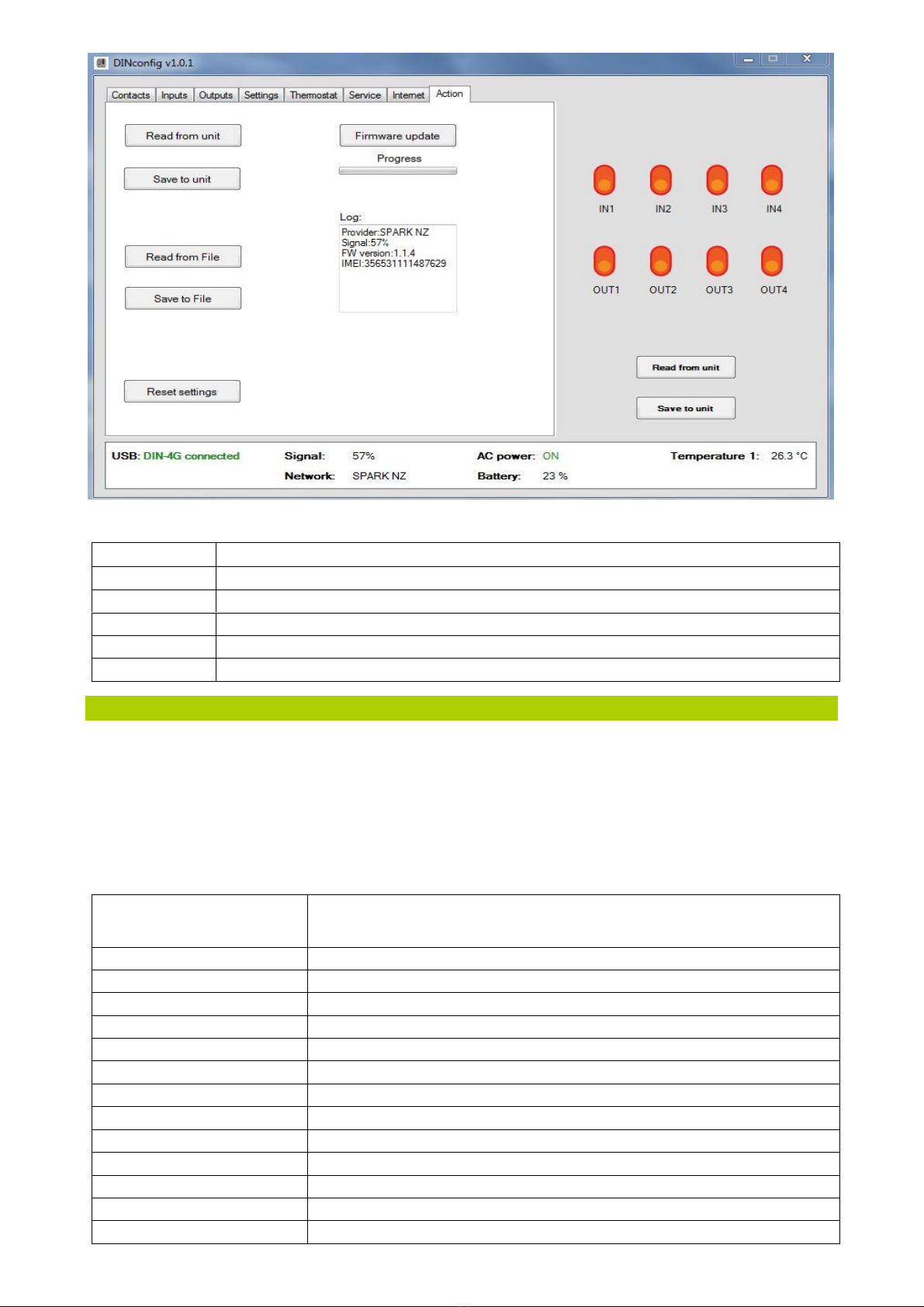
Description of configuration software for DIN-4G
The configuration software has eight tabs:
Contacts In this tab up to 10 users can be set with username, telephone numbers with reports and authorisation control
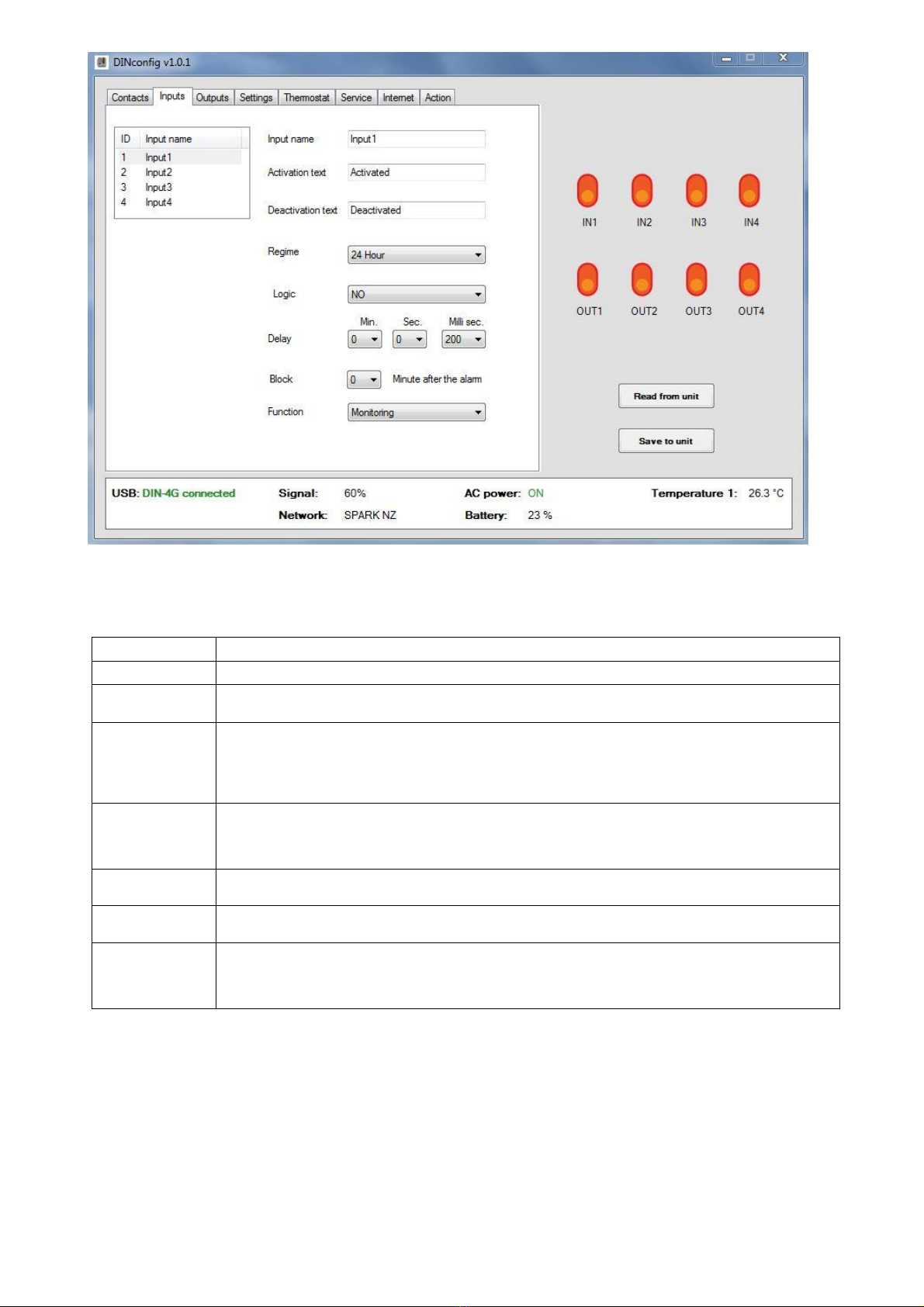
Inputs In this tab can be set all parameters for inputs include name, reporting’s texts, logics, delay, function etc.
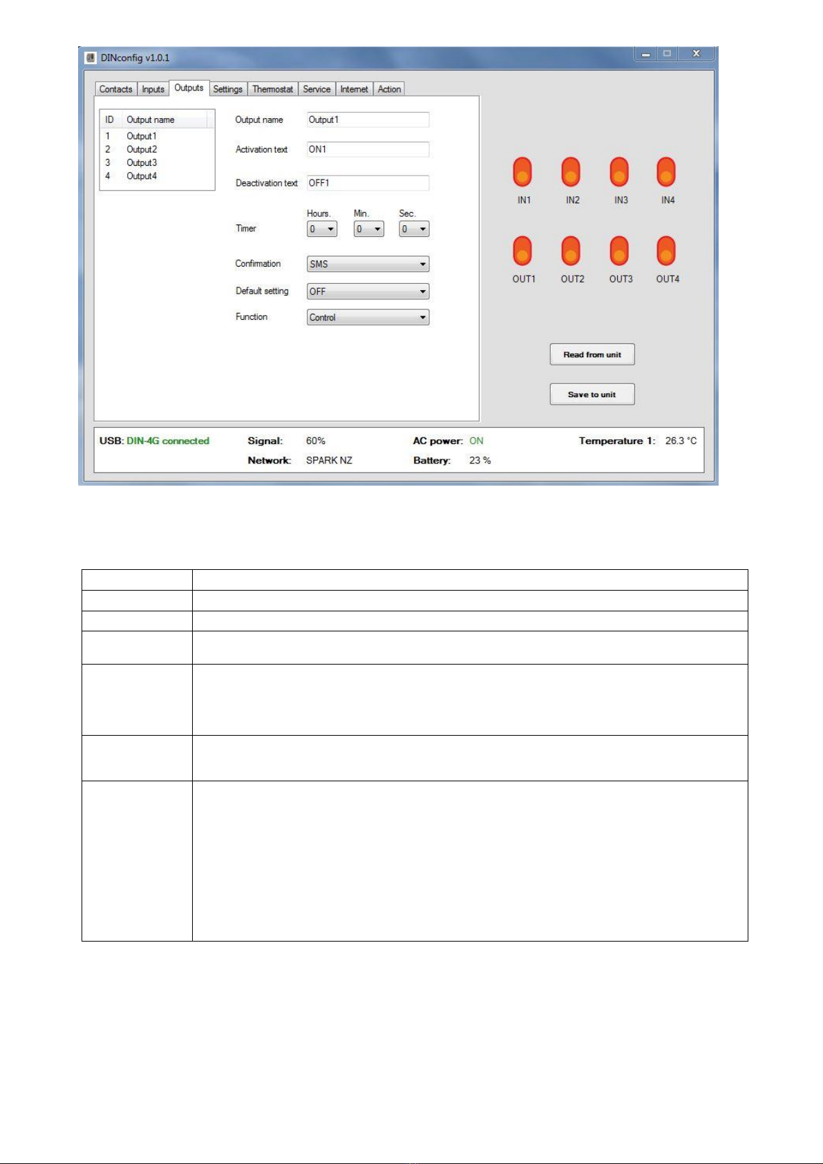
Outputs In this tab can be set all parameters for outputs include name, switching commands, timer, function etc.
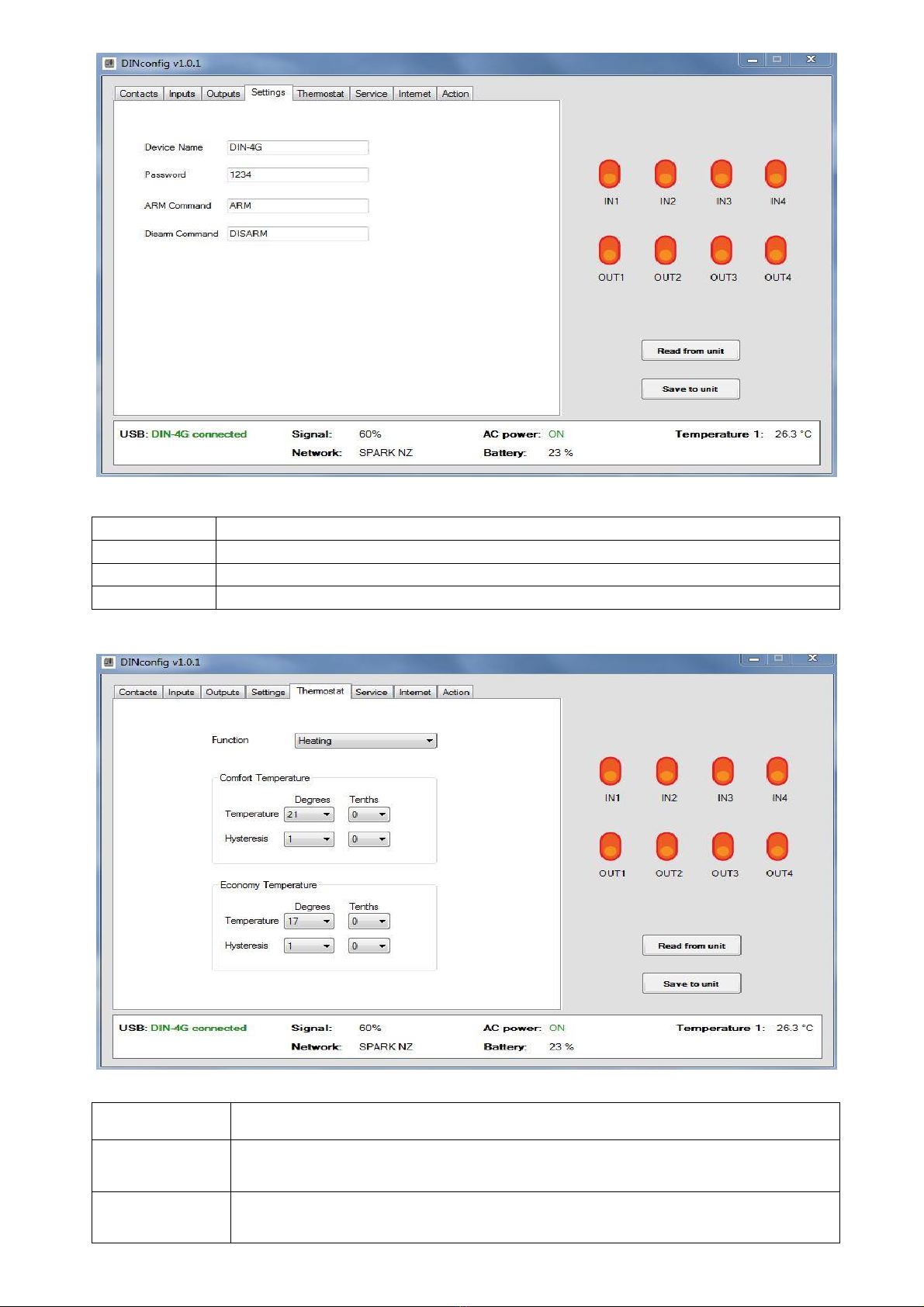
Settings In this tab can be set device name, password, and controlling commands
Thermostat In this tab can be set the thermostat function and temperature for comfort or economy function
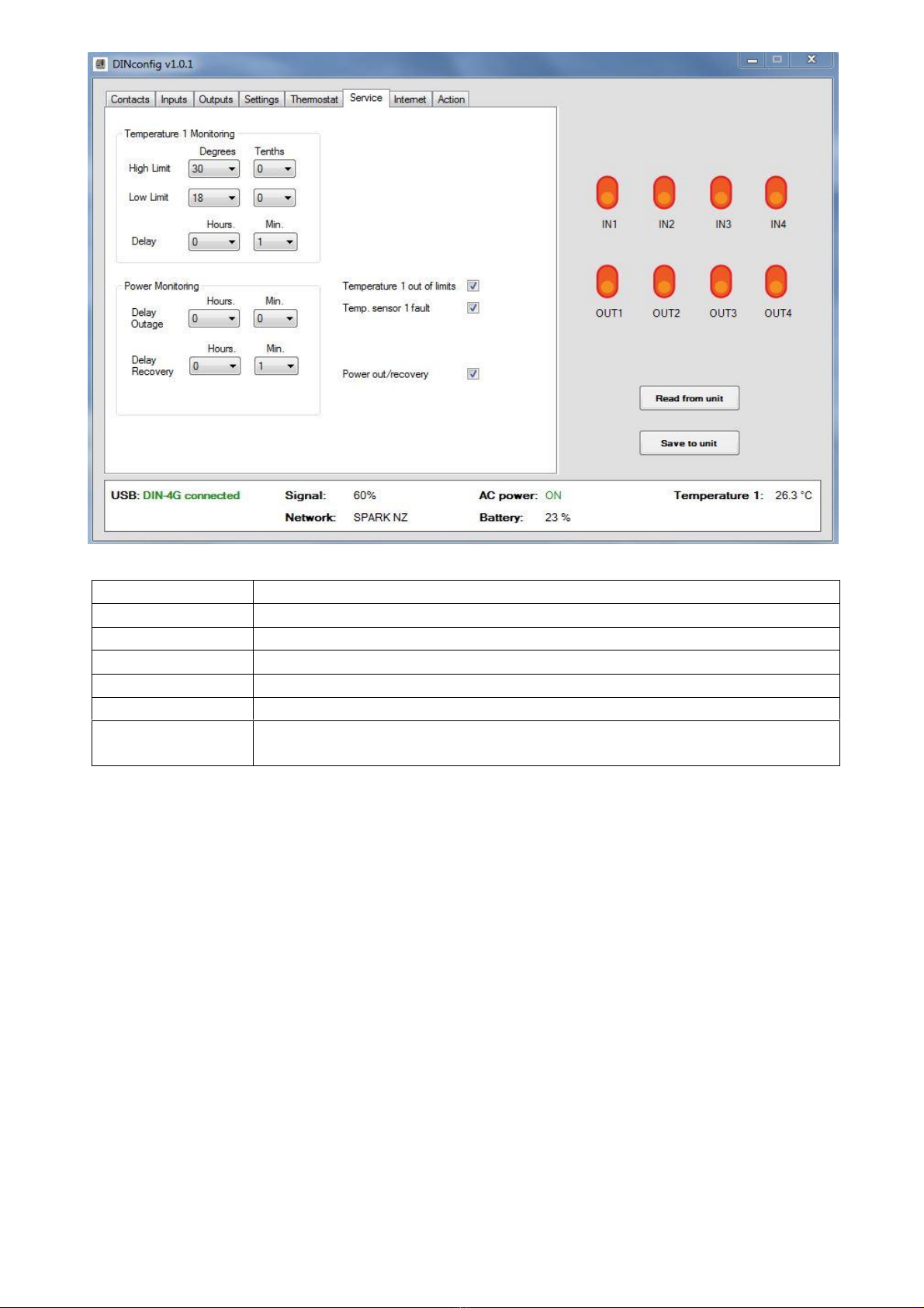
Service In this tab can be set notification to service numbers if power voltage or temperature is out of set limits
Internet In this tab can be set parameters for future internet server function
Action In this tab is possible reset setting to default, save or upload setting from or into file, upgrade firmware and live status
c of network signal, firmware etc.

Setting DIN-4G communicator via PC configuration software
Tab 1 – Contacts:
ID
The position of users in the system
Username
Set username
Phone number
Setting phone number of users
Inputs 1,2,3,4
Setting inputs 1,2,3,4 notification options
SMS
The activation of input will be reported via SMS
Call
The activation of input will be reported via Call
Outputs 1,2,3,4
Setting permissions to control outputs Set the number to control relay 1 or relay 2 via call.
SMS
The user phone number can control output via SMS without password
Call
The user phone number can control output via call (*To switching via call the call must be cut after hearing two
rings ** for output setting see the Tab3) ( for call condition see page 13)
A/D SMS
The user phone number can ARM and DISARM the communicator via SMS without password
A/D Call
The user phone number can ARM and DISARM the communicator via Call (*To switching via call the call must
be cut after hear two rings **the authorised number must have switched ON the call id on the phone)
Service
The user phone number will be receiving service SMS reports (see the service Tab6 for setting of parameters
page 8 )
NOTE: To load setting of user number into the table click on the user ID position
NOTE:2 To save all settings to the communicator click to “Save to unit” button

Tab2 - Setting of inputs:
Input name
Setting input name
Activation text
Text which will be send when input activated (connected to GND)
Deactivation text
Text which will be send when input deactivated (disconnected from GND)*the deactivation SMS text send only if
logic setting is set to NC or status change
Regime
ARM / DISARM =SMS send only if communicator in arm mode
24 Hour = the input always sends an SMS even if it is disarmed
Perform A/D = input can be used to Arm or Disarm the communicator from external device (Burglar alarm,
RFID reader, fingerprint etc.) *if input connected to GND, the communicator is disarmed when not connected to
GND, is arm. **This function work only if Logic set to status change
Logic
NO= Activation text SMS send when input connected to GND
NC= Deactivation text SMS send when input disconnected from GND
Status change= Activation text SMS send when input connected to GND and deactivation text SMS send when
input disconnected from GND
Delay
Setting the delay time for input (timer how long must be GND connected or disconnected to or from GND to
allow input triggered
Block
Input will be blocked for pre-set time after triggered to prevent send another SMS in case the input has been
triggered multiple times
Function
Monitoring = Input reporting changes to phone numbers
Thermostat = When the input is activated, the thermostat change status to economy or comfort mode.
Siren = When the input is activated, the output will switch if is set for siren function (the output with the siren
function is switched off only by a timer or by the user).

Tab3 – Setting of outputs:
Output name
Setting output name
Activation text
SMS command which will switch the output ON
Deactivation text
SMS command which will switch the output OFF
Timer
The output will be switched ON for the pre-set time. To control output ON/OFF only, the timer time must be set
to a value 0:0:0
Confirmation
SMS = After the output switched on or off via dialling or SMS the unit will confirm switching via SMS to the
same number
Call = After the output switched on or off via dialling or SMS the unit will confirm switching via: call back to the
same number
OFF = The confirmation is switched off
Default setting
ON =If communicator rebooted or switched on the output default status will be ON
OFF = If communicator rebooted or switched on the output default status will be OFF
Last status = If communicator rebooted or switched on the output will remain in status before restart
Function
Control= the output is controlled only the user (SMS message or by ringing).
Thermostat= the output regulates the temperature (see “Thermostat” tab5).
Siren = the output will turn on when the input activated and have function siren switched on ( the output will turn
off according the timer setting.
Signalling operation= mode designed for connection of an external LED that signals via flashing the status of
network or arm mode (example indicator light at the front door). Flashing types: Flashing fast = signal failure. Lit
briefly - goes out - on = monitoring on. Off -flashes briefly - off monitoring off
Signalling ARM mode = If the communicator in ARM mode the output is on
Signalling loss of network = if communicator lose network signal the output will switch on
Signalling temp. out of limits= if the measured temperature outside the set limits, the output is ON.
Temperature limits can be set on the tab6 service

Tab4 – Setting:
Device Name
To set device name (every SMS will start with this name)
Password
To set 4-digit password
ARM Command
To set command for arming the communicator
DISARM Command
To set command for disarming the communicator
Tab 5 – Thermostat setting:
Function
Heating =Regulates heating
Colling = Regulates Colling
Comfort temperature
Temperature = Set the required temperature for comfort heating / cooling.
Hysteresis = Set the temperature tolerance
Economy temperature
Temperature = Set the required temperature for economy heating / cooling.
Hysteresis = Set the temperature tolerance

Table 6 – Service setting:
Temperature Monitoring
Set the high and low temperature limits for notification via SMS to service number
Delay
Set the delay for sending notification when temperature out of limits (e.g. automatic defrost)
Power Monitoring
Set the notification via SMS in the event of a main power failure to service number
Delay Outage
Set the delay for sending notification when main power failure
Delay Recovery
Set the delay for sending notification when main power recovered
Temperature out of limits
Set ON notification via SMS to service number when temperature is out of set limits
Temperature sensor fault
Set ON notification via SMS to service number if temperature sensor fails
Power out/recovery
Set ON notification via SMS to service number when power supply voltage failure/recovery
* Service notifications will be send only to the service numbers
* if set all zeros there is no delay and the notification will be send immediately.
Tab7 – Internet: not used in this version

Tab8 – Action:
Read from unit
Will load all setting from the unit into software
Save to unit
Will save all setting from software to the unit
Read from file
Will load all saved setting from the file into software
Save to file
Will save all setting from software into file
Reset setting
All setting will be deleted, and unit will go to default
Firmware update
Will allow you to upgrade firmware from file
SMS Commands
Principles for using SMS commands:
•Each SMS command must include at the beginning the password. E.g. to determine the status send SMS: "1234 status"
•SMS commands are not case sensitive. E.g. command to determine the status, you can send STATUS / status / Status
•If possible, always use the DIN-4G PC configuration software, it’s easy and intuitive
Table 9 - SMS commands:
STATUS
Determines the current status of the communicator (network operator, signal strength,
temperature if the temperature sensor is connected and number of alarms since the last
activation)
SET DEFAULT VALUES
Restores the default settings of communicator. The phone numbers are not deleted.
NUMBERS?
List of all programmed phone numbers.
NUM1
Stores the phone number to the list. Example.: NUM1 021123456
DELNUM1
Delete the number 1 from the list.
CLEAR ALL NUMBERS
Delete all programmed phone numbers.
SETNUM1 ABCDEFGHIJ
Change setting for number1 see table 11
SETIN1 ABCDEFGHIJ
Change of input1 setting see table 11.
INPUTS?
List of current input settings
SETOUT1 ABCDEFGHI
Change of output1 setting see table 10
OUTPUTS?
List of current output settings
SETTHERM ABCDEFGHIJKLMNO
Change of thermostat setting see table 13.
SETTEMP ABCDEFGHIJK
Setting of monitoring temperature limits via SMS see table 14.
SETPWR ABCDEFG
Setting of monitoring power supply voltage via SMS see table 15.

Table 10- Storing the users phone numbers:
The DIN-4G Communicator can store up to 10 user mobile numbers which can be contacted via TXT or call if any inputs activated,
temperature change or power supply fail and all stored users can control outputs via call
Command:
NUM1 to NUM10, send SMS: 1234 NUMX (replace X for corresponding user number position)
Example :
1234 NUM1 +6421123456 means that the number one receives alarm information from input 1,
DELNUM1 to DELNUM10
Delete programmed number from dedicated position.
* A new number will overwrite old number
Table 11 - Setting of telephone numbers:
Command:
SETNUM1 to SETNUM10, send SMS: SETNUMX ABCDEFGHIJ (replace X for user number position)
Parameter A
A=0 – input1 does not send SMS or call the number
A=1 – input1 report activation via SMS to the number
A=2 – input1 report activation via CALL to the number
A=3 – input1 report activation via SMS and CALL to the number
Parameter B
B=0 – input2 does not send SMS or call the number
B=1 – input2 report activation via SMS to the number
B=2 – input2 report activation via CALL to the number
B=3 – input2 report activation via SMS and CALL to the number
Parameter C
C=0 – input3 does not send SMS or call the number
C=1 – input3 report activation via SMS to the number
C=2 – input3 report activation via CALL to the number
C=3 – input3 report activation via SMS and CALL to the number
Parameter D
D=0 – input4 does not send SMS or call the number
D=1 – input4 report activation via SMS to the number
D=2 – input4 report activation via CALL to the number
D=3 – input4 report activation via SMS and CALL to the number
Parameter E
E=0 – number does not control output 1
E=1 – number control the output 1 via SMS
E=2 – number control the output 1 via CALL
E=3 – number control the output 1 via SMS and CALL
Parameter F
F=0 – number does not control output 2
F=1 – number control the output 2 via SMS
F=2 – number control the output 2 via CALL
F=3 – number control the output 2 via SMS and CALL
Parameter G
G=0 – number does not control output 3
G=1 – number control the output 3 via SMS
G=2 – number control the output 3 via CALL
G=3 – number control the output 3 via SMS and CALL
Parameter H
H=0 – number does not control output 4
H=1 – number control the output 4 via SMS
H=2 – number control the output 4 via CALL
H=3 – number control the output 4 via SMS and CALL
Parameter I
I=0 – number does not control arm/disarm
I=1 – number control the arm/disarm via SMS
I=2 – number control the arm/disarm via CALL
I=3 – number control the arm/disarm via SMS and CALL
Parameter J
E=0 – number does not receive service SMS
E=1 – number will receive service SMS
Example:
SETNUM1:1000200001 means that the number1 receives activation information via SMS only from input 1,
control output is on only via call for output1, call control ARM/DISARM is off and service SMS report is
activated.

Table 12 - Digital input setting:
Command:
SETIN1 to SETIN4, send SMS: SETINX ABCDEFGHIJ (replace X for i corresponding input )
Parameter A
A = 0 – Input is subject to activation / deactivation communicator
A = 1 – Input is a 24-hour monitoring (permanent watch).
A = 2 – Input is activation / deactivation input (ARM / DISARM)
Parameter B
B = 0 – Input reacts to a connection to GND
B = 1 – Input reacts to a disconnection from GND
B = 2 – Input reacts to the any status change
Parameter C D
Input delay – minutes (enter 00 to 59, if you do not use a delay, enter value to 00)
Parameter E F
Input delay – seconds (enter 00 to 59, if you do not use a delay, enter value to 00)
Parameter G
Input delay – milliseconds (enter 0 to 9 corresponds to 100ms to 900ms, if you do not use a delay, enter value
to 0)
Parameter H I
Input blockage – minutes (enter 00 to 60, if you do not use a blockage, enter value to 00) Input will be blocked
for pre-set time after triggered
Parameter J
J = 0 – Input does not have a special function
J = 1 – Input has thermostat function
J = 2 – Input has siren function
Example:
SETIN1 1100002020 means that input is under continuous monitoring (24h), inputs react to GND connection,
, input delay is 200 milliseconds, after an activation the input is blocked for 2 minutes and no special function
assigned.
Table 13 - Output settings:
Command:
SETOUT1 to SETOUT4 send SMS: SETOUTX ABCDEFGHI (replace X for corresponding output)
Parameter A B
Output timer hours – (enter 00 to 59, if you do not use a timer, enter value to 00)
Parameter C D
Output timer minutes – (enter 00 to 59, if you do not use a timer, enter value to 00)
Parameter E F
Output timer seconds – (enter 00 to 59 if you do not use a timer, enter value to 00)
Parameter G
G = 0 – SMS (after the output switched on or off via CALL or SMS the unit will confirm switching via SMS)
G = 1 – CALL (after the output switched on via CALL or SMS the unit will confirm switching via CALL)
G = 2 – No confirmation
Parameter H
H = 0 – Output state is OFF if communicator restart
H = 1 – Output state is ON if communicator restart
H = 2 – Output state is the last know state before communicator restart
Parameter I
I = 0 – Output does not have a special function
I = 1 – Output has Thermostat function
I = 2 – Output has siren function
I = 3 – Output has Signalling operation function
I = 4 – Output has Signalling ARM mode function
I = 5 – Output has Signalling loss of network function
I = 6 – Output has Signalling temp. out of limits function
Example:
SETOUT1: 000000200 means the timer is off and the output can be switched ON or OFF, the status change of
output is not confirmed, after restart the output stay off and output does not have a special function.

Table 14 - Setting the thermostat:
Command:
SETTHERM, send SMS: SETTHERM ABCDEFGHIJKLMNO
Parameter A
A = 0 - Thermostat is in the heating mode
A = 1 - Thermostat is in cooling mode
Parameter B
Comfort temperature - sign. (can set the + or -)
Parameter C
Comfort temperature - hundreds °C. (can set 0-1)
Parameter D
Comfort temperature - tens °C. (can set 0-9)
Parameter E
Comfort temperature - units °C. (can set 0-9)
Parameter F
Comfort temperature - tenths °C. (can set 0-9)
Parameter G
Comfort temperature hysteresis - units °C. (can set 0-9)
Parameter H
Comfort temperature hysteresis - tenths °C. (can set 0-9)
Parameter I
Economy temperature - sign. (can set the + or -)
Parameter J
Economy temperature - hundreds °C. (can set 0-1)
Parameter K
Economy temperature - tens °C. (can set 0-9)
Parameter L
Economy temperature - units °C. (can set 0-9)
Parameter M
Economy temperature - tenths °C. (can set 0-9)
Parameter N
Economy temperature hysteresis - units °C. (can set 0-9)
Parameter O
Economy temperature hysteresis - tenths °C. (can set 0-9)
Example:
SETTHERM: 0+035001+025001 means the thermostat is in heating mode, comfort temperature is set to
+35.0 °C, economy temperature is set to +25.0 °C and hysteresis set to 1°C for comfort and economy
temperature. In other words: the thermostat stops heating to 35.0 °C and starts heating at 25.0 °C.
* The comfort and economy temperature can be set in the range of -55.9 to +124.9 ° C.
Table 15 - Setting the temperature monitoring notification limits:
Command:
SETTEMP, send SMS: SETTEMP ABCDEFGHIJK
Parameter A
A = 0 - Exceeding temperature limits notification via SMS is OFF
A = 1 - Exceeding temperature limits notification via SMS is ON
Parameter B
Upper limit of temperature monitoring - sign. (can set the + or -)
Parameter C
Upper limit of temperature monitoring - hundreds °C. (can set 0-1)
Parameter D
Upper limit of temperature monitoring - tens °C. (can set 0-9)
Parameter E
Upper limit of temperature monitoring - units °C. (can set 0-9)
Parameter F
Upper limit of temperature monitoring - tenths °C. (can set 0-9)
Parameter G
Lower limit of temperature monitoring - mark. (can set the + or -)
Parameter H
Lower limit of temperature monitoring - hundreds °C. (can set 0-1)
Parameter I
Lower limit of temperature monitoring - tens °C. (can set 0-9)
Parameter J
Lower limit of temperature monitoring - units °C. (can set 0-9)
Parameter K
Lower limit of temperature monitoring - tenths °C. (can set 0-9)
Example:
SETTEMP: 1+0300+0180 means that the monitoring of temperature is ON upper limit is 30.0, lower limit is 18.0,
SMS notification will be sent if the temperature drops below 18 °C or temperature goes above 30 °C
* The temperature can be monitored in the range of -55.9 to +124.9 ° C.
Table 16 - Setting the power supply monitoring notification:
Command:
SETPWR, send SMS: SETPWR ABCDEFG
Parameter A
A = 0 - Exceeding power supply limits notification via SMS is OFF
A = 1 - Exceeding power supply limits notification via SMS is ON
Parameter B
Outage power supply monitoring delay hours. (can set 0-4)
Parameter C D
Outage power supply monitoring delay minutes. (can set 0-60)
Parameter E
Recovery power supply monitoring delay hours. (can set 0-4)
Parameter F G
Recovery power supply monitoring delay minutes. (can set 0-60)
Example:
SETPWR: 1130100 means that the monitoring of power supply is ON. Outage delay set for one hour and thirty
minutes and recovery delay set for one hour.
* if set all zeros there is no delay and the notification is send immediately.

Controlling ARM/DISARM and Output via Call
Control ARM/DISARM and switching output can be operated free of charge via call. By call means dialling phone number of communi-
cator and wait for one or two whole tones, then it is necessary to end the call.
Function of call control can be used after the following settings:
Condition of controlling input ARM/DISARM via Call:
- In the setting of the telephone numbers (tab1) must be tick box A/D call or if setting via SMS command (table 11) parameter I must be
set 2 or 3
Condition of controlling output via Call:
- In the setting of the telephone numbers (tab1) must be tick box Call under any output or if setting via SMS command (table 11) pa-
rameter E,F,G,H must be set 2 or 3
- the communicator will switch change status ARM/DISARM only after dialling phone number of communicator and wait for one or two
whole tones, then it is necessary to end the call.
- the output will switch ON only after dialling phone number of communicator and wait for one or two whole tones, then it is necessary
to end the call.
- In the output setting (tab3), is possible set confirmation of switching via SMS or call
If it is allowed confirmation call, the communicator will call back when you turn the output ON when the output turn OFF this is not con-
firmed call back. When confirmation SMS set, will send SMS in both ON and OFF.
Reset a forgotten password
Reset a forgotten password:
If you forget the password for SMS, you can reset default password (the default password is 1234) as follows:
1. Disconnect power supply and USB from DIN-4G.
2. Connect power supply to DIN-4G and wait to unit connect to the network (blue LED flashing)
3. Send SMS to the number of the SIM card in DIN-4G, which contains only IMEI number (No password or command only IMEI)
* The IMEI must be sent to the communicator within 3 minutes after the power supply connected
4. DIN-4G password is now restored to 1234
Guidelines for Safe and efficient use:
Please read this information before using your DIN-4G Communicator. These instructions are intended for your safety. Please follow
these guidelines. If the product has been subject to any of the conditions listed below or you have any doubt as to its proper function,
make sure you have the product checked by a certified service partner before using it. Failure to do so might entail a risk of product
malfunction or even a potential hazard to your health.
Recommendations for Safe use of product:
•Always treat your product with care and keep it in a clean and dust-free place.
•Do not expose your product to liquid or moisture or humidity.
•Do not expose your product to extreme high or low temperatures.
•Do not drop, throw or try to bend your product.
•Do not attempt to disassemble or modify your product. Only authorised personnel should perform service.
•Do not use your product in an area where a potentially explosive atmosphere exists.
Antenna:
The DIN-4G Communicator has an antenna. Use of antenna devices not marketed by Pacific GSM Limited specifically for this model
could damage your DIN-4G Communicator, reduce performance, and produce SAR levels above the established limits (see below).
Radio Frequency (RF) Exposure and Specific Absorption Rate (SAR):
The DIN-4G Communicator is a low-power radio transmitter and receiver. When it is turned on, it emits low levels of radio frequency
energy (also known as radio waves or radio frequency fields).
Governments around the world have adopted comprehensive international safety guidelines, developed by scientific organizations,
through periodic and thorough evaluation of scientific studies. These guidelines establish permitted levels of radio wave exposure for the
general population. The levels include a safety margin designed to assure the safety of all persons, regardless of age and health, and to
account for any variations in measurements. Specific Absorption Rate (SAR) is the unit of measurement for the amount of radio fre-
quency energy absorbed by the body. The SAR value is determined at the highest certified power level in laboratory conditions, but the
actual SAR level of the DIN-4G Communicator while it is operating can be well below this value. This is because the DIN-4G Communi-
cator is designed to use the minimum power required to reach the network. Variations in SAR below the radio frequency exposure
guidelines do not mean that there are variations in safety. While there may be differences in SAR levels among 4G Communicators, all
Pacific GSM communicators models are designed to meet radio frequency exposure guidelines

Disposal of old Electrical and Electronic Equipment:
This symbol indicates that all electrical and electronic equipment included shall not be treated as household waste. Instead it
shall be left at the appropriate collection point for recycling of electrical and electronic equipment. By ensuring this product is
disposed of correctly, you will help prevent potential negative consequences for the environment and human health, which
could otherwise be caused by inappropriate waste handling of this product. The recycling of materials will help to conserve
natural resources. For more detailed information about recycling this product, please contact your local city office, your
household waste disposal service or the shop where you purchased the product.
End User Licence Agreement:
This wireless device, including without limitation any media delivered with the device, (“Device”) contains software owned by Pacific
GSM Limited and its third-party suppliers and licensors (“Software”). As user of this Device, Pacific GSM Limited grants you a non-
exclusive, non-transferable, non-assignable license to use the Software solely in conjunction with the Device on which it is installed
and/or delivered with. Nothing herein shall be construed as a sale of the Software to a user of this Device. You shall not reproduce,
modify, distribute, reverse engineer, decompile, otherwise alter or use any other means to discover the source code of the Software or
any component of the Software. For avoidance of doubt, you are at all times entitled to transfer all rights and obligations to the Software
to a third party, solely together with the Device with which you received the Software, provided always that such third party agrees in
writing to be bound by these rules. You are granted this license for a term of the useful life of this Device. You can terminate this license
by transferring all your rights to the Device on which you have received the Software to a third party in writing. If you fail to comply with
any of the terms and conditions set out in this license, it will terminate with immediate effect.
Disclaimer:
This device is designed for indoor use only unless protected in appropriate enclosure. The 4G Communicator is reliant on adequate
4G/3G coverage. In the event of inadequate or no 4G or 3G coverage, Pacific GSM Limited cannot be held liable for any damages.
The GSM Communicator was tested with SIM cards provided by “Vodafone NZ, Spark NZ, 2Degrees NZ, Telstra AU, Optus AU, Voda-
fone AU, AT&T USA, T mobile USA”. Pacific GSM Limited cannot be held liable for any malfunction with the use of other SIM cards.
Only use auxiliary equipment tested and approved by Pacific GSM Limited. Do not attempt to take apart, open, service, or modify the
hardware device. Doing so could present the risk of electric shock or another hazard. Any evidence of any attempt to open and/or mod-
ify the device, including peeling punching, or removal of any labels, will void the Limited Warranty. Never pass security code or the
mobile number of the Communicator to an unauthorised third party. All rights reserved. Except as expressly provided herein, no part of
this manual may be reproduced, copied, transmitted, disseminated, downloaded or stored in any storage medium, for any purpose with-
out the express prior written consent of Pacific GSM Limited. Information in this document is subject to change without any notice. Pa-
cific GSM Limited reserves the right to change or improve its products and to make changes in the content without obligation to notify
any person or organization of such changes or improvements. Visit the Pacific GSM Web site (www.pacificgsm.com) for current updates
and supplemental information concerning the use and operation of this and other Pacific GSM products.
Warranty:
Subject to the condition of this Limited Warranty, Pacific GSM Limited warrants this product to be free from defects in design, material
and workmanship at the time of its original purchase by a customer. This Limited Warranty will last for a period of two year as from the
original day of purchase and for a period of one year for all original accessories (aerial). The warranty does not cover any damages
caused due incorrect installation and the use of any auxiliary devices not approved by Pacific GSM Limited.
DIN-4G complies with requirements of the following regulations:
•EN 55032:2015
•EN 61000-6-2:2005
•EN 61000-4-2:2009 –criterion A
•EN 61000-4-3:2006 –criterion A
•EN 61000-4-4:2012 –criterion B
•EN 61000-4-5:2014 –criterion A
•EN 61000-4-6:2014 –criterion A
•EN 61000-4-11:2004 –criterion A
•EN 60950-1:2006
•AS/NZS 60950.1:2015
•AS/CA S042-2015
Australia / New Zealand Responsible Supplier number E4647 R-NZ
Technical Support:
Pacific GSM Limited
Contact No: +64 9 948 476 2 +64 21-476747
E-mail: info@pacificgsm.co.nz
Web: www.pacificgsm.com
© Published: 25 April 2022 by Pacific GSM Limited
No part of this booklet may be reproduced without written permission
Table of contents
Other Pacific GSM Cell Phone manuals