Pacific Teak Millworks CH-DO1-18 Installation instructions

INSTALLATION & OPERATION
INSTRUCTIONS
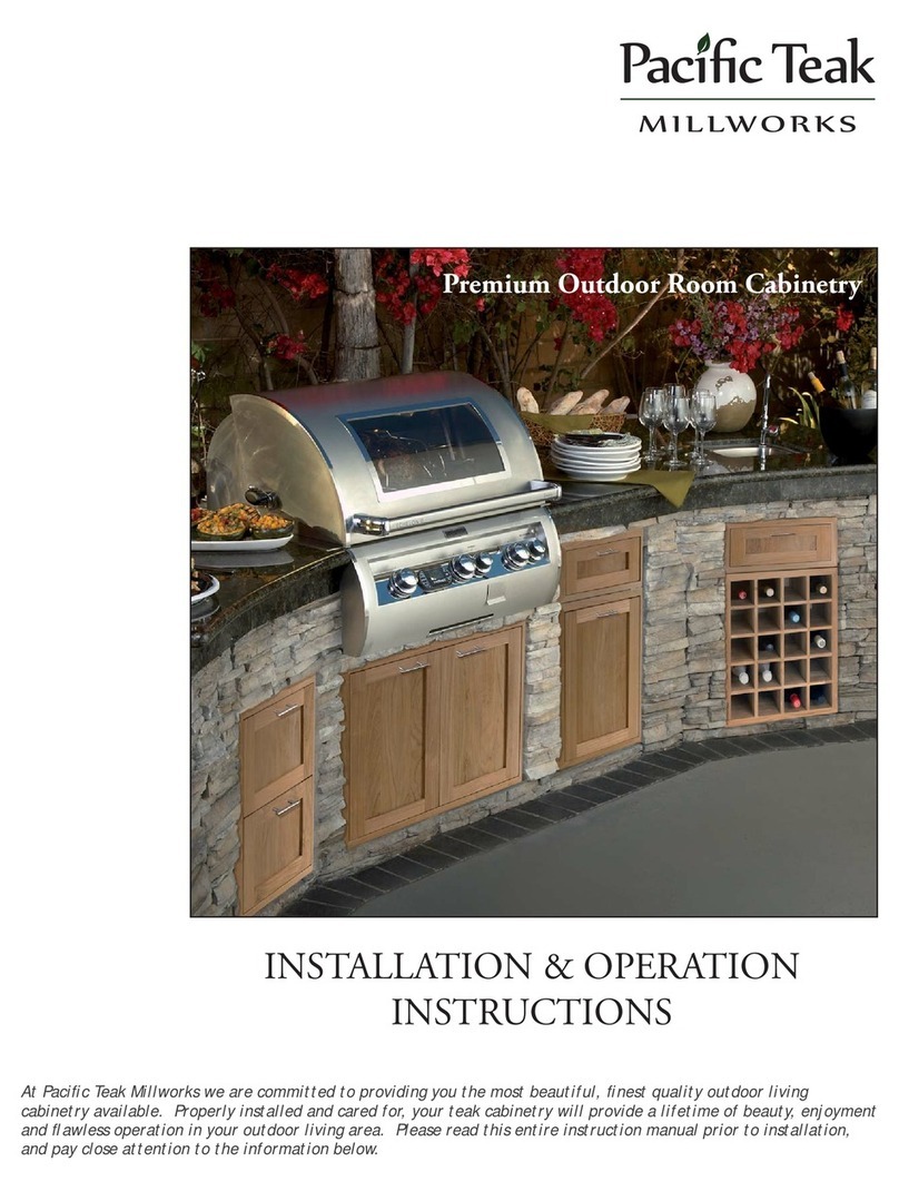
Premium Outdoor Room Cabinetry

Models A
(Width)B
(Height)C
(Depth)
CH-DO1-18; AD1-(18S/18C/18LR/ & 18LL) 17.25 21.25 3.25
CH-DO2-30; AD2-(30S/ 30C/ & 30L) 29.25 21.25 3.25
CH-DO2-34; AD2-(34S/ 34C/ & 34L) 33.25 21.25 3.25
CH-DR1H-18; UD1-(18S/ 18C/ & 18L) 17.25 7.25 20.25
CH-DR2V-18; UD2-(18S/ 18C/ & 18L) 17.25 21.25 20.75
CH-POTT-18; POTT-(18S/ 18C/ & 18L) 17.25 21.25 20.75
CH-POHDL-18; POHDL-(18S/ 18C/ & 18L) 17.25 21.25 23.75
CH-CO21-35; CO21-(35S/ 35C/ & 35L) 34.25 21.25 20.75
Cutout Dimensions
Installation Instr
u
ction
s
At Pacific Teak Millworks we are committed to providing you the most beautiful, finest quality outdoor living
cabinetry available. Properly installed and cared for, your premium teak outdoor cabinetry will provide
a lifetime of beauty, enjoyment and perfect operation in your outdoor room. Please read this entire
instruction sheet prior to installation, and pay close attention to the information below.
A
B
C
Important. Before you Begin:
•
!
WARNING: Drilling, sawing, sanding or machining wood products can expose you to wood dust, a substance
known to the State of California to cause cancer. Avoid inhaling wood dust or use a dust mask or other
safeguards for personal protection. For more information go to www.P65Warnings.ca.gov/wood.
• If your cabinets are to be installed in an island with a barbeque grill, consult your grill instructions regarding
“Clearances to Combustibles”. An insulated grill liner may be required.
• Be careful not to drop Door or Drawer Chassis’. It will damage the Outer Flange.
• Be careful not to damage the 2 black plastic expansion pin bushings on either side of the Hinge Cylinder.
• It is easier to install Doors after Door Chassis’ are installed in the island. Conversely, it is easier to install
Drawer Fronts before Drawer Chassis’ are installed.
• When drilling holes, always use sharp bits. Drill slowly and carefully, and do not apply excessive pressure on
the tip of the bit.
• When installing Door and Drawer Handles, always drill small pilot holes before drilling the final holes to avoid
chipping. Drill final holes from the front side to avoid chipping the face of the Door or Drawer Front.
• There are 2 sets of handle screws included with our hardware kits. The longer screws are for mounting handles on
the outer frames of all doors and drawer fronts. The smaller screws may be used if mounting handles in the center
panels of Shaker or Cottage style doors and drawer fronts.
• If the handle screw heads create a gap between the drawer box and drawer front, you may countersink the
screws into the drawer face frame about 1/8” or drill a partial or complete clearance hole in the drawer box
where the screws touch.
• If installing handles in the same location on multiple doors or drawer fronts, you can finish drilling the first
one, then use it as a template to drill the others. Line them up carefully and drill one at a time.
• Carefully drill pilot holes through mounting flanges at each screw location before installing screws. Installing
screws without pilot holes may cause wood to split which is not covered under your warranty.
• All hardware, including Hinges, Drawer Glides, Handles and Installation Hardware, is included with Door and
Drawer Chassis’, not with the Doors or Drawer Fronts.
• All cutout dimensions below are in inches and provide 1/4” total tolerance vertically and horizontally. Be
careful not exceed the dimensions shown.

a. Install Handles on the Doors and carefully set them aside.
b. Place the Door Chassis face down on a flat, smooth surface taking
care not to damage the flange. Press upward on the release Trigger
and detach The Hinge from the Mounting Plate.
c. With Top Clips fully open, press the Hinge Cylinder and Expansion
Pins into the matching holes in the Door until the Hinge Head is
completely flush with the Door surface. Be careful not to damage
the black plastic Pin Bushings.
d. Push the Clip Tops down to secure the Door.
Installing Drawers:
a. Install Handles on Drawer Fronts and carefully set them aside.
b. Place the Drawer or Combo Chassis at a comfortable working height. Take
care not to damage the beveled flange around the face of the chassis.
c. Your Soft-Close Drawer Glides include an orange release/ adjustment
mechanism (Figure 1.) at the front of the Glide with a blue release trigger
to remove the Drawer, and a blue Drawer adjusment which allows you to
level and adjust the height of the Drawer. Set the Drawer adjustment to
the fully “down” position by pushing the blue tab back toward the rear of
the drawer box.
d. With the Drawer box in the fully “closed” position, insert the Drawer Front
into the opening and against the drawer box. If your Chassis includes more
than one Drawer, start with the bottom Drawer and work your way up.
e. Center and align the Drawer Front. Place shims under and in the sides of
the Drawer Front to keep it in position.
f. Carefully secure the Drawer Front and install screws through the 2 middle, pre-drilled screw holes, and into
the two round plastic inserts located in the back side of the Drawer Front.
g. Repeat “e.” and “f.”above for each Drawer.
h. With all Drawer Fronts mounted, check the alignment and center gaps on all sides. To make side to side
adjustments, loosen the screws in the plastic cups, re-shim and reset screws. Use the blue adjustment
tabs on each Drawer Glide to raise or level Drawers.
i. When the Drawers are level and centered, pre-drill pilot holes, and secure the Drawer Fronts to the Drawer
Boxes using screws provided.
j. Remove the Drawers from the Chassis in the fully “open” position by depressing the blue triggers shown in
Figure 2. and lifting Drawers out. Carefully set Drawers aside.
k. Install the empty Drawer Chassis in the island using screws appropriate for your island material.
l. To re-install Drawers, extend the Drawer Glides out into the fully “open” position. Rest the Drawers on the
Glides, then push them into the Chassis until you hear them “click” into position.
Installing Doors:
Figure 1.
Adjustment Tab
Trigger
Figure 2.
Top Clip
Release Trigger
Note: When installing or removing hinges from a door, the hinge top clip must be completely in the “up”
position, and the hinge arm should be fully extended in the “door open” position as shown in Figure 2.
Note: To hide mounting screws, install them under the hinges, about 1/2” in front of the Hinge Plates.
e. Pre-drill installation holes in the Flanges, and install the Door Chassis into the island opening using screws
appropriate for your island material. Make sure the Chassis is level and square.
f. Attach Hinges and Door as a unit to the Hinge Plates with the Door in the “open” position. Engage the
metal Pin located under the front of each hinge arm into the hooks at the front of the hinge mounting
plate, then press down on the back of the Hinge body to lock in place.
g. Adjust Door alignment as shown on the next page.

Adjusting Doors:
33951 Valencia Place
Dana Point, CA 92629
info@pacificteakmillworks.com
www.pacificteakmillworks.com
IN2 519
This manual suits for next models
32
Table of contents
Other Pacific Teak Millworks Outdoor Furnishing manuals
Popular Outdoor Furnishing manuals by other brands

PHI VILLA
PHI VILLA E02GS008 Use and care guide

Kettler
Kettler FORMA II 0104703-0600 Assembly & operating instructions

Living Accents
Living Accents 8026900 quick start guide

toolport
toolport GG-L1-Q3 Assembly instructions

UBERHAUS DESIGN
UBERHAUS DESIGN 38115077 Operator's manual

Coopers of Stortford
Coopers of Stortford G358 Instructions for use