Pack Leader PRO-515 Quick start guide

PRO-515 WRAP AROUND LABELER
OPERATIONAL MANUAL
Serial Number:
Electricity: V HZ Φ

- 1 -
Table of Contents
Title Page
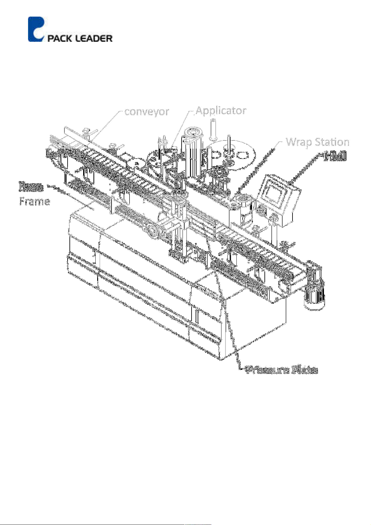
Machine Sub- Assemblies ........................................................................................................................... 3
Machine Dimensions................................................................................................................................... 4
Machine Specification ................................................................................................................................. 5
Machine Features........................................................................................................................................ 6
Specification of Label Reel .......................................................................................................................... 7
Safet Regulations ....................................................................................................................................... 8
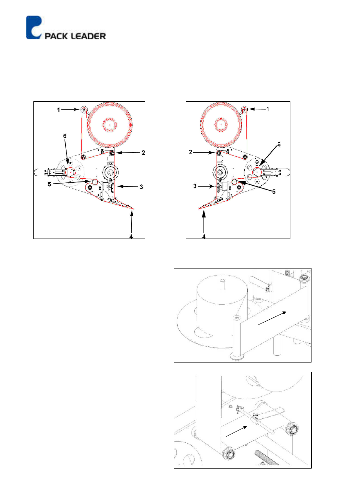
Label Applicator .......................................................................................................................................... 9
Guide Rail .................................................................................................................................................. 12
Position of Object Sensor .......................................................................................................................... 14
Parts Adjustments ..................................................................................................................................... 15
Label Sensor Position ................................................................................................................................ 18
Machine Operation ................................................................................................................................... 19
Touch Screen ............................................................................................................................................. 23
Trouble Shooting ....................................................................................................................................... 24
Electronic Diagram .................................................................................................................................... 26
HMI Frame ................................................................................................................................................ 27
Control Box Frame .................................................................................................................................... 28
Control Box Frame .................................................................................................................................... 29
Electronic Parts List ................................................................................................................................... 30
Applicator Exploded View ......................................................................................................................... 31
Applicator Exploded Part List .................................................................................................................... 32
Label Suppl Plate Assembl ..................................................................................................................... 33
Label Suppl Plate Assembl Part List ....................................................................................................... 34
Tension Bar Assembl ............................................................................................................................... 35
Applicator Motor Assembl ...................................................................................................................... 36
Base Paper Collect Driven Pulle Set ........................................................................................................ 37
Base Paper Collect Assembl .................................................................................................................... 38
Base Paper Collect Assembl Part List ...................................................................................................... 39
Label Lead Assembl 1 .............................................................................................................................. 40
Label Press Assembl ................................................................................................................................ 41
Label Lead Assembl 2 .............................................................................................................................. 42
Lever Sleeve Assembl .............................................................................................................................. 43
PU Roller Assembl ................................................................................................................................... 44
PU Roller Assembl Part List ..................................................................................................................... 45

- 2 -
Title Page
Label Peel Plate Assembl ......................................................................................................................... 46
Label Peel Plate Assembl Part List ........................................................................................................... 47
Label Sensor Base Assembl ..................................................................................................................... 48
Applicator Angle Adjustment Fixture Assembl ....................................................................................... 49
Applicator Angle Adjustment .................................................................................................................... 50
Applicator Angle Adjustment Part List ...................................................................................................... 51
Applicator Up/down Adjustment Assembl ............................................................................................. 52
Wrap Station Assembl ............................................................................................................................. 53
Frame of Wrap Station Assembl .............................................................................................................. 54
Driving Pulle Assembl ............................................................................................................................ 55
Driving Pulle Assembl Part List .............................................................................................................. 56
Driven Pulle Assembl ............................................................................................................................. 57
Wrap Station Up/Down Adjustment Assembl ......................................................................................... 58
Wrap Station Up/Down Adjustment Assembl Part List ........................................................................... 59
Pressure Plate Assembl ........................................................................................................................... 60
Pressure Plate Fixture Assembl ............................................................................................................... 61
Pressure Plate Adjustment Assembl ....................................................................................................... 62
Pressure Plate Adjustment Assembl Part List ......................................................................................... 63
Conve or Assembl ................................................................................................................................... 64
Conve or Assembl Part List ..................................................................................................................... 65
Bottle Separator Assembl ........................................................................................................................ 65
Conve or Front Side Plate Assembl ........................................................................................................ 66
Conve or Back Side Plate Assembl .......................................................................................................... 67
Spacing Pillar Assembl ............................................................................................................................. 68
Conve or Driven Pulle Assembl ............................................................................................................. 69
Conve or Motor Assembl ........................................................................................................................ 70
Guide Rail Bracket Set ............................................................................................................................... 71
Conve or Driving Pulle Assembl ............................................................................................................ 72
Bottle Separator Assembl ........................................................................................................................ 73

- 3 -
PRO-515 WRAP AROUND LABELING MACHINE
Machine Sub- Assemblies

- 4 -
Machine Dimensions

- 5 -
Machine Speci ication
.
Electricit
1. Voltage: 110V/220Vac
2. Frequenc : 50Hz/60Hz
3. Phase: Single
4. Power Consumption: 660W
Conve or Width 160mm(6 5/16”)
Speed Control 8 Levels Selection
Conve or Max Speed 20M/Minute
Dispensing Max Speed 40M/Minute
Labeling Head Driver Step Motor Drive
Label Length Min: 15mm (0.59’ ) Max:300mm (11.81’ )
Label Reel Inner 76mm (2.99’ )
Label Reel Outer Max: 375mm (14.76’ )
Space Between Label Min: 3mm (0.12’ ) OR More
Machine Dimension;
i. Length:2420 mm
ii. Width: 1380 mm
iii. Height: 1350 mm
Conve or Height: 880 mm (from floor)
Machine Weight: 200 Kgs.

- 6 -
Machine Features
The build-in instruction of the operation s stem is ver eas and well documented. This s stem
reduces the training time for the new operators who can immediatel increase the production
since an one can learn to operate it within few minutes.
The build-in Trouble shootings feature reduces the down time for s stem breakdown. Operator
can easil follow the instruction on the screen to solve the problems.
User- friendl design for setting label length, an different size of label can be easil detect with a
gentle touch. This unique setting can assure the accurac of each label length, so that it won't be
affected b the mismatch of length from previous memor setting (Since the space between each
label could has a slight difference, the error will accumulate during each labeling process). Beside
that, the set up process is ver simple for new operator.
With the function of label counter, ou can easil monitor the current status of labeled quantit
from the control screen.
With the batch counter, ou can preset the total labeling quantit . The machine will auto-stop
when it reach the preset quantit . This feature is useful for quantit management in the
production line.
With position set, ou can easil adjust the position of the label b setting a dela time to make
some adjustment on the label position.
Missing label auto-stop s stem can avoid an missing the label on products for manufacturers to
easil do their qualit control during the production process.
For different printing speed, printer timer can be set for different demands to assure the clarit of
the each print. (The printer is optional. All the control circuit for printer is preset for future
installation in all standard machines).
Eight speed selection for different working environment to meet the requirement of different
production lines.
Automatic start function reduces the setup time b simpl providing electricit , the s stem and it
will start operate b itself in the production line.
The conve or has a separator wheel to space each bottle apart from each other and ensure the
correct position for labeling. B adjusting the guide rail, different size of bottles can be labeled (for
production rate of 100 ~ 200 bottles per minute, use in- feed screw for fast and stable operation.)
Foot-stand designed with square-shapes for small footprint and castors for mobilit . It is read to
operate as a stand-alone machine or connected with other in-line machine for flexibilit
30 memor slots for convenient data retrieval and loading.

- 7 -
Speci ication o Label Reel
Base Paper Translucent
Reel Inner Diameter: 76 mm
Reel Outer Diameter: 370 mm
Interval of Label Min. 3 mm (between label)
Width of Base Paper Label Width + 4 mm
Width of Label 180 H Label Head – 10 ~ 180 mm
200 H Label Head – 10 ~ 200 mm
Length of Label 15 ~ 300 mm (Standard)
LEFT SIDE RIGHT SIDE
Standard

- 8 -
Sa ety Regulations
1. Make sure the hands are dr before to put on the plug. Especiall , in the food industries or in wet
working environment
Danger Safe
2. When the machine is running please beware of our clothes, hair, gloves or an thing, which is eas
caught on the conve or or running roller that ma cause injur .
3. Do not touch the conve or, roller or paper receive axis when machine is running
Inspection before Operation
1. Make sure the power is connected to right power source
2. Machine adjusted to product specification range
3. The height of label applicator adjusted in appropriate position
4. The guide rails adjusted to according the width of the product
5. Object sensor adjusted in right position
6. Label sensor adjusted in proper setting
7. Conve or is clear with no extra object
8. Separator wheel adjusted to accommodate the width of the product

- 9 -
Label Applicator
To put the labels in the label applicator, kindl follow the following instructions with diagrams:
Right applicator Left applicator
Standard
1 Put the roll of label on the tra and passes it
through the tension roller so it will not spin out
of control.
2 Fasten the tension clip after passing through
this point to ensure tension on the label strip
and avoid loose labels.

- 10 -
3 It is important for the labels to pass through the label
sensor slit for it detects the labels and controls the
dispensing of labels.
4 The dispensing plates peels the label from the base
paper for application on the objects.
5. The drive PU rubber roller pulls the base paper to position the labels. The aluminum pressure roller
must be locked in place with the PU roller in order to squeeze the paper and pull effectivel .

- 11 -
Wrong Right
Warning
If the aluminum roller is not tightl pressed against the drive PU roller, the labeling will be
inaccurate. Inaccurate label position causes inaccurate labeling. If the aluminum roller is
pressed too tight, it will cause the drive PU roller to wear and crack.
6. Wind the base paper around the 3 pillars at
the collection of the base paper. Wind it up
until there is some tension on. The paper
for proper pickup
A
B
B1
Loose squeeze
Aluminum pressure
roller
A1
Drive PU Roller

- 12 -
Guide Rail
Guide Rail: To guide the products in the right position or direction
Adjust guide rail width:
Put three object at position A, B and C align to reference side rail
Loose adjustment lock, C and D, then push adjustment side rail to close object.
Adjustment lock Guide rail
Adjustment side
Reference side

- 13 -
Warning
If the guide rail’s width is not adjusted to conform with the object’s dimensions, this will affect the
precision of the applied labels. So it is ver important to adjust the guide rails according to the objects
dimension. The margin must be minimal for the object to pass freel .
Right

- 14 -
Position o Object Sensor
1. If sensor move to too right side,
the label will comes out too late.
Then the bottle will have no label on it
2. If sensor move to too left side
there will have wrinkles on label
3. The proper position of sensor is
to make label comes out and sticks
on bottles’ surface at the right position
Pressure plate
Object sensor
Right
Left
Wrinkle

- 15 -
Parts Adjustments
1. Conve or Adjustment:
To adjust the tightness of the conve or belt, loosen the two nuts on the screws.
Turn CCW to loosen and CW to tighten. Make sure the conve or is centered for it will be nois if
not centered.
2. Wrap around station adjustment
To adjust wrap around station height: onl adjust screw C and D so ou can adjust wrap around
belt and pressure plate height.
Part name
A
Wrap around belt
B
Pressure plate
C
High and low adjust
D
High and low adjust
E
Frontward and backward adjust

- 16 -
To adjust wrap around station widths: As follow drawing show, put object between wrap around
belt and pressure plate. Adjust frontward and backward screw E, let pressure plate press object
with suitable pressure. Then turn on conve or to check object and be turned smoothl .
3. Wrap around belt adjustment: To adjust the tightness and centering the belt, adjust the screw A.
When adjusting, use onl small increments and let the belt run for a while to determine the final
position. A belt that is not centered will slip up or down.
Higher Lower

- 17 -
4. Paper press piece adjustment; First, loosen screw (A) turn the rod (2) CCW and hold it. Use our
other hand to tighten screw A and then release it.
5. OBJECT SENSOR
The object sensor is a fiber optic infra-red sensor use to detect the presence of bottle on the labeling
zone. If the sensor is not able to detect a bottle, adjust the intensit of the amplifier until the sensor is
able to trigger the applicator to appl a label.
Adjust the intensity of the infra red light if the
sensor fails to detect the object when it pass through
To set the sensor to instantaneous trigger (light on) or trigger after the object has passed
through (dark on).Normally set at dark on mode.
Red lit/ no object
Green lit/object is
present.

- 18 -
Label Sensor Position
1. Please follow the direction of diagram to install the label sensor
2. Kindl place the label through the detect point of label sensor
3. Adjust the sensitivit of label sensor to the appropriate position after the label is passed through
the label sensor

- 19 -
Machine Operation
Please follow the operation steps and instruction
1-1. Plug-in the appropriate power suppl voltage
1-2. Turn of the power (Turn on the emergenc stop switch if in “off” condition)
1-3. The displa will shows as diagram 1.
1-4. Press “Enter” to get into next diagram or wait for 3 seconds
2-1. Press “Guide Mode” for showing machine operation instruction
2-2 Press “Setting Mode” for set up machine information and speed
2-3 Press “Memor Mode” for memor setup.
2-4. Press “Labeling Mode” to enter diagram 3 or wait 5 seconds for next diagram
Diagram 1
Diagram 2
Table of contents
Other Pack Leader Industrial Equipment manuals
Popular Industrial Equipment manuals by other brands

Bosch
Bosch Rexroth LTH Technical information manual

Eaton
Eaton TE series Installation & service manual

Matrix
Matrix KS 200-1 Translation of the original instructions

ebatec
ebatec GS 81 operating instructions

Rexnord
Rexnord Falk NRTH B 1055 Installation & maintenance

Grizzly
Grizzly G0656P instruction manual

matev
matev TRL-3D 20 operating manual

SUHNER ABRASIVE
SUHNER ABRASIVE ROTOfera Technical document

IonSense
IonSense DART Ion Source 100-CE Operation manual

RINGSPANN
RINGSPANN EV 018 FEM-240M Installation and operating instructions

ATOMSTACK
ATOMSTACK MAKER R1 manual

Exmark
Exmark Lazer 126-7379 installation instructions