Paia Theremax 9505 Guide

062702 Theremax 1
(c) 1996 PAiA Electronics, Inc.
Portions of this document are excerpted from
an article appearing in the Feb 1996 issue of
Electronics Now magazine, copyright 1996,
and are reprinted by permission of the Publisher.
Model 9505
Assembly and Using Manual
Theremax
Since it's introduction to the general public in the late '20s, the Theremin
has been evocative in image and tone. Even eyes that had seen such
wonders as pictures flying through the air widened at the sight of a
musician producing sound using only a conductor's gestures. And it's pure
tones, able to stand out without distortion against even the full fortissimo of
a symphony orchestra, were like nothing anyone had ever heard before.
Was it a hit? You bet, theremin concerts were SRO in halls where
audiences were ordinarily sparse. The place of the Theremin in a "mod-
ern" orchestra was a given for such maestros as Leopold Stokowski, who
used one or more in numerous concerts of the Philadelphia Orchestra
during the late '30s. RCA thought that every cultured home would have
one, but for a lot of reasons things didn't work out quite like that.
Theremax employs the same heterodyneing principles as the original
Theremins and produces the classic sound while adding embellishments
made possible by the economy of transistors and Integrated Circuits. It
can function as a stand-alone instrument or as a gesture-sensing control-
ler for other musical instruments or in performance art applications.

062702
2 Theremax
ASSEMBLING THEREMAX
Before beginning assembly, go through the manual.
Look at the drawings. Feel the parts. You’re
naturally eager to plunge right in, but take a few
deep breaths first.
Notice that each step in the manual is marked with
a checkoff box like this:
DESIGNATION VALUE COLOR CODE
( ) R27 100 ohm brown-black-brown
Checking off each step as you do it may seem
silly and ritualistic, but it greatly decreases the
chance of omitting a step and also provides
some gratification and reward as each step is
completed.
Numbered figures are printed in the Illustrations
Supplement in the center of this manual. These pages
may be removed for easy reference during assembly.
THE CIRCUIT BOARD
Theremax is built on a single-sided solder masked circuit
board. No special preparation or cleaning is necessary
before assembly. The "top" of the board is the side that
is printed with component designations and parts are
mounted from this side. The "bottom" of the board is
also called the solder side and is masked with a
conformal coating to lessen the chance of solder bridges.
Solder pads are tin-lead plated for ease of soldering and
assembly.
TOOLS
You’ll need a minimum of tools to assemble the kit
- a small pair of diagonal wire cutters and pliers,
screwdriver, sharp knife, ruler, soldering iron and
solder.
Modern electronic components are small (in case you
hadn’t noticed) and values marked on the part are
often difficult to see. Another handy tool for
your bench will be a good magnifying glass. Also

062702 Theremax 3
use the magnifier to examine each solder joint as
it is made to make sure that it doesn’t have any of
the problems described in the SOLDERING section
which follows.
SOLDERING
Select a soldering iron with a small tip and a
power rating not more than 35 watts. Soldering
guns are completely unacceptable for assembling
solid state equipment because the large magnetic
field they generate can damage components.
Use only rosin core solder (acid core solder is for
plumbing, not electronics work). A proper solder
joint has just enough solder to cover the soldering
pad and about 1/16-inch of lead passing through it.
There are two improper connections to beware of:
Using too little solder will sometimes result in a
connection which appears to be soldered when
actually there is a layer of flux insulating the
component lead from the solder bead. This
situation can be cured by reheating the joint and
applying more solder. If too much solder is used
on a joint there is the danger that a conducting
bridge of excess solder will flow between adjacent
circuit board conductors forming a short circuit.
Accidental bridges can be cleaned off by holding
the board upside down and flowing the excess solder
off onto a clean, hot soldering iron.
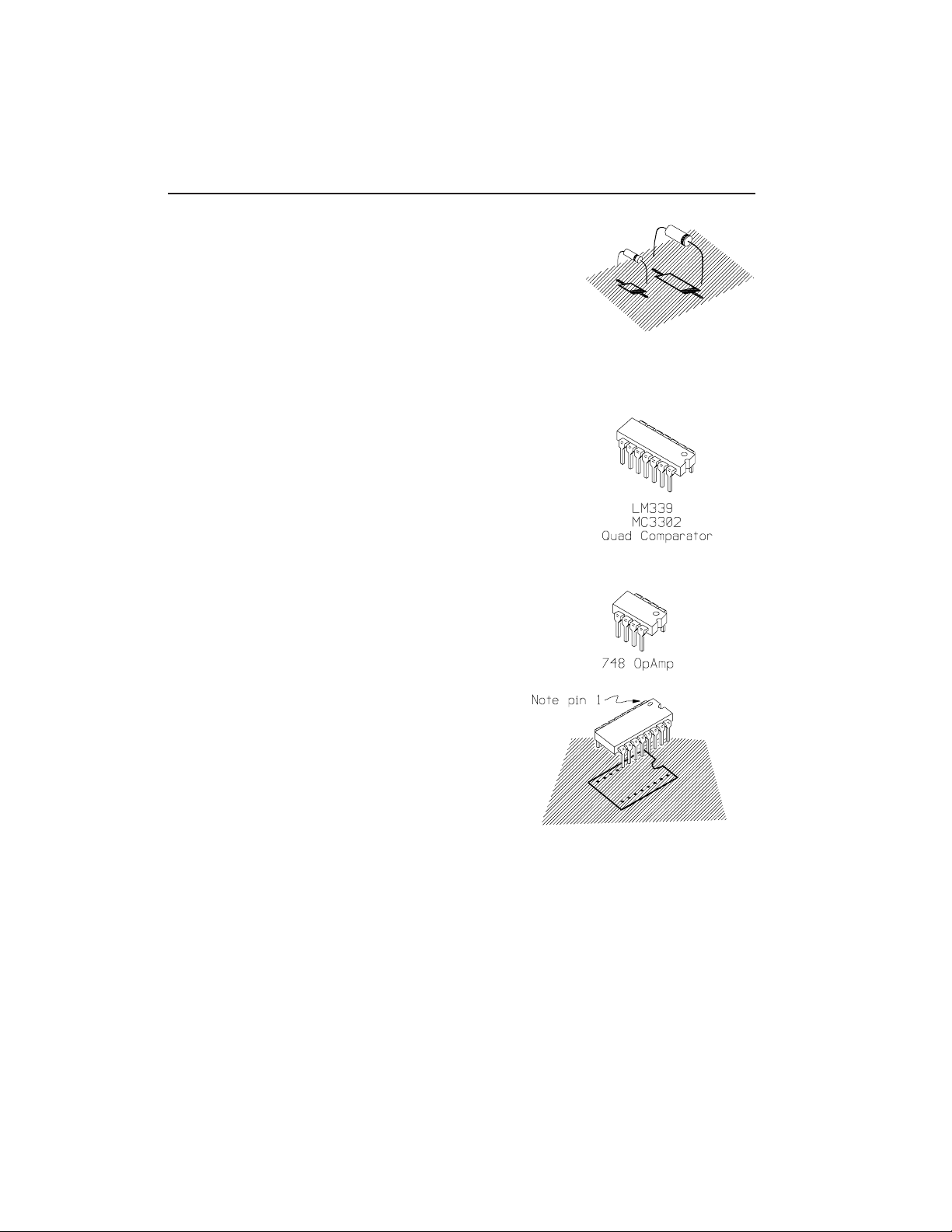
Use care when mounting all components. Never force
a component into place.
Tips from the Pros: Your first step should always be to check the parts list in this
manual (usually the last page). Hard as it is to admit that we make mistakes, it is not unheard of
for us to mispack the bag. We ship missing parts quick, but there's nothing more aggravating
than discovering a missing part in the middle of assembly, at 10:00 PM. Checking the parts
also gives you the opportunity to handle them, making sure you know what they are.
Look through the manual fully before you begin assembly, it wouldn't hurt to check the parts
supplied against the drawings in the manual. The more you think about what you're going to be
doing before you do it, the better.
Since the Tmax case requires some gluing and probably finishing, you may want to get to that
part early. Case Assembly begins on page 16.

062702
4 Theremax
WIRE JUMPERS
Assembly begins by forming and
installing the eight wire jumpers
indicated by bold lines on the circuit
board parts placement designators
and numbered in the illustration to
the right. For each jumper, cut a
length of the bare wire supplied by
measuring it against the distance
between the circuit board holes and
adding about 1/2". Bend 1/4" of
each end down and push through
the circuit board holes. Press the
jumper fully against the board and
solder both ends. Trim off excess
wire flush with the solder joint.
( ) As outlined above, form and
install the eight wire jumpers
used on the circuit board.
RESISTORS
Solder each resistor in place following the
parts placement designators printed on the circuit
board and the assembly drawing Fig 1. Note that
resistors are nonpolarized and may be mounted with
either lead in either of the holes in the circuit board.
Before mounting each resistor, bend its leads so
that they are at a right angle to the body of the
part. Put the leads through the holes and then
push the resistor firmly into place. Cinch the
resistor in place by bending the leads on the
solder side of the board out to an angle of about
45 degrees. Solder both ends of each resistor in
place as you install it. Clip each lead flush with
the solder joint as the joint is made.

062702 Theremax 5
DESIGNATION VALUE COLOR CODE A-B-C
( ) R1 100 brown-black-brown
( ) R22 1000 brown-black-red
( ) R23 1000 brown-black-red
( ) R56 1000 brown-black-red
listed below: 100k brown-black-yellow
( ) R71 ( ) R72 ( ) R73 ( ) R74
listed below: 10k brown-black-orange
( ) R11 ( ) R16 ( ) R41 ( ) R50
( ) R70
( ) R35 10 megohm brown-black-blue
( ) R46 10 megohm brown-black-blue
( ) R10 1500 ohm brown-green-red
( ) R15 1500 ohm brown-green-red
( ) R51 15k brown-green-orange
( ) R52 15k brown-green-orange
listed below 1megohm brown-black-green
( ) R24 ( ) R25 ( ) R54 ( )R57
( ) R43 2200 red-red-red
( ) R53 2200 red-red-red
( ) R42 220k red-red-yellow
listed below: 22k red-red-orange
( ) R39 ( ) R55 ( ) R58 ( ) R64
( ) R32 330 orange-orange-brown
( ) R63 330 orange-orange-brown
listed below: 3300 orange-orange-red
( ) R2 ( ) R7 ( ) R12 ( ) R19
( ) R31 39k orange-white-orange
( ) R62 39k orange-white-orange
( ) R44 4.7megohm yellow-violet-green
listed below: 47 yellow-violet-black
( ) R5 ( ) R6 ( ) R20 ( ) R21

062702
6 Theremax
DESIGNATION VALUE COLOR CODE A-B-C
( ) R28 470 yellow-violet-brown
( ) R67 470 yellow-violet-brown
( ) R68 470 yellow-violet-brown
( ) R26 4700 yellow-violet-red
( ) R45 4700 yellow-violet-red
( ) R59 4700 yellow-violet-red
listed below: 470k yellow-violet-yellow
( ) R27 ( ) R29 ( ) R40 ( ) R60
listed below: 47k yellow-violet-orange
( ) R30 ( ) R33 ( ) R34 ( ) R36
( ) R37 ( ) R38 ( ) R48 ( ) R49
( ) R61 ( ) R65 ( ) R66
listed below: 56k green-blue-orange
( ) R4 ( ) R9 ( ) R14 ( ) R18
listed below: 680 blue-grey-brown
( ) R3 ( ) R8 ( ) R13 ( ) R17
( ) R69
( ) R47 68k blue-grey-orange
OSCILLATOR COILS
The oscillator coils are housed in metal cans to
shield them from interaction with one another.
Notice that the coils can be mounted only one
way, with the case tabs going though the larger
holes in the pattern and the solder pins going
through the five smaller holes. The solder pins
may need to be straightened slightly to align with
the holes. Push the part into place until the
shoulder of the mounting tab rests on the surface
of the circuit board. Solder all five solder pins and
also bend the mounting tabs over on the conduc-
tors side of the board and solder one of them to
the conductor pad.
DESIGNATION TYPE
listed below: 796 kHz Oscillator Coils
( ) L1 ( ) L2 ( ) L3 ( ) L4

062702 Theremax 7
CERAMIC DISK AND MYLAR CAPACITORS
Many of the capacitors used in Theremax are
nonpolarized Ceramic Disk and Mylar types. For
all of these, either lead can go in either of the
holes in the circuit board. The leads of the
Ceramic Disk and Mylar capacitors are already
parallel to each other but still may need to be bent
slightly to match the spacing of the circuit board
holes. Like the resistors, insert the leads of
these parts through the holes in the board and
push the part against the circuit board as far as it
wants to go. Don’t force it, it’s OK if it sits a little
off the board. Solder each capacitor in place as it
is installed and clip the excess leads off flush with
the solder joint.
Four of the disk capacitors are temperature
stable NPO types. These are separately packed
and should be used only where NPO types are
specified.
Capacitors are often marked with obscure codes
that indicate their values. The 3 digit number that
specifies value may be preceded or followed by
letters indicating such things as tolerance. If you
get confused about which capacitors are which, it
may help to group them by same type and check
them against quantities on the packing list on the
back page of this manual.
Ceramic Disks
DESIGNATION VALUE MARKING
( ) C40 .001 102
( ) C41 .001 102
listed below: .01uF 103
( ) C2 ( ) C4 ( ) C8 ( ) C12
( ) C16 ( ) C33 ( ) C43
listed below: 100pF 101
( ) C5 ( ) C9 ( ) C13 ( ) C17
( ) C39 .0047 uF 472
( ) C44 .0047 uF 472

062702
8 Theremax
DESIGNATION VALUE MARKING
listed below: 220pF 221
( ) C22 ( ) C27 ( ) C34
( ) C37 33pF 33
listed below: 470pF 471
( ) C7 ( ) C11 ( ) C15 ( ) C19
( ) C28 ( ) C31
NPO Ceramic Disks
( ) C6 100pF NPO 101
( ) C10 100pF NPO 101
( ) C14 68pF NPO 68
( ) C18 68pF NPO 68
Mylar
( ) C24 .1 uF 104
( ) C25 .1 uF 104
( ) C30 .1 uF 104
ELECTROLYTIC CAPACITORS
The remaining capacitors used in Theremax
are electrolytic types. Unlike the previous
components, electrolytic capacitors are
polarized and the leads are not interchangeable.
Leads are marked "+" and/or "-" and the "+" lead
must go through the "+" hole in the circuit board.
Frequently the positive lead of the capacitor is
significantly longer than the negative lead.
Usually the Negative lead of the capacitor is
marked rather than the positive. It naturally goes
through the hole not marked "+".
Capacitors supplied with specific kits may have a
higher Voltage (V) rating than the minimum
specified below.
DESIGNATION VALUE
( ) C3 1000uF 10V
( ) C1 100uF 10V
( ) C20 100uF 10V
( ) C42 100uF 10V

062702 Theremax 9
DESIGNATION VALUE
( ) C21 10uF 10V
( ) C26 10uF 10V
listed below: 1uF 10V
( ) C23 ( ) C32 ( ) C35 ( ) C36
( ) C38
( ) C29 4.7uF 10V
DIODES
Three types of diodes are used in Theremax,
five 1N914 / 4148 silicon signal diodes in small
transparent glass cases, one zener diode also in a
small transparent case and four 1N34A germanium
diodes in slightly larger transparent cases.
When you receive your kit, these parts will be
separately packed. Do not remove them from their
packing until you’re ready to install them; if they
get mixed up you will have a hard time sorting them
back into types.
Diodes are polarized and must be installed
so that the lead on the banded end of the part
corresponds to the banded end of the designator
on the circuit board. Bend the leads so they are
at right angles to the body of the part and insert
them through the holes provided in the circuit board.
Diodes are also somewhat heat sensitive
so the soldering operation should be done
as quickly as possible.
DESIGNATION TYPE
( ) D1 8.2V 400 mW. Zener Diode (1N959B)
listed below: 1N34A or 1N270 Germanium Diodes
( ) D3 ( ) D5 ( ) D7 ( ) D9

062702
10 Theremax
DESIGNATION TYPE
listed below: 1N914 or 1N4148 Silicon Diode
( ) D10 ( ) D11 ( ) D12 ( ) D13
( ) D14
INTEGRATED CIRCUITS
Of all the parts, the ICs are the most easily
damaged and should be treated with some respect.
In particular, they may be destroyed by discharges
of static electricity. Modern ICs are not nearly
as sensitive to this kind of damage as were earlier
versions, but it is still good practice to handle
these parts as little as possible. Also good
practice: don’t wear nylon during assembly. Don’t
shuffle around on the carpet immediately before
assembly (or if you do, touch a lamp or something
to make sure you’re discharged). Don’t be
intimidated. It’s rare for parts to be damaged this
way.
ICs are polarized in one or both of two ways; A dot
formed into the case of the IC corresponding to
pin 1 or a semicircular notch that indicates the
end of the package with pin 1. Take care that this
polarizing indicator corresponds to the similar
indicator on the circuit board graphics.
The pins of the ICs may be splayed somewhat
and not match up exactly with the holes in the circuit
board. Carefully re-form the leads if necessary so
that they are at right angles to the part. Solder
each IC in place as it is installed by initially
soldering two pins in diagonal corners of the
pattern. Make sure that the part is seated firmly
against the pc board by pressing it down while re-
melting the solder joint at first one corner, then
the other. Finally, solder the remaining
connections.
DESIGNATION TYPE
( ) IC1 LM339 Quad Comparator
( ) IC2 748 OpAmp

062702 Theremax 11
TRANSISTORS
Install the transistors by inserting their three
leads through the holes provided for them in the
circuit board. Note that the transistors are
polarized by the flat side of the case. When the
transistors are properly installed this flat will align
with the corresponding mark on the circuit board
legending. Solder each transistor in place as it is
installed and clip the excess leads off flush with
the solder joint.
DESIGNATION TYPE
listed below: 2N4124 NPN Transistor
( ) Q1 ( ) Q2 ( ) Q3 ( ) Q4
( ) Q5 ( ) Q6 ( ) Q7 ( ) Q8
( ) Q9 ( ) Q10 ( ) Q11 ( ) Q12
"FLYING WIRES"
(i.e. those which go from circuit board to panel
mounted parts.)
In the following steps, wires will be soldered to the
circuit board which in later steps will be connected to
the Control Panel controls and switches. At each step,
cut a piece of wire to the specified length and strip
1/4" of insulation from each end. Twist the exposed
wire strands together and "tin" them by melting a small
amount of solder into the strands. Solder each
connection as it is made and clip any excess wire
from the solder side of the board.
PAD LENGTH PAD LENGTH
( ) "A" 9-1/2" ( ) "B" 9-1/2"
( ) "C" 5" ( ) "D" 5"
( ) "E" 9-1/2" ( ) "F" 10-1/2"
( ) "G" 10-1/2" ( ) "H" 12-1/2"
( ) "J" 9-1/2" ( ) "K" 9-1/2"
( ) "L" 11" ( ) "M" 10-1/2"
( ) "N" 10-1/2" ( ) "R" 12-3/4"
( ) "S" 16" ( ) "T" 16"
( ) "+" 12" ( ) "SG" 5"

062702
12 Theremax
SHIELDED CABLE
RG-174/U coaxial cable is used to make shielded
connections between the circuit board and the
antennae. Make two equal length cable sections by
cutting the single piece supplied in half. Prepare the
ends of the two pieces as follows:
Strip 1/2" of the outer insulation at
each end to expose the braided
shield beneath it.
Unbraid the shield by "combing"
it with the dull edge of a knife
blade or a ball-point pen. This
will expose the separately
insulated inner conductor.
On one end, trim the braid off flush
with the outer insulation. On the other
end, pull the strands of shield to one side
and twist them together. Tin this pigtail
by melting a small amount of solder into it.
On each end, strip about 3/16" of
the insulation from the inner
conductor and twist and tin the
exposed strands.
Using the pieces of co-ax prepared above, solder the
inner conductor and shield to the circuit board points
listed in the following steps.
WIRE PC POINT
Cable #1
( ) (inner) "P"
( ) (shield) "G1"
Cable #2
( ) (inner) "V"
( ) (shield) "G2"

062702 Theremax 13
We can now put the circuit board assembly aside while we do some
pre-wiring to the Control Panel. This would be a good time to check
your work on the circuit board to this point. Make sure polarized
components are placed properly and be critical of all your soldering
joints.
PANEL CONTROLS
If you have the optional Lectern Case, the controls, jacks and
switch mount to its face plate as shown in Fig 2.
( ) Using the flat washers and nuts supplied,
mount the six potentiometers to the rear of the
panel as shown in Fig 2. Note that three different
pot values are used. R79 & R80 are 1k (1000 ohm),
R81 is 100k (100,000 ohm) and R82, R83 and R84
are 10k (10,000 ohm) units. Orient the controls so
the solder lugs are positioned as shown in fig 3 and
fully tighten the nuts to secure them.
A Tip: marking the part number (e.g. R79) on the back
of the pots with an indelible pen will make later wiring
easier and less prone to error.
( ) Using the flat washers and nuts provided, mount
the miniature toggle switch S1 as shown. Fully
tighten the hardware.
( ) Using the nuts and washers supplied, mount
the six 1/4" Phone Jacks to the Control Panel.
Notice that Open Circuit Mono Phone Jacks are
used for all except J2, which is a Stereo Jack.
Orient the jacks as shown and fully tighten the
hardware. You may find it helpful to write the
part number under the jack with a marker.
Before beginning to wire the panel components it will be helpful
to "tin" the lugs of the pots and jacks by melting a small amount of
solder onto the lug. Because of the mass of the lugs it will take a
lot more heat to melt solder onto them than was required while soldering
parts to the circuit board. Melt a little solder onto the tip of your iron
and hold it against the lug until the lug is hot enough that solder melts
when touched to it. Do not fill in the holes and do not leave large blobs
of solder on the lug. This step will make soldering the wires to the lugs
in later steps considerably easier.

062702
14 Theremax
Now we'll do some preliminary wiring on the Control Panel parts
as shown in fig 3. Notice that individual solder lugs are identi-
fied by part number and lug designation. For example R79-1
means the lug labeled "1" of the Potentiometer R79. Jack lugs
are designated "T" (for the lug which will connect to the tip of an
inserted plug) "S", for Sleeve, and "R" for the ring connection
of a stereo plug.
This convention will be followed in these steps: Do not solder a
connection to a lug until told to do so with an instruction such as
(s2), which means that at that point there will be two wires on
the lug in question. If there are not the number of wires
specified at the lug when you get ready to solder, recheck to
see what has gone wrong. Connections which should not be
soldered yet will be marked (ns) for NO SOLDER. On these
unsoldered connections simply push the end of the wire
through the lug and crimp it back to mechanically secure it.
Begin wiring using the single strand bare wire supplied. At each
step cut the wire to the specified length. Slip the end through
the lug specified so that about 1/8" protrudes through the lug
and bend the end of the wire back to mechanically secure it.
These wires will all be grounds, so it is OK for them to touch the
panel or the bodies of the pots, but do not allow them to touch
any solder lugs other than those they are connected to.
FROM TO LENGTH
( ) R84-1 (ns) R83-1 (ns) 2-1/2"
( ) R83-1 (s2) J1-S (ns) 1-1/2"
( ) J1-S (ns) J2-S (ns) 3-3/4"
( ) J2-S (ns) J3-S (ns) 2"
( ) J3-S (ns) R81-2 (s1) 1-3/4"
( ) J3-S (s3) J4-S (ns) 3-1/4"
( ) J4-S (ns) R82-1 (s1) 1-3/4"
( ) J4-S (s3) J5-S (ns) 3-1/4'
Some connections are made using lengths of
the #22 stranded insulated wire. Prepare the wires
by cutting them to the length specified, removing
1/4" of insulation from each end and twisting and
tinning the exposed wire strands.

062702 Theremax 15
FROM TO LENGTH
( ) R83-2 (s1) J5-T (ns) 10-3/4"
( ) R84-2 (s1) J3-T (ns) 4-1/4"
( ) R82-2 (s1) J4-T (s1) 2-3/4"
( ) R84-1 (s2) J6-S(s1) 10-1/2"
Four resistors are mounted directly on the solder lugs of the
potentiometers and jacks. Install the resistors by pushing their
leads through the lugs and "dressing" the part so that it's leads
do not touch the body of the pots or any lugs to which they do
not connect. Cut the leads off so they extend about 1/8"
beyond the lug and crimp them to the lug to hold the part in
place. Follow the soldering instructions as with the previously
installed wiring.
DESIG. VALUE COLOR CODE From To
( ) R75 1500 ohms brown-green-red J5-S (ns) R79-1 (ns)
( ) R76 1500 ohms brown-green-red J5-S (s3) R80-1 (ns)
( ) R85 270 ohms red-violet-brown R79-1 (s2) R79-3 (ns)
( ) R86 270 ohms red-violet-brown R80-1 (s2) R80-3 (ns)
The Gate LED (D15) and it's associated current limiting resistor R78
wire directly to the solder lugs of J2 as shown in fig 3. Locate the
LED and 3900 ohm resistor (orange-white-red). Cut the cathode
lead of the LED (closest to the orienting flat on the case) and one
lead of the resistor to a length of 1/2". Loosely twist these two leads
together and solder as shown.
( ) Push the lens of LED D15 through the hole provided for it in the
control panel as shown in fig 3. Connect the free end of R78
to lug "S" of J2 and SOLDER the THREE wires as this lug.
( ) Connect the anode (free lead) of D15 to lug "T" of J2
but DO NOT SOLDER this connection at this time.
Similarly, the POWER LED (D16) and R77 wire to the lugs of Switch
S1. Locate the LED and 2200 ohm resistor (red-red-red). As with
D15 above, cut the LED cathode lead and one lead of the resistor
short, twist them together and solder.

062702
16 Theremax
( ) Push the lens of LED D16 through the hole provided for
it in the control panel as shown in fig 3. Connect the
free end of R77 to lug #3 of S1 as shown.
DO NOT SOLDER this connection yet.
( ) Prepare a 10" length of #22 stranded wired and connect
one end to lug #3 of S1. Solder the resistor lead and
wire to the lug. If you have difficulty pushing the wire
through the hole, you can crimp it around the lug
instead. The free end will connect in later steps.
( ) Connect the anode lead of LED D16 to lug #2 of S1.
DO NOT SOLDER this connection yet.
Theremax wiring continues by connecting the wires previously
soldered to the circuit board to the pots and jacks as detailed in
fig 4. Notice that previous wiring has been eliminated from this
drawing to give a better view of the present operations.
FROM TO
( ) "A" R79-2 (s1)
( ) "B" R79-3 (s2)
( ) "C" R80-3 (s2)
( ) "D" R80-2 (s1)
( ) "E" R81-3 (s1)
( ) "F" R81-1 (s1)
( ) "SG" J1-S (s3)
( ) "H" R82-3 (s1)
FROM TO
( ) "J" R83-3 (s1)
( ) "K" R84-3 (s1)
( ) "L" J3-T (s2)
( ) "M" J2-T (s2)
( ) "N" J2-R (s1)
( ) "R" J1-T (s1)
( ) "S" J5-T (s2)
( ) "T" J6-T (s1)
( ) "+" S1-2 (s2)
THIS COMPLETES THE ELECTRONIC ASSEMBLY OF THE Theremax.
Before continuing with case assembly take a break then come back and check your work
completely. Pay particular attention to the quality of solder connections and orientation of
polarized parts.
CASE ASSEMBLY
General details of case assembly and electronic installation are shown in fig 5.

062702 Theremax 17
( ) Begin Case assembly by attaching the end panels to the front and
back panels using the eight #6 X 1" Flat Head wood screws provided.
The Front Panel is designed to be completely symmetrical and can
be mounted with either surface to the front and either edge to the top.
The Back panel is not symmetrical and must be mounted with the
curved edge up and the curve facing into the box. Use a little wood glue
where the front and back panels butt up against the end panels.
( ) Before the glue has had a chance to set, temporarily Install the aluminum
bottom plate using ten of the #4 X 3/8" self-tap screws supplied. The
bottom will hold the box square while the glue dries, so take particular
care that it is square before fastening in place. Notice that the "finished"
outside to this part will be covered with a protective vinyl coating that should
be stripped away. Drill pilot holes for the screws with a 1/16" bit, or by pressing
an awl or icepick into the wood. Be very careful not to strip out the holes for
the bottom plate screws. They will be fully tightened later.
Once the glue has fully set, remove the bottom plate and apply a finish
to the case. For a pleasing contemporary blond finish, try several coats of
Tung Oil. Allow previous coats to be absorbed by the wood fully before
applying the next and keep adding coats until there is a pleasing depth to
the finish. For a darker case use oak or walnut colored Wood Stain.
Usually a single coat will do. For a matte or glossy appearance when using
stains, apply the appropriate clear finishing coat. Do not mix Tung Oil and Stain
finishes. Allow the finish to dry or set up completely before proceeding.
( ) Attach the Control Panel to the rear of the case Front Panel using the
remaining six #4 X 3/8" self-tap screws. As with the bottom plate, use a
1/16" drill, awl or icepick to make pilot holes for the screws. Check the
alignment of the panel from the front to make sure that it is centered in the
opening before securing the screws. (see Fig 5)
Locate the Wall Mount Power Supply (P1).
If this part has a connector on the end of its
cable, remove and discard it as shown.
Notice that one of the two wires will be
marked with a colored stripe. A note with the
Power Supply will tell whether this stripe
marks the (+) or (-) lead.
( ) Pass the power supply cord from the outside of the case
through the hole in the lower edge of the back. Tie a knot
in the cord so that about 9" of the cord extends into the case.
Separate the two wires from the loose end back to the knot.

062702
18 Theremax
( ) Strip 1/4" of insulation from the end of the (+) Power Supply
wire and twist and tin the exposed wire strands. Connect
this wire to lug #1 of Power Switch S1 mounted on the control
panel. Solder the single wire at this lug (see fig 4).
( ) Attach the Theremax circuit board to the
case bottom using the four 4-40 X 1/2"
machine screws, #4 X 3/16" rolled aluminum
standoffs and nuts supplied as shown in fig 5.
Notice the #4 solder lug which is mounted
under the nut at the upper right corner of the
circuit board, and the orientation of the board
(Oscillator coil cans go toward the front of the case).
( ) Strip 1/4" of insulation from the end of the (-) Power Supply
wire and twist and tin the exposed strands. Connect this wire
to the solder lug installed on the circuit board above. DO NOT
SOLDER this connection.
( ) Connect the free end of the wire originating at circuit board point
"G" to the solder lug on the circuit board. DO NOT SOLDER.
( ) Connect the free end of wire originating at lug #3 of S1 to the
solder lug on the circuit board. SOLDER all THREE wires
connected to this lug.
( ) Re-install the case bottom using the ten #4 X 3/8"
self tap screws. Do not overtighten.
( ) Install the antennae mounting hardware
(8-32 X 1" Flat Head Machine Screw,
#10 X 1" OD Flat Washer, #8 Solder Lug
and 8-32 Nut) in the holes in the rear of
the case as shown in the illustration.
( ) Locate the 1,000 uH choke coil (looks like
large resistor color code brown-black-red)
and cut both leads off to a length of 3/8".
Solder one lead of the inductor to the end
of the coax coming from point "V" and the
other to the soldering lug on the Volume
(left) antenna mount. See Illustration.
( ) Solder the center conductor of the co-ax
sections originating at circuit board point
"P" directly to the solder lug on the Pitch (right)
antenna mount. (see illustration facing page)

062702 Theremax 19
( ) Mount the Pitch and Volume antennae
using #10 X 1" OD Flat Washers and
#8 Wing Nuts as shown in the illustration.
Note that the Vertical Pitch Antenna mounts
on the right and the loop-shaped Volume
antenna on the left. Each antenna mounts
by slipping the end without the mounting
loop through the hole in the end panel
from the inside of the case.
The larger curves of the antennae will fit
easily through the holes. Place the mounting
loop over the 8-32 nut permanently installed
on the Machine Screw and tighten in place
with the Wing Nut and Flat Washer.
( ) Install the knobs. Tighten the set screw
slightly and rotate the knob back and
forth to see how well it’s range of rotation
is balanced with the panel graphic. Reorient
if not satisfied and fully tighten the set screw
when done (not too tight.)
THIS COMPLETES THE ELECTRONIC AND MOST
OF THE CASE ASSEMBLY OF THE Theremax.
Before plugging the unit in and testing it, take a break
then come back and admire your work, it ought to look
pretty cool right about now. It wouldn't hurt to check it out
one more time, too. The next step is a biggie.
TESTING IT
After rechecking your work, it’s time for the all important smoke test.
If anything unfortunate is going to happen, this is the most likely time.
Plug the wall-mount transformer into a 120VAC outlet and toggle the
POWER Switch to “ON.” The LED to the right of the switch should
light and if it doesn’t, you should immediately unplug the unit from
the wall and find out why. The problem could be nothing more than a
dead wall outlet. Improperly placed components or solder bridges on the
circuit board may be the cause. Check the orientation of the Transistors,
Diodes, Integrated Circuits and Electrolytic Capacitors.
When the LED lights, let the unit idle for a few minutes while you check for
parts that may be getting hot or any unusual smell, smoke, etc.

062702
20 Theremax
Tuning and Testing
First time tuning can be tricky because both the Pitch pair and Volume
pair of oscillators must be close to a null in order to hear anything at all. If
the Pitch pair are close, but the Volume pair are far apart you won’t hear
anything because the Volume doesn’t come on. If the Volume pair are
close but the Pitch pair aren’t, you won’t hear anything because of no
pitch signal. In either case, there’s no clear indication of what needs to be
adjusted to hear a sound. You can eliminate this complication by tempo-
rarily disabling the heterodyne part of the Volume control circuitry and
forcing the VCA “on” while the Pitch pair of oscillators is nulled.
Use the clip lead supplied to temporarily connect the V+ line (the banded
end of the zener D1) to the “high” side of the volume control (lug 3 of
R83). When using this trick, it is very important to set the front panel
Volume Control to mid-range or slightly less. The V+ voltage is almost
double the normal maximum CV and too high a Control Voltage causes
the VCA to saturate and effectively turns it off. If you forget, don’t worry,
nothing will be damaged by having the Volume set too high, you just won’t
hear anything until you turn it down.
Set the Pitch Trim and Volume Trim controls on the panel to mid-range
and the Pitch CV, Timbre and Velocity controls fully Counter-Clockwise.
Turn the slugs of all the coils L1-L4 fully “out” (Counter-Clockwise) just
until you feel resistance - the coils can be damaged by applying too much
force while turning the slugs. From the fully “out” position, turn the slugs of
the two coils L1 and L4 one full turn “in” (CW). These coils will not be
adjusted again.
Plug the Tmax output into an amp and turn both on. During initial setup you
may need to adjust the volume for comfortable listening levels or to
prevent overload and distortion. Make these changes with the amplifier’s
volume control only. Do not change Tmax’s Volume Control from it’s
mid-range setting until told to do so later is these procedures.
Nulling Pitch
Slowly adjust the slug of L2 “in” (Clockwise) while listening for the hetero-
dyne tones that slide down form a very high pitch then go through zero
frequency and begin to climb again.. If you have the gain of the amplifier
that you’re using set high, you may find a couple of places where tones
can be heard, but as you adjust the slug continuously from one end to the
other you will hear one in particular that is very much louder than the
Table of contents
Other Paia Recording Equipment manuals