Painless Trail Rocker User manual

Trail Rocker Installation
Instructions
2007-2010 Jeep Wrangler JK Dash Panel Trail Rocker
For Installing Painless Part Number: 57002
Manual #90581
Painless Performance Products recommends you, the installer, read this installation
manual from front to back before installing this harness.


i
Painless Performance Products, LLC
2501 Ludelle Street
Fort Worth, TX 76105-1036
800-423-9696 phone –817-244-4024 fax
Web Site: www.painlessperformance.com
If you have any questions concerning the installation of this product,
feel free to call Painless Performance Products' tech line at 1-800-423-
9696. Calls are answered from 8am to 5pm central time, Monday thru
Thursday, 8am-4:30pm Friday, except holidays.
Here we have provided you with accurate instructions for the
installation of this product. However, if you have comments/suggestions
concerning these instructions, please call or email us (our contact
information can be found at the top of this page or online at
www.painlessperformance.com).We sincerely appreciate your business.
Painless Performance Products, LLC shall in no event be liable in
contract or tort (including negligence) for special, indirect, incidental, or
consequential damages, such as but not limited to, loss of property, or any
other damages, costs or expenses which might be claimed as the result of
the use or failure of the goods sold hereby, except only the cost of repair or
replacement.
Should you damage or lose part of your manual, a full color copy of
these instructions can be found online at www.painlessperformance.com
Installation Manual: 90581
3rd Edition: February, 2019
Copyright ©2016 by Painless Performance Products, LLC

ii
TABLE OF CONTENTS
PAGE # SECTION
1 CONTENTS OF THE PAINLESS KIT
2 TOOLS NEEDED
3 FUSE/RELAY CENTER INSTALLATION
21 SWITCH PANEL INSTALLATION
26 SWITCH WIRING
27 DOUBLING SWITCH CONTROL WIRES
29 IGNITION SWITCH PIGTAIL INSTALLATION
41 RELAY OUTPUT WIRES
45 OPTIONAL: PAINLESS PART#: 57150 - WINCH CONTROL ADD-ON KIT
49 OPTIONAL: WINCH PIGTAIL
50 FINAL STEPS
55 FUSE REPLACEMENT
57 PAINLESS PERFORMANCE LIMITED WARRANTY AND RETURN
POLICY

1
CONTENTS OF THE PAINLESS KIT
Refer to the Contents Figure (below) to take inventory. See that you have everything
you’re intended to have in this kit. If you find that anything is missing or damaged, please contact
the dealer where you obtained the kit or Painless Performance at (800) 423-9696.
The Painless Trail Rocker Kit 57002 should contain the following:
▪Fuse/Relay Center pre-installed to powder coated bracket
▪Dash-mounted Switch Panel with 4 pre-installed switches
▪Ignition Switch pigtail w/ weather-pack connector, (1) rubber grommet, and zip-ties
▪Winch Pigtail and installation kit
▪Parts Kits: (2) 1” Adel clamps, (3) ¼”-20 x ¾” stainless bolts, (3) ¼” flat washers, (3)
¼” nylon locking nuts, (10) un-insulated butt connectors, (10) pre-cut heat-shrink, (8)
insulated wire caps, (3) ¼” piggyback terminal, (4) 30 amp ATO fuses, (1) 200 amp
MIDI fuse, (1) M6-1.0 nut, (1) M6 lock washer, and (1) M6 flat washer.
▪Power and Ground Terminal Kit: (1) pre-cut ¼” black heat shrink, (4”) pre-cut ½” red
heat shrink, (1) 16-14 ga. non-insulated ring terminal, (1) 6 ga. ¼” ring terminal, and
(1) 6 ga. 5∕16” ring terminal
▪This manual (90581)
SMALL PARTS
Included with the Painless harness are parts kits containing miscellaneous terminals,
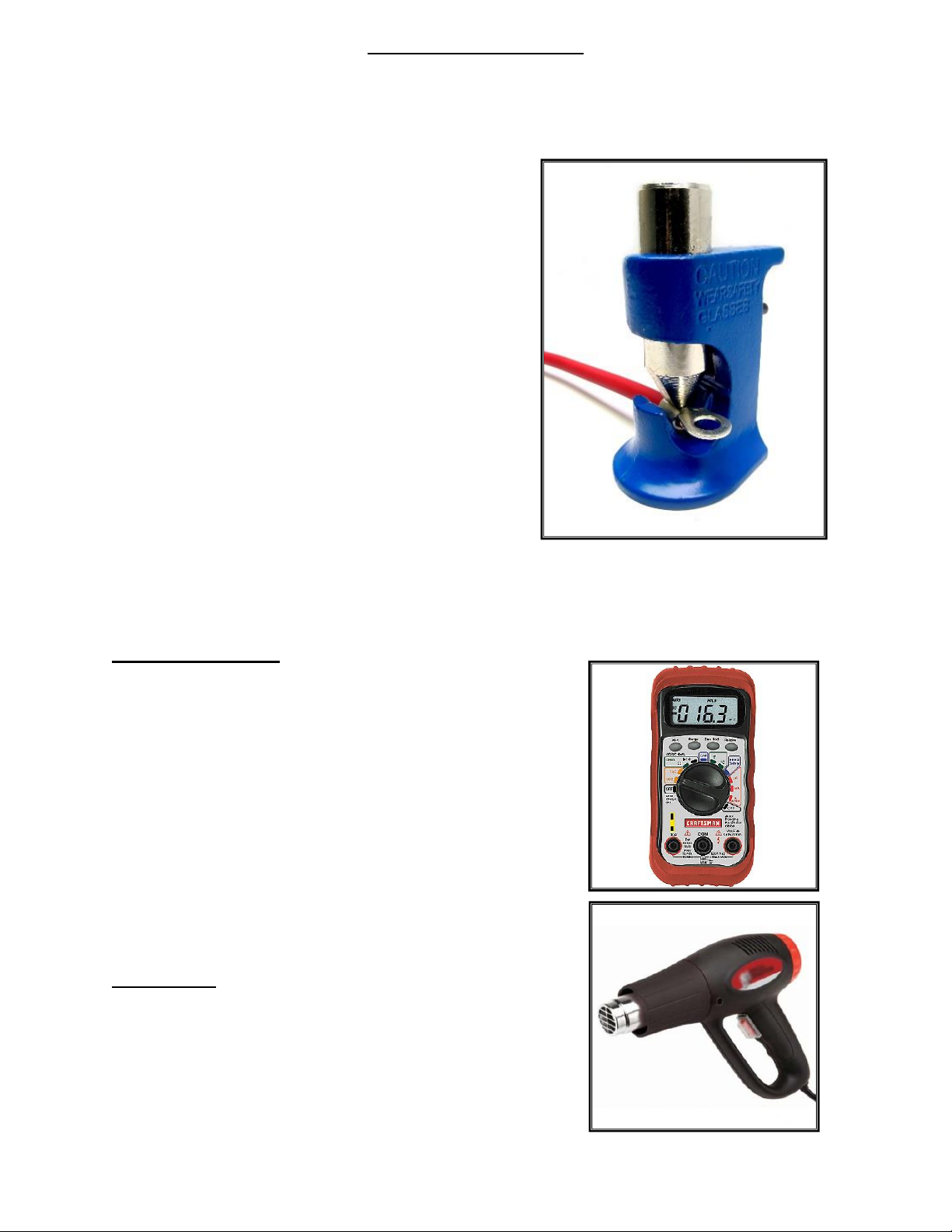
fuses, screws, and nuts. Many of the terminals are non-insulated and will require heat shrink to
be applied after the terminal has been properly crimped. Heat shrink has been supplied. These
non-insulated terminals allow you to keep a cleaner, more traditional look. When crimping these
terminals, take notice to the split in the terminal. Make sure the smooth side of the jaw on the
crimper goes towards this split.

2
TOOLS NEEDED
This installation primarily requires only basic hand tools that may
include, but are not limited to:
1. Wrench sets SAE and Metric
2. Ratchet sets SAE and Metric
a. ¼” Drive w/ an extension is recommended
for some tight areas of the install.
b. T30 Torx driver
3. Screwdrivers:
a. (2) #2 Standard Length and Stubby Phillips
Head
b. #2 Flat (slot) Head
c. #0 “Jewelers” Flat (slot) Head
4. Inch/Pound Torque Wrench
5. Diagonal Pliers or “dikes”
6. Wire Cutter/ 18-10 ga. Stripper
7. Hand Crimpers
8. Cable Cutters
9. Cable Crimping Tool
10. Hammer
In addition to these basic hand tools,
you may need the following:
Volt/Ohm Meter:
A Volt/Ohm meter is always a good tool to
have on hand when installing any type of
electrical component into a vehicle. The most
basic meters provide the two functions required
to diagnose electrical issues commonly seen
during a harness install. These two functions are
the ability to read DC Voltage and electrical
continuity or Ohms. They can be purchased
from any home improvement store, local
hardware store and electrical supply shop and
online.
Heat Gun:
Very useful to shrink the heat-shrink found in the
parts kit.

3
FUSE/RELAY CENTER INSTALLATION
The following steps MUST be followed as they are printed. Do not move
onto other parts of the installation out of sequence.
CAUTION: BEFORE THE INSTALLATION OF THIS PRODUCT,
DISCONNECT THE POWER FROM YOUR VEHICLE BY REMOVING THE
BATTERY CABLES FROM THE BATTERY. THE BATTERY SHOULD NOT TO
BE RECONNECTED UNTIL INSTRUCTED
Step 1: Use a 10mm wrench or socket to loosen and remove the
battery cables from the battery. For ease of installation, we also
recommend removing factory engine cover.

4
Step 2: Use a flathead screwdriver to lightly pry the factory wiring and
connector from the right side of the battery box. Then remove
the black plastic retainers, so that the connector is easy to stow
away later.

5
Step 3: After you remove the connector, “unlock” the red tab by using
a flathead screwdriver.

6
Step 4: With the tab unlocked unplug the connector.
Step 5: Use a 10mm wrench or socket to remove the battery tray
mounting nut from the stud on the firewall.

7
Step 6: Locate the Fuse/Relay Center in your new. Remove and
discard the black plastic retainers and flat washers securing the
Fuse/Relay Center to its packaging. The retainers and washers
are NOT used in installation.

8
Step 7: Remove the Fuse/Relay Center from the bracket. To do this
remove the lid from the Fuse/Relay Center using a 7∕16” wrench or
socket.
Step 8: Once the cover is removed, notice the mounting bolts located
below the relays.

9
Step 9: Use a #2 Stubby Philips-head screwdriver to hold the bolts in
place while you remove the ¼” threaded, acorns nuts on the
bottom of the unit with a 7∕16” wrench or socket.

10
Step 10:With the Fuse/Relay Center removed locate the center hole
on the bracket and a ¼”-20 stainless bolt. Insert the bolt into the
center hole.

11
Step 11:Fasten the bracket to the Fuse/Relay Center using the ¼”
threaded, acorns nuts you removed in Step 7.

12
Step 12: Position the Fuse/Relay Center mounting bracket over the
factory firewall mounted stud, and hand-tighten the factory
battery tray nut onto the firewall stud.

13
Step 13: Use the provided (1) ¼”-20 bolts, (1) flat washers, and (1)
nylon locking nuts to mount the Fuse/Relay Center mounting
bracket to the factory battery tray as shown.

14
Step 14: Use a 10mm wrench or socket to reinstall the factory battery
tray nut to stud on the firewall, and secure the Fuse/Relay Center
mounting bracket.

15
Step 15: Position (2) 1” Adel clamp over the Fuse/Relay Center control
wires.
Step 16: Mount the Adel clamps to the holes on the Fuse/Relay Center
bracket using the supplied (2) ¼”-20 bolts, (2) flat washers, and
(2) ¼” nylon locking nuts.

16
Step 17: Route the Fuse/Relay Center control wires across the
firewall. Secure the control wires to the factory harness loom
using the provided zip-ties. Remember, also, to reconnect the
factory connector you unplugged in Steps 2-4.
Step 18: On the driver side of the engine bay, locate the horn and
remove it using a 10mm wrench or socket.
Other manuals for Trail Rocker
1
This manual suits for next models
1
Table of contents
Other Painless Automobile Accessories manuals