manuals.online logo
Brands
  1. Home
  2. •
  3. Brands
  4. •
  5. PairGain
  6. •
  7. Network Hardware
  8. •
  9. PairGain PG-Flex FSU-796 User manual

PairGain PG-Flex FSU-796 User manual

FSU 796
CU STREAKER
PairGain
LIST 5
-170
VDC
-30
VDC
R1
R2
R3
R4
R5
R6
R7
R8
T1
T2
T3
T4
T5
T6
T7
T8
+5
VDC
200
VAC
-52
VDC
-5
VDC
TEST
Tip 1-8
LEDs Ring 1-8
LEDs
LED test switch
Line unit
power supply
voltages
PG-FLEX REMOTE TERMINAL
CHANNEL UNIT STREAKER CARD
QUICK REFERENCE GUIDE
This PairGain®PG-Flex™ FSU-796 List 5 Remote Terminal Channel Unit (RTCU) Streaker card is a continuity
tester. The card verifies that the Tip and Ring connections from the channel unit slots of a PG-Flex RT enclosure
are wired to the termination point correctly, and that the RT line unit is providing the required power supply
voltages to the channel units.
When you receive the PG-Flex FSU-796 List 5 Streaker card:
1Unpack the PG-Flex FSU-796 Streaker card and visually inspect it for signs of
damage. If the components have been damaged in transit, immediately report the
extent of damage to the transportation company and to your sales representative.
Order a replacement unit if necessary.
2Compare the contents of the package against the packing list. If the shipment is
incorrect, contact PairGain as described in the "Limited Warranty" section.
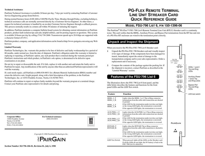
The illustration shows the FSU-796 List 5 front panel, and the table describes
the features and functions for the front panel LEDs and the LED Test switch.
MODEL FSU-796 LIST 5, P/N150-1396-05
Feature Function
Tip 1 - 8
LEDs
(T1 - T8)
Lights when one of the Tip subscriber terminations
(T1 - T8) is shorted to ground.
If the LED for the termination under test does not light,
the termination is miswired.
If the corresponding Ring LED lights, the subscriber
termination is reversed.
Ring 1 - 8
LEDs
(R1 - R8)
Lights when one of the Ring subscriber terminations
(R1 - R8) is shorted to ground.
If the LED for the termination under test does not light,
the termination is miswired.
If the corresponding Tip LED lights, the subscriber
termination is reversed.
Line Unit Power Supply Voltages
-170 Vdc
200 Vac
-30 Vdc
-52 Vdc
±5 Vdc
The six power supply LEDs indicate that the RT line unit
is installed in the RT enclosure and is supplying power
supply voltages to the channel unit.
If any one of the LEDs do not light, the RT line unit is
defective.
LED Test
switch When pressed, lights all the LEDs on the Streaker card.
If all LEDs do not light, the 9V battery is bad or the
FSU-796 List 5 is defective.
Unpack and Inspect the Shipment
Features of the FSU-796 List 5
Technical Assistance
PairGain Technical Assistance is available 24 hours per day, 7 days per week by contacting PairGain’s Customer
Service Engineering group (listed below).
During normal business hours (8:00 AM to 5:00 PM, Pacific Time, Monday through Friday, excluding holidays),
technical assistance calls are normally answered directly by a Customer Service Engineer. At other times, a
request for technical assistance is handled by an on-duty Customer Service Engineer through a callback process.
This process normally results in a return call within 30 minutes of initiating the request.
In addition, PairGain maintains a computer bulletin board system for obtaining current information on PairGain
products, product fault isolation tips and aids, helpful utilities, and for posting requests or questions. This system
is available 24 hours per day by calling (714) 730-2800. Transmission speeds up to 28.8 kbps are supported with
a character format of 8-N-1.
PairGain product, company, and application information can be found at http://www.pairgain.com using any Web
browser.
Limited Warranty
PairGain Technologies, Inc. warrants this product to be free of defective and faulty workmanship for a period of
60 months, under normal use, from the date of shipment. PairGain's obligation under this warranty is limited to
replacing or repairing, at PairGain's option, any such product that is returned during the warranty period per
PairGain's instructions and which product, in PairGain's sole option, is determined to be defective upon
examination at our plant.
Do not try to repair or disassemble the unit. If it fails, replace it with another unit and return the faulty unit to
PairGain for repair. Any modifications of the unit by anyone other than an authorized PairGain representative will
void the warranty.
If a unit needs repair, call PairGain at (800) 638-0031 for a Return Material Authorization (RMA) number and
return the defective unit, freight prepaid, along with a brief description of the problem, to the PairGain
Technologies, Inc. at 14352 Franklin Avenue, Tustin, CA 92780-7013.
PairGain will continue to repair or replace faulty modules beyond the warranty program at a nominal charge.
Contact your PairGain sales representative for details and pricing.
Corporate Office: ForTechnicalAssistance:
14402 Franklin Avenue (800) 638-0031
Tustin, CA 92780
Tel: (714) 832-9922
FAX: (714) 832-9924
Copyright © 1998 PairGain Technologies Inc.
Section Number 363-796-105-01, Revision 01, July 6, 1998
1Press the LED Test switch on the FSU-796 List 5 front panel and verify that all Tip and Ring LEDs
(T1-T8 and R1-R8) and power supply LEDs (-170 Vdc, 200 Vac, -30 Vdc, -52 Vdc, and ±5 Vdc)
are on.
• If no LEDs light, replace the 9V battery.
• If no LEDs light after replacing the 9V battery, replace the FSU-796 List 5 Streaker card.
• If any one of the LEDs do not light, replace the FSU-796 List 5 Streaker card.
1Slide the FSU-796 List 5 into the RT enclosure channel unit slot to be tested until the retaining latch on the
front panel locks into position. (Refer to Figure 1 for the channel unit locations.)
2Proceed to "Verifying the Channel Unit Slot Wiring."
Use the following procedure to verify the wiring from each channel unit slot in an FRE-765 RT enclosure to the
termination point.
1At the cable termination point, connect a jumper lead from frame ground to the appropriate Tip or Ring
subscriber termination and verify that the corresponding Tip or Ring LED on the FSU-796 List 5 is on.
• If the correct Tip or Ring LED lights, proceed to the next subscriber termination.
• If the Tip or Ring LED under test does not light, or the wrong LED lights, check the wiring to the RT
enclosure.
2Repeat the previous step for each channel card Tip and Ring subscriber termination.
3Proceed to "Testing the Line Unit Power Supply Voltages."
Verify that a 9V battery is installed on the FSU-796 List 5 Streaker card before starting this
procedure.
An RT line unit is not required when testing the channel unit slot wiring.
Refer to the appropriate FRE-765 RT enclosure technical practice for channel unit
subscriber terminations, and wire color or connector pin locations for the specific
FRE-765 RT enclosure to be tested.
Before You Install the FSU-796 List 5
Installing and Testing the FSU-796 List 5
Verifying the Channel Unit Slot Wiring
Use the following procedure to verify that the line unit power supply voltages are present at each of the channel
unit slots.
1Slide the FSU-796 List 5 into the RT enclosure channel unit slot to be tested until the retaining latch on the
front panel locks into position. (Refer to Figure 1 for the channel unit locations.)
2Verify that the -170 Vdc, 200 Vac, -30 Vdc, -52 Vdc, and ±5 Vdc LEDs are on.
• If any of the power supply LEDs do not light, replace the line unit.
• If none of the power supply LEDs light, check that power is applied.
3Repeat steps 1 and 2 for each channel unit slot.
.
Figure 1. Channel Unit Slots CU1 - CU4
(FRE-765 List 4D and 4E Shown)
An RT line unit must be installed and operating (with power applied) to supply the FSU-796
List 5 with the power supply voltages (-170 Vdc, 200 Vac, -30 Vdc, -52 Vdc, and ±5 Vdc)
required for this test.
Testing the Line Unit Power Supply Voltages
9
10
8
7
6
5
4
3
2
1
9
10
8
7
6
5
4
3
2
1
9
10
8
7
6
5
4
3
2
1
Channel unit slots
(CU1-CU4)

This manual suits for next models

1

Other PairGain Network Hardware manuals

PairGain HLU-319 User manual

PairGain

PairGain HLU-319 User manual

PairGain PG-FLEX RT FRL-776 User manual

PairGain

PairGain PG-FLEX RT FRL-776 User manual

PairGain HLU-319 User manual

PairGain

PairGain HLU-319 User manual

PairGain HLU-319 User manual

PairGain

PairGain HLU-319 User manual

PairGain T1L2F10A User manual

PairGain

PairGain T1L2F10A User manual

PairGain T1L2B40A User manual

PairGain

PairGain T1L2B40A User manual

PairGain 150-1140-51 User manual

PairGain

PairGain 150-1140-51 User manual

PairGain PG-Flex FRC-751 User manual

PairGain

PairGain PG-Flex FRC-751 User manual

PairGain T1L2BZ0A User manual

PairGain

PairGain T1L2BZ0A User manual

PairGain HiGain Line Unit HLU-388 User manual

PairGain

PairGain HiGain Line Unit HLU-388 User manual

PairGain HLU-431 User manual

PairGain

PairGain HLU-431 User manual

PairGain HLU-431 User manual

PairGain

PairGain HLU-431 User manual

PairGain PG-Flex FRC-754 L4 User manual

PairGain

PairGain PG-Flex FRC-754 L4 User manual

PairGain PG-Flex FLC-704 User manual

PairGain

PairGain PG-Flex FLC-704 User manual

PairGain PG-Flex 8 FLC-704 User manual

PairGain

PairGain PG-Flex 8 FLC-704 User manual

PairGain FLC-703 User manual

PairGain

PairGain FLC-703 User manual

PairGain HLU-231 User manual

PairGain

PairGain HLU-231 User manual

PairGain HLU-319 User manual

PairGain

PairGain HLU-319 User manual

PairGain T1L2PY0AA User manual

PairGain

PairGain T1L2PY0AA User manual

PairGain HLU-319 User manual

PairGain

PairGain HLU-319 User manual

PairGain HIGAIN HLU-232 User manual

PairGain

PairGain HIGAIN HLU-232 User manual

PairGain PG-Flex FRC-753 List 4C Instructions for use

PairGain

PairGain PG-Flex FRC-753 List 4C Instructions for use

PairGain HiGain HDU-451 User manual

PairGain

PairGain HiGain HDU-451 User manual

PairGain HiGain ELU-819 User manual

PairGain

PairGain HiGain ELU-819 User manual

Popular Network Hardware manuals by other brands

Checkpoint 21000 Appliances G-70 Mounting

Checkpoint

Checkpoint 21000 Appliances G-70 Mounting

Black Box SW549A Specifications

Black Box

Black Box SW549A Specifications

HIK VISION DS-7732NI-I4/16P quick start guide

HIK VISION

HIK VISION DS-7732NI-I4/16P quick start guide

Alpha Shield INTERNET PRIVACY PROTECTION Manual Del Usuario

Alpha Shield

Alpha Shield INTERNET PRIVACY PROTECTION Manual Del Usuario

TV One 1RK-SPDR-STRIP-23 user guide

TV One

TV One 1RK-SPDR-STRIP-23 user guide

Itec ITECNET SPIDER 44/02 manual

Itec

Itec ITECNET SPIDER 44/02 manual

Black Box 39625 Specifications

Black Box

Black Box 39625 Specifications

HIK VISION DS-7608NI-I2/8P user manual

HIK VISION

HIK VISION DS-7608NI-I2/8P user manual

High Sec Labs FICE11PH-M Quick setup guide

High Sec Labs

High Sec Labs FICE11PH-M Quick setup guide

HIK VISION HiLook IK-6288TH-MH/P user manual

HIK VISION

HIK VISION HiLook IK-6288TH-MH/P user manual

HIK VISION DeepinMind iDS-6700NXI-I/8F(B) Series user manual

HIK VISION

HIK VISION DeepinMind iDS-6700NXI-I/8F(B) Series user manual

CoolAutomation CLOUDBOX Quick installation guide

CoolAutomation

CoolAutomation CLOUDBOX Quick installation guide

REV eero Getting started

REV

REV eero Getting started

Tripp Lite N48M Series installation guide

Tripp Lite

Tripp Lite N48M Series installation guide

HIK VISION DS-7604NI-VP user manual

HIK VISION

HIK VISION DS-7604NI-VP user manual

Baicells Nova230i installation guide

Baicells

Baicells Nova230i installation guide

HIK VISION DS-7100NI-Q1 Series quick start guide

HIK VISION

HIK VISION DS-7100NI-Q1 Series quick start guide

AVPro Edge AC-MXNET-10G-CBOX quick start guide

AVPro Edge

AVPro Edge AC-MXNET-10G-CBOX quick start guide

manuals.online logo
manuals.online logoBrands
  • About & Mission
  • Contact us
  • Privacy Policy
  • Terms and Conditions

Copyright 2025 Manuals.Online. All Rights Reserved.