manuals.online logo
Brands
  1. Home
  2. •
  3. Brands
  4. •
  5. PairGain
  6. •
  7. Network Hardware
  8. •
  9. PairGain PG-Flex FSU-796 User manual

PairGain PG-Flex FSU-796 User manual

FSU 796
LU STREAKER
PairGain
LIST 6
R
R
R
R
R
HDSL 1
HDSL 2
AUX PWR 1
AUX PWR 2
BYPASS
T
T
T
T
T
TEST
HDSL 1 and 2
Tip and Ring
LEDs
Auxiliary Power
1 and 2 Tip
and Ring LEDs
Bypass Pair
Tip and Ring
LEDs
LED test switch
PG-FLEX REMOTE TERMINAL
LINE UNIT STREAKER CARD
QUICK REFERENCE GUIDE
The PairGain®PG-Flex™ FSU-796 List 6 Remote Terminal Line Unit (RTLU) Streaker card is a continuity
tester. The card verifiesthat the HDSL, Auxiliary Power, and Bypass Pair terminations from the RT line unit slot
of a PG-Flex RT enclosure are wired to the termination point correctly.
When you receive the PG-Flex FSU-796 List 6 Streaker card:
1Unpack the PG-Flex FSU-796 Streaker card and visually inspect
it for signs of damage. If the components have been damaged in
transit, immediately report the extent of damage to the
transportation company and to your sales representative. Order a
replacement unit if necessary.
2Compare the contents of the package against the packing list. If
the shipment is incorrect, contact PairGain as described in the
"Limited Warranty" section.
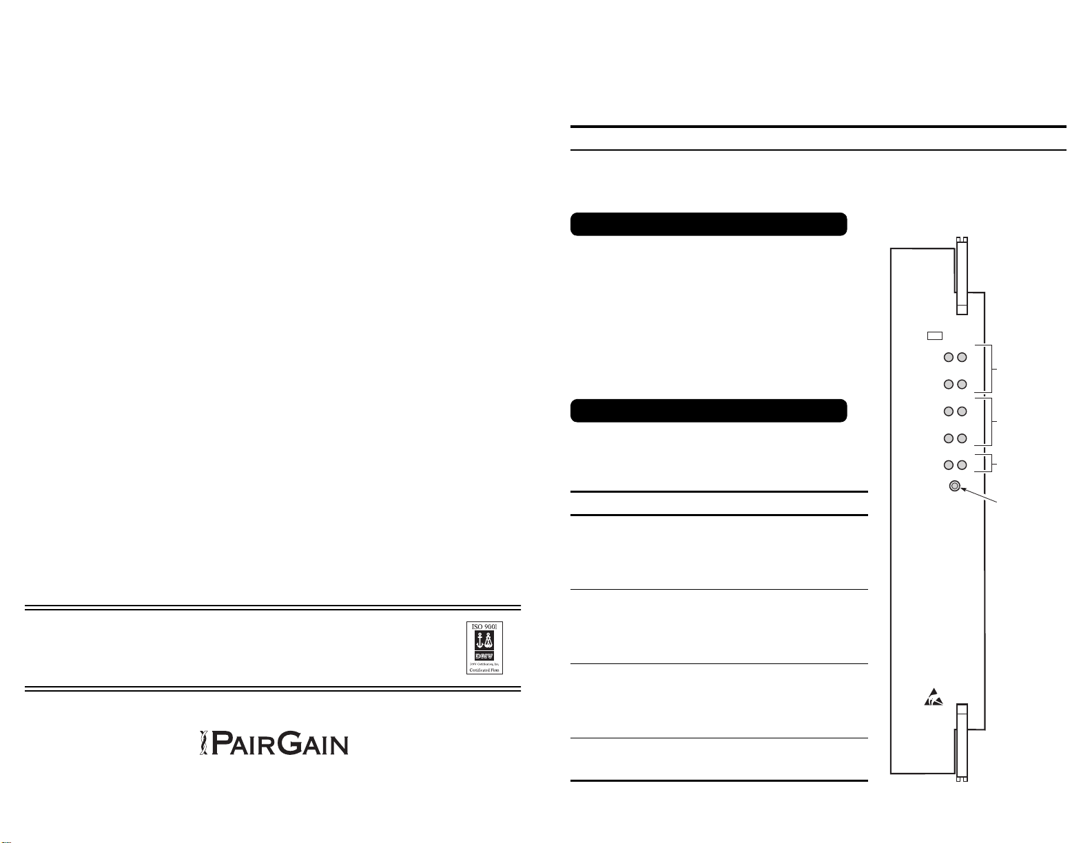
The illustration shows the FSU-796 List 6 front panel, and the
table below describes the features and functions for the front
panel LEDs and the LED Test switch.
MODEL FSU-796 LIST 6, P/N150-1396-06
Feature Function
HDSL_1_T
HDSL_1_R
HDSL_2_T
HDSL_2_R
Lights when the HDSL 1 or 2 Tip or Ring connector
terminations from the cable stub connections are shorted
to ground.
If the LED for the termination under test does not light,
or the wrong LED lights, the termination is miswired.
If the opposite LED lights, the termination is reversed.
AUX PWR_1_T
AUX PWR_1_R
AUX PWR_2_T
AUX PWR_2_R
Lights when the AUX PWR 1 or 2Tip or Ring connector
terminations from the cable stub connections are shorted
to ground.
If the LED for the termination under test does not light,
or the wrong LED lights, the termination is miswired.
If the opposite LED lights, the termination is reversed.
BYPASS_T
BYPASS_R Lights when the BYPASS Tip or Ring connector
termination from the cable stub connection is shorted to
ground.
If the LED for the termination under test does not light,
or the wrong LED lights, the termination is miswired.
If the opposite LED lights, the termination is reversed.
LED Test Switch When pressed, lights all the LEDs on the Streaker card.
If all the LEDs do not light, the 9V battery is bad or the
FSU-796 List 6 is defective.
Unpack and Inspect the Shipment
Features of the FSU-796 List 6
Technical Assistance
PairGain Technical Assistance isavailable 24 hours per day, 7 daysper week by contacting PairGain’s Customer
Service Engineering group (listed below).
During normal business hours (8:00 AM to 5:00 PM, Pacific Time, Monday through Friday, excluding holidays),
technical assistance calls are normally answered directly by a Customer Service Engineer. At other times, a
request for technical assistance is handled by an on-duty Customer Service Engineer through a callback process.
This process normally results in a return call within 30 minutes of initiating the request.
In addition, PairGain maintains a computer bulletin board system for obtaining current information on PairGain
products, product fault isolation tips and aids, helpful utilities, and for posting requests or questions. This system
is available 24 hours per day by calling (714) 730-2800. Transmission speeds up to 28.8 kbps are supported with
a character format of 8-N-1.
PairGain product, company, and application information can be found at http://www.pairgain.com using any Web
browser.
Limited Warranty
PairGain Technologies, Inc. warrants this product to be free of defective and faulty workmanship for a period of
60 months, under normal use, from the date of shipment. PairGain's obligation under this warranty is limited to
replacing or repairing, at PairGain's option, any such product that is returned during the warranty period per
PairGain's instructions and which product, in PairGain's sole option, is determined to be defective upon
examination at our plant.
Do not try to repair or disassemble the unit. If it fails, replace it with another unit and return the faulty unit to
PairGain for repair. Any modifications of the unit by anyone other than an authorized PairGain representative will
void the warranty.
If a unit needs repair, call PairGain at (800) 638-0031 for a Return Material Authorization (RMA) number and
return the defective unit, freight prepaid, along with a brief description of the problem, to the PairGain
Technologies, Inc. at 14352 Franklin Avenue, Tustin, CA 92780-7013.
PairGain will continue to repair or replace faulty modules beyond the warranty program at a nominal charge.
Contact your PairGain sales representative for details and pricing.
Corporate Office: ForTechnicalAssistance:
14402 Franklin Avenue (800) 638-0031
Tustin, CA 92780
Tel: (714) 832-9922
FAX: (714) 832-9924
Copyright © 1998 PairGain Technologies Inc.
Section Number 363-796-106-01, Revision 01, July 6, 1998
Press the LED Test switch on the front panel of the FSU-796 List 6 and verify that all LEDs are on.
• If no LEDs light, replace the 9V battery.
• If no LEDs light after replacing the 9V battery, replace the FSU-796 List 6 Streaker card.
• If any one of the LEDs do not light, replace the FSU-796 List 6 Streaker card.
1Slide the FSU-796 List 6 into the RT enclosure line-unit slot until the retaining latch on the front panel
locks into position. (Refer to Figure 1 for the line unit slot location.)
2Proceed to “Verifying the Line Unit Slot Wiring” on the next page.
.
Figure 1. Line Unit Slot Location
(FRE-765 Lists 4D and 4E Shown)
Verify that a 9V battery is installed on the FSU-796 List 6 Streaker card before starting this
procedure.
Before You Install the FSU-796 List 6
Installing the FSU-796 List 6
9
10
8
7
6
5
4
3
2
1
9
10
8
7
6
5
4
3
2
1
9
10
8
7
6
5
4
3
2
1
Line unit slot
Use the following procedure to verify the wiring between an FRE-756 RT enclosure and the termination point.
1At the cable stub termination, connect a jumper lead from frame ground to the appropriate termination from
the RT enclosure. Verify that the corresponding LED on the FSU-796 is on. (Refer to Table 1 for the HDSL,
Auxiliary Power, and Bypass Pair wire pair colors for the Lists 4D and 4E.)
• If the correct LED lights, proceed to the next connector termination.
• If the LED under test does not light, check that the wiring to the RT enclosure.
• If the opposite or wrong LED lights, check for reversed wiring.
2Repeat the previous step for each line unit termination.
Power should not be applied to the FRE-765 RT enclosure while verifying the wiring.
Table 1. HDSL, Auxiliary Power, and Bypass Line Unit Terminations
Connector 6 Pair Cable Stub Function
HDSL_1_T
HDSL_1_R WH
BL Tip and Ring terminations for HDSL Pair #1. -130 Vdc is
simplexed on this line for powering the Remote Terminal.
HDSL_2_T
HDSL_2_R WH
OR Tip and Ring terminations for HDSL Pair #2. +130 Vdc is
simplexed on this line for powering the Remote Terminal.
AUX_PWR_1_T
AUX_PWR_1_R WH
BN Auxiliary Power Pair #1. Used for auxiliary power to the RT
when using a PG-Flex doubler unit.
AUX_PWR_2_T
AUX_PWR_2_R WH
SL Auxiliary Power Pair #2. Used for auxiliary power to the RT
when using a PG-Flex doubler unit.
BYPASS_T
BYPASS_R WH
GN Termination for the metallic bypass pair from the COT to the
RT.
(Spare) RD
BL No connection—reserved for future use.
Verifying the Line Unit Slot Wiring

This manual suits for next models

1

Other PairGain Network Hardware manuals

PairGain HiGain ELU-819 User manual

PairGain

PairGain HiGain ELU-819 User manual

PairGain HiGain Line Unit HLU-388 User manual

PairGain

PairGain HiGain Line Unit HLU-388 User manual

PairGain HiGain HDU-451 User manual

PairGain

PairGain HiGain HDU-451 User manual

PairGain PG-Flex FRC-753 List 4C Instructions for use

PairGain

PairGain PG-Flex FRC-753 List 4C Instructions for use

PairGain HiGain-ETSI RS UTU 712 User manual

PairGain

PairGain HiGain-ETSI RS UTU 712 User manual

PairGain HIGAIN HLU-232 User manual

PairGain

PairGain HIGAIN HLU-232 User manual

PairGain HiGain HLU-819 User manual

PairGain

PairGain HiGain HLU-819 User manual

PairGain PF-FLEX FLC-704 User manual

PairGain

PairGain PF-FLEX FLC-704 User manual

PairGain HLU-431 User manual

PairGain

PairGain HLU-431 User manual

PairGain HiGain HDU-451 User manual

PairGain

PairGain HiGain HDU-451 User manual

PairGain HLU-319 User manual

PairGain

PairGain HLU-319 User manual

PairGain HiGain Line Unit HLU-388 User manual

PairGain

PairGain HiGain Line Unit HLU-388 User manual

PairGain PG-PLUS PLL-734 User manual

PairGain

PairGain PG-PLUS PLL-734 User manual

PairGain PG-FLEX FRL-746 List 1 User manual

PairGain

PairGain PG-FLEX FRL-746 List 1 User manual

PairGain HiGain SOLITAIRE H2TU-C-319 List 1 Instructions for use

PairGain

PairGain HiGain SOLITAIRE H2TU-C-319 List 1 Instructions for use

PairGain PG-FLEX RT FRL-776 User manual

PairGain

PairGain PG-FLEX RT FRL-776 User manual

PairGain T1L2PY0AA User manual

PairGain

PairGain T1L2PY0AA User manual

PairGain HLU-231 User manual

PairGain

PairGain HLU-231 User manual

PairGain HLU-319 User manual

PairGain

PairGain HLU-319 User manual

PairGain T1L2BZ0A User manual

PairGain

PairGain T1L2BZ0A User manual

PairGain T1L2F10A User manual

PairGain

PairGain T1L2F10A User manual

PairGain PG-Flex FRC-754 L4 User manual

PairGain

PairGain PG-Flex FRC-754 L4 User manual

PairGain HIGAIN HRU-412 User manual

PairGain

PairGain HIGAIN HRU-412 User manual

PairGain T1L2N20A User manual

PairGain

PairGain T1L2N20A User manual

Popular Network Hardware manuals by other brands

TeleEye RX806 User guide lite

TeleEye

TeleEye RX806 User guide lite

ADC UltraWAVE 2000 Brochure & specs

ADC

ADC UltraWAVE 2000 Brochure & specs

Siemens SANTIS-ab user manual

Siemens

Siemens SANTIS-ab user manual

EFI Fiery proServer installation guide

EFI

EFI Fiery proServer installation guide

Visionman VCM400 user manual

Visionman

Visionman VCM400 user manual

ZyXEL Communications Network Device P-2602 user guide

ZyXEL Communications

ZyXEL Communications Network Device P-2602 user guide

Cabletron Systems WPIM-SY Management guide

Cabletron Systems

Cabletron Systems WPIM-SY Management guide

Aperto PacketWave 1000 Series Installation, configuration, and operation manual

Aperto

Aperto PacketWave 1000 Series Installation, configuration, and operation manual

Lenovo Iomega ix2 quick start guide

Lenovo

Lenovo Iomega ix2 quick start guide

Ubiquiti USW-24 quick start guide

Ubiquiti

Ubiquiti USW-24 quick start guide

Symantec RP-S500 quick start guide

Symantec

Symantec RP-S500 quick start guide

Telebyte 458-3SLB manual

Telebyte

Telebyte 458-3SLB manual

Direct IP IDIS DR-2300P Series quick guide

Direct IP

Direct IP IDIS DR-2300P Series quick guide

ADC PG-PLUS PLL-720 Technical practice

ADC

ADC PG-PLUS PLL-720 Technical practice

ZKTeco VSR0402 user manual

ZKTeco

ZKTeco VSR0402 user manual

Huawei FTK01 Quick installation guide

Huawei

Huawei FTK01 Quick installation guide

Cleco LiveWire 943620PT instruction manual

Cleco

Cleco LiveWire 943620PT instruction manual

Allnet ALL95102O Quick installation guide

Allnet

Allnet ALL95102O Quick installation guide

manuals.online logo
manuals.online logoBrands
  • About & Mission
  • Contact us
  • Privacy Policy
  • Terms and Conditions

Copyright 2025 Manuals.Online. All Rights Reserved.