PairGain FLC-703 User manual

PG-FLEX EIGHT CHANNEL
CENTRAL OFFICE TERMINAL
LOOP START/GROUND START UNIT
Model List Number Part Number CLEI Code
FLC-703 4 150-1303-04 VACHCHGCAA
PAIRGAIN TECHNOLOGIES, INC.
ENGINEERING PLANT SERIES TECHNICAL PRACTICE
SECTION 363-703-104-01
Revision History of this practice.
Revision 01—June 5, 1997
A) Initial Release.

Section 363-703-104 June 5, 1997 Revision 01
ii PairGain Engineering - Plant Series PG-Flex FLC-703
TABLE OF CONTENTS
A. PRODUCT OVERVIEW................................................................................................................1
1. Description and Features....................................................................................................1
2. Front Panel........................................................................................................................2
3. Specifications....................................................................................................................3
B. FUNCTIONAL DESCRIPTION......................................................................................................4
4. Applications ......................................................................................................................4
5. Operational Capabilities ....................................................................................................4
C. INSTALLATION AND TEST.........................................................................................................6
6. Unpacking.........................................................................................................................6
7. Installation.........................................................................................................................6
8. Troubleshooting.................................................................................................................7
D. TECHNICAL SUPPORT.................................................................................................................9
9. Technical Support..............................................................................................................9
E. CERTIFICATION AND WARRANTY..........................................................................................9
10. Certification.....................................................................................................................9
11. Warranty.........................................................................................................................10
F. ABBREVIATIONS.........................................................................................................................11
12. Abbreviations .................................................................................................................11
USING THIS TECHNICAL PRACTICE
Three types of messages, identified by icons, appear in the text:
A note informs you of special circumstances.
A caution indicates the possibility of equipment damage.
A warning indicates the possibility of personal injury.
Copyright © 1997, PairGain Technologies, Inc.
PairGain is a registered trademark, and PG-Flex is a trademark of PairGain Technologies, Inc.

Revision 01 June 5, 1997 Section 363-703-104
PG-Flex FLC-703 PairGain Engineering - Plant Series Page 1
A. PRODUCT OVERVIEW
1. Description and Features
1.1 The PairGain
®
PG-Flex FLC-703 List 4 Channel Unit provides eight loop start or ground start
channel interfaces for Plain Old Telephone Service (POTS) between a PG-Flex Central Office
Terminal (COT) and the Central Office (CO) switch. You can provision each of the eight circuits
separately for either loop start or ground start services. Provisioning is done through the PG-Flex
Line Unit Maintenance port.
The FLC-703 unit provides metallic test access to the subscriber line connection through an optional
metallic bypass pair. Perform metallic bypass testing either manually or through the Pair Gain Test
Controller (PGTC).
1.2 Features of the FLC-703 COT Channel Unit are:
•eight loop start or ground start POTS subscriber interfaces
•64 kbps µ-Law Pulse Code Modulation (PCM) encoding
•front panel ACTIVE LEDs
•front panel FAULT LED
•PGTC compatibility
•Custom Local Area Signaling Services (CLASS) support (i.e., caller ID)
•line-side answer supervision support (reverse battery)
•forward disconnect
•distinctive ringing
•connection for a subscriber loop to a metallic bypass test pair
•repeat of loop off-hook, ground start seizure, and Ring-Tip conditions to the CO switch

Section 363-703-104 June 5, 1997 Revision 01
Page 2 PairGain Engineering - Plant Series PG-Flex FLC-703
2. Front Panel
2.1 Figure 1 shows the FLC-703 front panel. Table 1 lists the different states and indications for the
FLC-703 Channel Unit front panel LEDs.
Figure 1. FLC-703 Front Panel
Table 1. FLC-703 Front Panel LEDs
LED LED State Indicates
Solid green Channel is off hook.
ACTIVE Fast flashing green Channel is in test.
(1 through 8) Slow flashing green Channel is ringing.
Off Channel is on hook.
FAULT Red Fault detected by the unit.
Off No faults detected.

Revision 01 June 5, 1997 Section 363-703-104
PG-Flex FLC-703 PairGain Engineering - Plant Series Page 3
3. Specifications
Electrical Characteristics
Analog Impedance ......................................900 Ω
Loop Length ...............................................100 ft (CO switch to COT)
End-to-End Loss .........................................-2.5 dB ±1.0
Ring-Ground Resistance..............................500 Ω
Channel Signature.......................................Loop Start Lines Ground Start Lines
Tip-Ring...............................................(open) 23.75 kΩ, 1%
Tip-Ground ..........................................162 kΩ, 1% 162 kΩ, 1%
Ring-Ground ........................................226 kΩ, 1% 226 kΩ, 1%
Environmental
Operating Elevation ....................................-200 ft. to 13,000 ft
(-60 m to 4,000 m)
Temperature and Humidity .........................-40° F to +150° F (-40° C to +65° C)
5% to 95% (non condensing)
Physical
Weight ........................................................0.8 lb (0.4 kg)
Dimensions
Height..................................................6.75 in. (17.2 cm)
Width...................................................1.00 in. (2.5 cm)
Depth...................................................10.50 in. (26.7 cm)

Section 363-703-104 June 5, 1997 Revision 01
Page 4 PairGain Engineering - Plant Series PG-Flex FLC-703
B. FUNCTIONAL DESCRIPTION
4. Applications
4.1 The FLC-703 provides service to one of the following configurations:
•eight independent loop start subscriber lines or
•eight ground start Private Branch Exchange (PBX) lines or
•a mixture of both loop start subscriber lines and ground start PBX lines
Figure 2 shows a typical system with loop start and ground start services.
Figure 2. Typical System with Loop Start and Ground Start Capabilities
5. Operational Capabilities
5.1 FLC-703 Functions. The FLC-703 Channel Unit provides eight POTS channel interfaces to the
CO switch. Each FLC-703 detects:
•forward battery
•ringing voltage
•reverse battery
•Tip ground
5.2 Circuit Operation. The following paragraphs define the FLC-703 circuit operation when using
loop start for subscriber lines or ground start for PBX lines. Each FLC-703 circuit has an associated
LED that indicates when the line is off-hook, idle, ringing, or under test. See Table 1.

Revision 01 June 5, 1997 Section 363-703-104
PG-Flex FLC-703 PairGain Engineering - Plant Series Page 5
5.2.1 Loop start idle condition is a Ring lead negative and Tip lead positive from the Central Office
Terminal (COT) with the same conditions out of the RT toward the subscriber. The following occurs
when the calling line goes off-hook:
loop current flows and is detected by the FRC-753
FLC-703 receives an off-hook signal from the RT
FLC-703 generates an off-hook signal to the Central Office (CO) to begin current flow
CO sends dial tone
FRC-753 recognizes dial pulses or Dual Tone Multi Frequency (DTMF) signaling, from the
subscriber and forwards these as loop current breaks, dialing or DTMF signaling, at the CO
The following occurs for an incoming call:
FLC-703 detects a ringing signal from the CO
FLC-703 signals the FRC-753 which then connects ringing to the subscriber
subscriber line goes off-hook and the FRC-753, via the FLC-703, signals the CO to disconnect
ringing and establish an audio path
5.2.2 Ground start idle condition is a Tip lead open and Ring lead negative into the CO and Tip lead open
and Ring lead negative at the RT. The following occurs when a PBX requests service for an
outgoing call by grounding the Ring lead at the RT:
FRC-753 signals the FLC-703
FLC-703 operates a Ring ground relay that requests dial tone from the CO (this makes the
circuit busy, or seizes it, for outgoing calls to prevent others from using it, i.e., prevents glare
where different users can seize a line at the same time)
CO sends dial tone and grounds the Tip to signal the PBX to begin dialing
FLC-703 detects Tip ground, closes the loop between Tip and Ring, and signals the FRC-753 to
send Tip ground to the PBX
PBX removes the original Ring ground condition and completes the loop (Tip and Ring)
The following occurs for an incoming call:
FLC-703 detects a ringing signal from the CO, along with Tip ground
FLC-703 signals the FRC-753 which then connects Tip ground and ringing to the PBX
PBX goes off-hook and the FRC-753, via the FLC-703, signals the CO to disconnect ringing and
establish an audio path
5.2.3 When caller ID (a CLASS feature) is activated, the CO generates a signal to the subscriber between
the first and second bursts of the ringing signal only (i.e., PG-Flex supports on-hook transmisssion).
The forward-disconnect function releases a called line that was left on hold or an answering set that
requires a loop open to be able to turn off.

Section 363-703-104 June 5, 1997 Revision 01
Page 6 PairGain Engineering - Plant Series PG-Flex FLC-703
C. INSTALLATION AND TEST
6. Unpacking
6.1 Upon receipt of the equipment, proceed as follows:
1Unpack each container and visually inspect it for signs of damage. If the equipment has been
damaged in transit, immediately report the extent of damage to the transportation company and
to PairGain. Order replacement equipment if necessary.
2Check the contents versus the packing list to ensure complete and accurate shipment. If the
shipment is short or irregular, contact PairGain as described in Section 11. If you must store the
equipment for a prolonged period, store the equipment in its original container.
7. Installation
Observe normal electrostatic discharge precautions when handling electronic
equipment. Do not hold electronic plug-ins by their edge. Do not touch
components or circuitry.
7.1 Install the FLC-703. Insert the FLC-703 into the shelf and observe that all LEDs:
•
turn ON for approximately 2 seconds
•
scan from top to bottom
•turn OFF
If the LEDs do not follow the above sequence, see Table 1.
Use List 3 or higher PG-Flex CO and RT Line Units when activating the ground
start feature.
7.2 Provision the FLC-703. Provision the FLC-703 using the FLL-712 List 3 CO Line Unit practice.
For each channel provisioned, select loop start or ground start.
7.3 Connect Cabling. Place a cross-connect (jumper) from the CO to the appropriate PairGain
COT shelf termination for the FLC-703 circuit(s) selected.

Revision 01 June 5, 1997 Section 363-703-104
PG-Flex FLC-703 PairGain Engineering - Plant Series Page 7
7.4 Verify Operation. Verify the following after the system is powered up and HDSL communication
is synchronized:
1Observe the front panel ACTIVE indicators are all OFF and the FAULT indicator is off (no calls
are in progress).
2Test circuits for loop start:
aPlace an outgoing call for each subscriber circuit provisioned and observe that the
appropriate ACTIVE LED tracks the progress of the call (Table 1).
bPlace an incoming call for each subscriber circuit provisioned and observe that the
appropriate ACTIVE LED tracks the progress of the call (Table 1).
3Test circuits for ground start (circuits must be provisioned for ground start per section 7.2):
aPlace an outgoing call for each subscriber circuit provisioned and observe that the
appropriate ACTIVE LED tracks the progress of the call (Table 1).
bPlace an incoming call for each subscriber circuit provisioned and observe that the
appropriate ACTIVE LED tracks the progress of the call (Table 1).
8. Troubleshooting
8.1 Subscriber Drop Testing. For PG-Flex subscriber drop testing from the CO, select and connect
any subscriber drop to a metallic test pair at the RT. PG-Flex extends this connection to the COT
where it can be switched onto the test access bus or to the corresponding subscriber line on the COT
channel card.
Activate test access through the RS-232 maintenance port located on the front of the COT Line Unit
using an ASCII terminal.
8.2 Table 2 provides PG-Flex system troubleshooting procedures based on indications displayed by the
FLC-703 Channel Unit front panel LEDs or customer reported problems.

Section 363-703-104 June 5, 1997 Revision 01
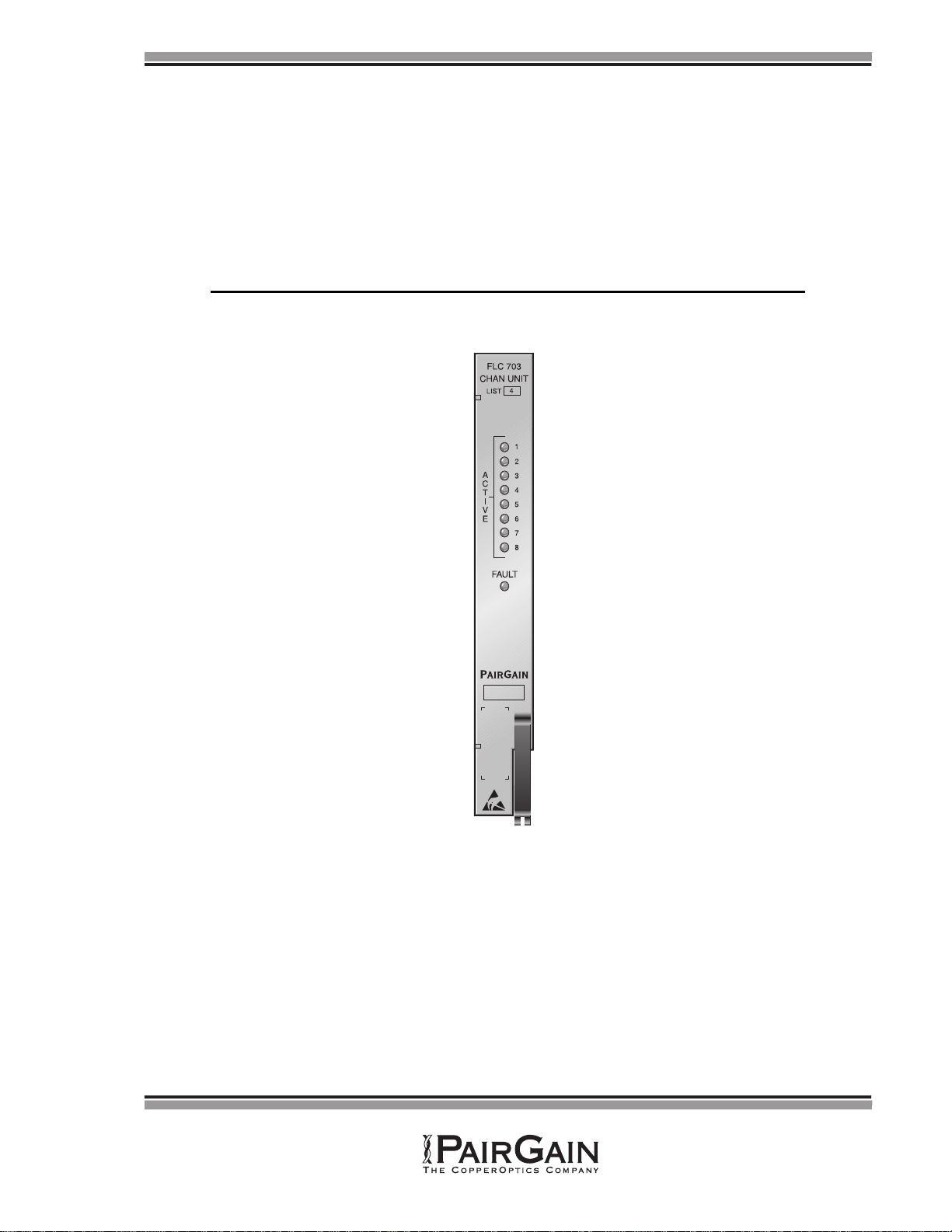
Page 8 PairGain Engineering - Plant Series PG-Flex FLC-703
Table 2. FLC-703 COT Channel Unit Troubleshooting
Indication Problem Action
FAULT LED
ON The FLC-703 processor has
detected a fault. Remove and re-insert the Channel Unit. If the FAULT LED does not
extinguish, replace the Channel Unit.
Troubleshooting based on customer-originated trouble reports
No Dial tone,
Can’t Dial
• fault
y
RT or COT
Channel Unit
• facility short/open
• CO switch problem
1Lift the subscriber
p
air at the network interface. If dial tone is
p
resent
and
y
ou can
p
lace a call, refer the
p
roblem to the customer
p
er local
practice.
2If
y
ou cannot hear dial tone or cannot
p
lace a call at the network
interface (with the subscriber
p
air lifted), check for dial tone at the RT.
If dial tone is
p
resent, check the
p
air between the RT and the network
interface. If no dial tone is present, replace the RT Channel Unit.
3If the
p
roblem still exists, re-insert the ori
g
inal RT Channel Unit and
replace the COT Channel Unit. Test for operation.
4If the problem still exists, refer the problem to the CO switch.
Phone Doesn’t
Ring
•hi
g
h-resistance
subscriber line short
• fault
y
RT or CO
Channel Unit
• loop length too long
1Lift the subscriber
p
air at the network interface. If rin
g
in
g
is
p
resent,
refer the problem to the customer per local practice.
2If rin
g
in
g
is not
p
resent, check for rin
g
in
g
at the RT. If rin
g
in
g
is
p
resent, check the
p
air between the RT and the network interface. If no
rin
g
in
g
is
p
resent, re
p
lace the RT Channel Unit. If rin
g
in
g
is still not
p
resent, check a circuit on another Channel Unit. If rin
g
in
g
is still not
present, replace the Line Unit.
3If rin
g
in
g
is still not
p
resent at the RT, re-insert the ori
g
inal Channel
Unit and Line Unit. Test for ringing at the COT.
4Test for rin
g
in
g
into the COT from the CO switch. If no rin
g
in
g
is
p
resent, refer the trouble to the CO switch. If rin
g
in
g
is
p
resent, re
p
lace
the COT Channel Unit. Test a
g
ain for rin
g
in
g
at the network interface.
If rin
g
in
g
is still not
p
resent, contact PairGain technical assistance
p
er
section 9.
5Verif
y
the resistance of the co
pp
er loo
p
between the RT Enclosure and
the network interface is less than 530 Ω.
Phone doesn’t
stop ringing
• fault
y
subscriber
instrument
• faulty RT Channel Unit
• loop length too long
1Test for rin
g
tri
p
at the network interface. If the rin
g
in
g
is tri
pp
ed, refer
the trouble to the customer per local practice.
2If the rin
g
in
g
is not tri
pp
ed, test for tri
pp
in
g
at the RT. If rin
g
tri
p
does
occur, check the loo
p
for excessive len
g
th. If rin
g
tri
p
does not occur,
re
p
lace the RT Channel Unit. If rin
g
tri
p
still does not occur, contact
PairGain technical assistance per section 9.
3Verif
y
the resistance of the co
pp
er loo
p
between the RT Enclosure and
the network interface is less than 530 Ω.
Can’t Hear,
Can’t Be
Heard
• subscriber problem
• fault
y
RT or COT
Channel Unit
1Lift the subscriber line at the network interface and check the si
g
nal
level. If correct, refer trouble to the customer per local practice.
2If the level is too low, check the level at the RT. If the level is correct
at the RT, check the
p
air between the RT and the network interface. If
the level is too low at the RT, replace the RT Channel Unit.
3If the level is still too low, re-insert the original RT Channel Unit.
4Check the level at the COT comin
g
from the CO switch. If it is correct,
re
p
lace the COT Channel Unit. If it is not correct, refer the
p
roblem to
the CO regarding the switch.
5If the level is still not correct, re-insert the ori
g
inal COT Channel Unit.
Contact PairGain technical assistance per section 9.

Revision 01 June 5, 1997 Section 363-703-104
PG-Flex FLC-703 PairGain Engineering - Plant Series Page 9
D. TECHNICAL SUPPORT
9. Technical Support
9.1 PairGain Technical Assistance is available 24-hours-a-day, 7-days-a-week by contacting PairGain
Customer Service Engineering group at:
Telephone: (800) 638-0031 or (714) 832-9922
Fax: (714) 832-9924
9.2 During normal business hours (8:00 AM to 5:00 PM, Pacific Time, Monday - Friday, excluding
holidays), technical assistance calls are normally answered directly by a Customer Service Engineer.
At other times, a request for technical assistance is handled by an on-duty Customer Service
Engineer through a callback process. This process normally results in a callback within 30 minutes
of initiating the request.
9.3 In addition, PairGain maintains a computer bulletin board system for obtaining current information
on PairGain products, product troubleshooting tips and aids, accessing helpful utilities, and for
posting requests or questions. This system is available 24-hours-a-day by calling (714) 730-3299.
Transmission speeds up to 28.8 kbps are supported with a character format of 8-N-1.
E. CERTIFICATION AND WARRANTY
10. Certification
10.1 FCC Compliance. The FLC-703 List 4 Channel Unit complies with the limits for Class A digital
devices pursuant to Part 15 of the FCC rules. These limits are designed to provide reasonable
protection against harmful interference when the equipment is operated in a commercial
environment. This equipment generates, uses and can radiate radio frequency energy and, if not
installed and used in accordance with the instruction manual, may cause harmful interference to
radio communications. Operation of this equipment in a residential area is likely to cause harmful
interference in which case the user will be required to correct the interference at his own expense.
10.2 Refer to the installation section of the appropriate instruction manual for the unit you are installing to
get information on:
•cabling
•proper connections
•grounding
•line power
10.3 All wiring external to the product(s) should follow the provisions of the current edition of the
National Electrical Code.

Section 363-703-104 June 5, 1997 Revision 01
Page 10 PairGain Engineering - Plant Series PG-Flex FLC-703
11. Warranty
11.1 PairGain Technologies warrants this product to be free of defects and to be fully functional for a
period of 5 years from the date of original shipment, given proper customer installation and regular
maintenance. PairGain will repair or replace any unit without cost during this period if the unit is
found to be defective for any reason other than abuse or improper use or installation.
11.2 This module should not be field repaired. If it fails, replace it with another unit and return the faulty
unit to PairGain for repair. Any modifications of the unit by anyone other than an authorized
PairGain representative will void the warranty.
11.3 If a unit needs repair, call PairGain for a Return Material Authorization (RMA) number and return
the defective unit, freight prepaid, along with a brief description of the problem, to:
PairGain Technologies, Inc.
14402 Franklin Avenue
Tustin, California 92780-7013
ATTN: Customer Repair Facility
11.4 PairGain will continue to repair faulty modules beyond the warranty program at a nominal charge.
Contact your PairGain sales representative for details and pricing.

Revision 01 June 5, 1997 Section 363-703-104
PG-Flex FLC-703 PairGain Engineering - Plant Series Page 11
F. ABBREVIATIONS
12. Abbreviations
CLASS Custom Local Area Signaling Services
CO Central Office
COT Central Office Terminal
DTMF Dual Tone Multi Frequency
MLT Mechanized Loop Testing
PBX Private Branch Exchange
PCM Pulse Code Modulation
PGTC Pair Gain Test Controller
POTS Plain Old Telephone Service
RMA Return Material Authorization
RT Remote Terminal

Other manuals for FLC-703
2
This manual suits for next models
1
Table of contents
Other PairGain Power Supply manuals
Popular Power Supply manuals by other brands

BANGGOOD
BANGGOOD LM317 Installment instructions

Elektro-Automatik
Elektro-Automatik PSI 8000 3U HS PV Series operating guide

TDK-Lambda
TDK-Lambda Alpha 1500 Handbook

Horizont
Horizont farmer AN1000 Solar instruction manual

EVGA
EVGA SuperNOVA 650P2 PLATINUM Series user manual

Vents
Vents PA 01 E Operation manual