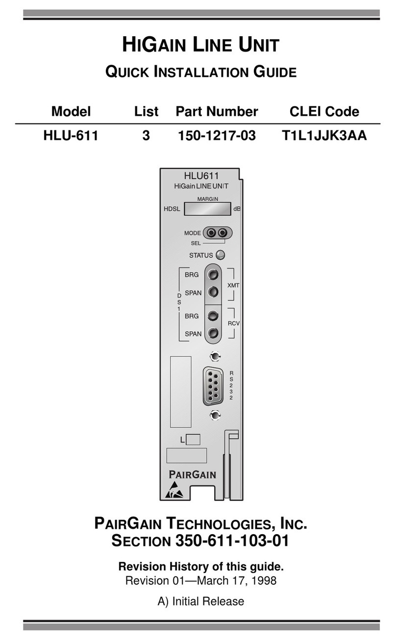
PairGain HiGain Wideband System 3190 User manual

PGT I
ESTP
S
AIR AIN ECHNOLOGIES, NC.
NGINEERING ERVICES ECHNICAL RACTICE
ECTION
™800-357-100-01v¨
800-357-100-01
HMS-357
HMS-357
Model List Number Part Number CLEI Code
1
2150-2205-01
150-2205-02 T3M1FH0ERA
T3M1GH0ERA
HiGain
Installation Guide
HiGain
Wideband System 3190

800-357-100-01, Revision 01
ii February 2, 1999 HMS-357 List 1
Revision History of This Practice
©Copyright 1999 PairGain Technologies, Inc.
Information contained in this document is company private toPairGain Technologies,Inc., and shall not bemodified, used, copied,
reproduced or disclosed in whole or in part without the written consent of PairGain.
Trademarks
PairGain and HiGain are registered trademarks of PairGain Technologies, Inc.
Other product names mentioned in this practice are used for identification purposes only and may be trademarks or registered
trademarks of their respective companies.
Disclaimer
Information furnished by PairGain Technologies is believed to be accurate and reliable. However, no responsibility is assumed by
PairGain Technologies for its use; nor for any infringement of patents or other rights of third parties which may result from its use.
No license is granted by implication or otherwise under any patent or patent rights of PairGain Technologies. PairGain
Technologies reserves the right to change specifications at any time without notice.
Revision Release Date Revisions Made
01 February 2, 1999 Initial Release

800-357-100-01, Revision 01 Using This Technical Practice
HMS-357 List 1 February 2, 1999 iii
USING THIS TECHNICAL PRACTICE
The following conventions are used in this manual:
•Monospace type indicates screen text, including text you type at a screen prompt.
•Keys you press are indicated by small icons such as . Key combinations to be pressed simultaneously
are indicated with a plus sign as follows: + .
•Two types of messages, identified by icons, appear in text.
ABOUT THIS MANUAL
This manual provides an overview of the HiGain Wideband System 3190, its features, applications, and main
system components.
Step-by-step installation instructions begin on page 13 and lead you through basic system setup and provisioning.
•For detailed information about specific system components, refer to the technical practice for that component.
•For comprehensive provisioning information, refer to “Provisioning Reference” on page 43.
This manual also contains Wideband System 3190 specifications and guidelines for troubleshooting.
If you have comments or questions about this Technical Practice, send email to technical_publications
@pairgain.com. Type the product name and document “section” number in the subject area of the email message.
RELATED DOCUMENTATION
Notes contain information about special circumstances.
Cautions indicate the possibility of equipment damage or the possibility of personal injury.
Document Number Title
400-100-100-xx TL1 Command Set Reference
150-357-200-xx HXU-357 List 1 HiGain Multiplexer Unit
150-357-100-xx HFA-357 List 1 HiGain Fan Assembly Unit
100-319-200-xx HTC-319 List 1 Test Card
150-319-107-xx HMU-319 List 7 and 7A
For information about line units, doublers, remotes and management units, refer to the appropriate
practice for the product model number.
(17(5
&75/
(6&

Related Documentation 800-357-100-01, Revision 01
iv February 2, 1999 HMS-357 List 1

800-357-100-01, Revision 01 Table of Contents
HMS-357 List 1 and List 2 February 2, 1999 v
TABLE OF CONTENTS
Product Overview_____________________________________________________________________ 1
Features..............................................................................................................................................2
Application.........................................................................................................................................2
Product Description............................................................................................................................3
Chassis.................................................................................................................................4
Multiplexer Unit ..................................................................................................................5
System Management Unit ...................................................................................................6
HiGain Line Units ...............................................................................................................7
HiGain Test and Loop-through Card...................................................................................8
HiGain Remote Units ..........................................................................................................9
HiGain Doubler Units..........................................................................................................9
Fan Assembly ....................................................................................................................10
Interfaces ...........................................................................................................................11
Alarms ...............................................................................................................................12
A/B Power Sources............................................................................................................12
Fuses..................................................................................................................................12
Installation__________________________________________________________________________ 13
Unpacking and Inspection................................................................................................................13
Safety Precautions............................................................................................................................13
Power Requirements........................................................................................................................13
Method of Procedure........................................................................................................................15
Installation Tools..............................................................................................................................15
Summary of Installation Tasks ........................................................................................................16
Installing a Chassis in a Standard Rack ...........................................................................................18
Mounting the Chassis ........................................................................................................19
Setting Up a 10BASE-T Configuration.............................................................................21
Powering the 3190 Chassis................................................................................................23
Installing a HiGain Management Unit.............................................................................................24
Connecting a Local Maintenance Terminal for Line Management...................................25
Connecting a Dial-Up Modem for Line Management.......................................................26
Configuring the HiGain Management Unit .....................................................................................26
Setting the HMU Date and Time (Option H) ....................................................................27
Setting the Shelf Identifier (Option D)..............................................................................27
Setting the Local IP Address (Option A)...........................................................................28
Setting the Ethernet Connection (Option G) .....................................................................28
Installing a Fan Assembly................................................................................................................29

Table of Contents 800-357-100-01, Revision 01
vi February 2, 1999 HMS-357 List 1 and List 2
Installing the Multiplexer Cards...................................................................................................... 31
Setting up the Communications Channel to the HXU-357............................................... 32
Setting up System Administration .................................................................................... 32
Configuring the HXU DS3 Interface................................................................................ 33
Placing the HXU DS3 Interface In Service ...................................................................... 33
Configuring the HXU DS1 Interface...............................................................................................34
Installing a HiGain Line Unit.......................................................................................................... 35
Installing a HiGain Doubler Unit.................................................................................................... 37
Installing a HiGain Remote Unit..................................................................................................... 38
Placing the Line in Service.............................................................................................................. 39
Placing the HLU Under HMU Management .................................................................... 39
Placing the Line in Service at the HXU............................................................................ 40
Viewing Performance at the HXU .................................................................................................41
Provisioning Reference________________________________________________________________ 43
Connecting a Maintenance Terminal...............................................................................................43
Accessing the Management Interface..............................................................................................44
Connecting a Local Terminal............................................................................................ 45
Connecting a Remote Terminal ........................................................................................ 46
Testing and Configuring a Remote Modem...................................................................... 48
Connecting the Remote PC Modem.................................................................................. 49
Logging on to the Management Interface......................................................................... 50
Navigating the Network Status Screen ............................................................................. 51
Navigating the Shelf Status Screen................................................................................... 52
Accessing the Shelf Options Menu ................................................................................................. 55
Configuring Shelf Management...................................................................................................... 56
Setting the Local IP Address (Option A).......................................................................... 57
Setting the Local Subnet Mask (Option B)....................................................................... 57
Setting the Default Gateway IP Address (Option C)........................................................ 57
Setting the Shelf Identifier (Option D) ............................................................................. 58
Setting the Mux Port (Option E)....................................................................................... 58
Resetting the HMU (Option F) ......................................................................................... 58
Setting the Ethernet Connection (Option G)..................................................................... 59
Setting the Date and Time (Option H).............................................................................. 59
Setting Fan Monitoring (Option K) .................................................................................. 59
Saving Settings (Option X)............................................................................................... 60
Configuring the Multiplexer Unit.................................................................................................... 60

800-357-100-01, Revision 01 Table of Contents
HMS-357 List 1 and List 2 February 2, 1999 vii
Managing Alarms.............................................................................................................................69
HMU Alarms.....................................................................................................................69
HXU Alarms......................................................................................................................69
When an Alarm Occurs .....................................................................................................70
Shelf Alarms for Multishelf Configurations......................................................................70
Line Unit Alarms...............................................................................................................71
Changing the Logon Password ........................................................................................................71
Logging Off......................................................................................................................................73
Troubleshooting _____________________________________________________________________ 74
Installing a HiGain Test Card ..........................................................................................................75
Appendix A - System Specifications _____________________________________________________ 76
Interface Specifications....................................................................................................................76
HXU-357 Multiplexer Card Specifications .....................................................................................80
DSX-1 Interface (CO Side)..............................................................................................................80
HDSL Transmission.........................................................................................................................81
System..............................................................................................................................................81
Span..................................................................................................................................................81
Test and Loopback...........................................................................................................................81
User Interfaces .................................................................................................................................81
Environmental Specifications ..........................................................................................................82
Physical Specifications ....................................................................................................................82
Power Specifications........................................................................................................................82
Compliance Standards......................................................................................................................85
Appendix B - Technical Reference ______________________________________________________ 86
Compatibility ...................................................................................................................................86
HiGain System Products..................................................................................................................86
Upgrading the Multiplexer Software ...............................................................................................87
Accessing the System Administration Screen...................................................................87
Verifying the Multiplexer IP Address...............................................................................87
Setting the Download Filename ........................................................................................88
Setting the Server IP Address............................................................................................88
Beginning the Software Download....................................................................................88
Burning in the Flash RAM to Complete the Software Update..........................................88
Alarms..............................................................................................................................................89
HXU-357 Default Software Settings ...............................................................................................91
Restoring HXU-357 Factory Defaults .............................................................................................92
HXU-357 DS1 / DS3 Interface Mode Descriptions.........................................................................93

Table of Contents 800-357-100-01, Revision 01
viii February 2, 1999 HMS-357 List 1 and List 2
Network Addresses.......................................................................................................................... 94
Hardware Addresses and IP Addresses............................................................................. 94
Subnet Mask...................................................................................................................... 94
Routers or Gateways......................................................................................................... 95
Trap IP Address ................................................................................................................ 95
Appendix C - Service and Support ______________________________________________________ 96
Technical Support............................................................................................................................ 96
BBS................................................................................................................................... 96
World Wide Web .............................................................................................................. 96
Returns.............................................................................................................................. 97
Bar Code Label and Configuration Number ................................................................................... 98
Appendix D - Glossary ________________________________________________________________ 99
Index______________________________________________________________________________ 101
Certification and Warranty_______________________________________________ Inside Back Cover

800-357-100-01, Revision 01 List of Figures
HMS-357 List 1 and List 2 February 2, 1999 ix
LIST OF FIGURES
1. HiGain Wideband System 3190................................................................................................................1
2. HiGain Wideband System 3190 Application............................................................................................2
3. Front View of 3190 Chassis (Cover Removed)........................................................................................4
4. HXU-357 Multiplexers .............................................................................................................................5
5. HMU-319 List 7 and List 7A....................................................................................................................6
6. Typical HLU-319 Line Unit......................................................................................................................7
7. HTC-319 List 1 Test and Loop-through Card...........................................................................................8
8. Fan Assembly..........................................................................................................................................10
9. Wideband System 3190 Interfaces (Backplane View)............................................................................11
10. Typical Six-lineup Floor Plan .................................................................................................................14
11. Summary of Installation Tasks................................................................................................................16
12. Typical Installation in a CO Rack...........................................................................................................18
13. Mounting the Wideband System 3190 in a CO Rack .............................................................................19
14. Wideband System 3190 (Backplane View) ............................................................................................20
15. Standalone 10BASE-T Configuration.....................................................................................................21
16. Multishelf 10BASE-T Configuration......................................................................................................22
17. TB1 Power Connector.............................................................................................................................23
18. HMU-319 Installation.............................................................................................................................24
19. Connecting a Terminal to the HMU Craft Port.......................................................................................25
20. Installing the Fan Assembly (Cover Removed)......................................................................................29
21. Installing the HXU-357 Multiplexer Cards.............................................................................................31
22. Installing the HLU-319 into the Chassis.................................................................................................35
23. HLU-319 Maintenance Terminal Main Menu ........................................................................................36
24. Installing an HDU in a Remote Enclosure..............................................................................................37
25. HRU Installed in a Remote Enclosure ....................................................................................................38
26. Management Interface.............................................................................................................................44
27. Local Terminal Connection.....................................................................................................................45
28. Remote Terminal Connection .................................................................................................................46
29. Logon Screen...........................................................................................................................................50
30. Network Status Menu..............................................................................................................................51
31. Shelf Status Menu ...................................................................................................................................52
32. Shelf Options Screen for the HMU-319 List 7 .......................................................................................55
33. Root Menu...............................................................................................................................................60
34. Root Menu Options.................................................................................................................................62
35. Changing a Password from the Shelf Status Menu.................................................................................72
36. System Loopbacks and Test Access........................................................................................................74

List of Figures 800-357-100-01, Revision 01
x February 2, 1999 HMS-357 List 1 and List 2
37. Power Connector (TB1).......................................................................................................................... 76
38. Alarm Relays (TB2) ............................................................................................................................... 76
39. HDSL Loop Cable and Connector.......................................................................................................... 79
40. Location of Bar Code Label and Configuration Number....................................................................... 98

800-357-100-01, Revision 01 List of Tables
HMS-357 List 1 and List 2 February 2, 1999 xi
LIST OF TABLES
1. Main Chassis Components........................................................................................................................4
2. HXU-357 Multiplexer Indicators .............................................................................................................5
3. CSA Range................................................................................................................................................9
4. Wideband System 3190 Interfaces..........................................................................................................11
5. Installation Tools.....................................................................................................................................15
6. Summary of Installation Tasks................................................................................................................17
7. Shelf Options Menu Parameters .............................................................................................................56
8. Keyboard Commands..............................................................................................................................61
9. Configuration Management ....................................................................................................................63
10. Performance Management ......................................................................................................................65
11. Fault Management...................................................................................................................................65
12. System Configuration Status...................................................................................................................66
13. System Administration ...........................................................................................................................67
14. Shelf Alarm Messages.............................................................................................................................70
15. Line Unit Alarm Messages......................................................................................................................71
16. Test Access Points ..................................................................................................................................74
17. Relay Specifications................................................................................................................................77
18. RJ-45 Pinout for 10BASE-T Interface to HMU (J34) ............................................................................77
19. RS-232 DB-25 OSS Interface to HMU (DTE) - Male Connector..........................................................77
20. RS-232 DB-25 HMU Craft Interface (DCE) - Female Connector..........................................................78
21. RS-232 DB-25 AUX Interface to HMU (DTE)......................................................................................78
22. HDSL Loop Cable Connector Pinout and Color Code ..........................................................................79
23. HDSL Transport Line Configurations.....................................................................................................83
24. Common Equipment Power Consumption..............................................................................................83
25. Wideband System 3190 with Full Compliment of Card Types and Dual Multiplexers.........................84
26. Power Consumption and Power Dissipation for Multisystem Configurations.......................................84
27. Compliance Standards ............................................................................................................................85
28. HiGain System Products .........................................................................................................................86
29. Alarms ....................................................................................................................................................89
30. HXU-357 Default Software Settings.......................................................................................................91
31. DS1 Interface Mode Descriptions...........................................................................................................93
32. DS3 Interface Mode Descriptions...........................................................................................................93
33. Network Addressing................................................................................................................................94
34. Sample Class C IP Address Plan for the HMS-357................................................................................95
35. Bar Code Label and Configuration Number...........................................................................................98

List of Tables 800-357-100-01, Revision 01
xii February 2, 1999 HMS-357 List 1 and List 2

800-357-100-01, Revision 01 Product Overview
HMS-357 List 1 and List 2 February 2, 1999 1
PRODUCT OVERVIEW
The Wideband System 3190 (HMS-357 List 1 and List 2) combines an industry-standard M13 multiplexer
function with the PairGain®High-bit-rate Digital Subscriber Line (HDSL) distribution system, providing the
lowest-cost, T1 delivery systemavailable. The Wideband System3190 terminates 28 HDSL lines and multiplexes
them into a single DS3 line. The Wideband System 3190 accommodates separate multiplexing and management
functions that are independently configured, thus providing a common interface with an open architecture. This
open architecture allows any industry-compliant 3192 card to function in a managed DS3-based shelf. PairGain
recommends that third-party line units be certified for compliance in a Wideband System 3190 shelf.
The chassis incorporates the HiGain®3190 line units (HLUs) and a management unit (HMU), thereby providing
a common architecture that supports all system functions. The M13 multiplexer system provides a managed,
high-level, DS3 trunk interface at the Central Office (CO). Both Terminal Access Option (TAO) and Transaction
Language 1 (TL1) management systems are supported on X.25, 10BASE-T, and RS-232 interfaces. The
Wideband System 3190 also features standard alarm relay contacts and accepts a redundant A/B office battery
source.
The Wideband System 3190 (with a full complement of remote equipment) can be configured with up to six
chassis (up to 168 lines) in a 7-foot rack and meet NEBS requirements for CO equipment.
Figure 1. HiGain Wideband System 3190

Product Overview 800-357-100-01, Revision 01
2 February 2, 1999 HMS-357 List 1 and List 2
FEATURES
Key features of the Wideband System 3190 are:
•Low cost per port
•Compatibility with industry-standard DS3 trunk circuits
•Compatibility with industry-standard 3192 channel cards
•Integrated open-management system based on PairGain’s single-wire management of HLU cards
•Compatibility with existing HiGain line units, doublers, and remote units
•NEBS and UL compliance at a system level
•Support for two CO-supplied -48 Vdc power sources
•Integrated HDSL distributions system and M13 multiplexing system
•Dual multiplexer for reliability with optional 1+1 protection on the DS3 interface
APPLICATION
By incorporating the M13 function into the Wideband System 3190, substantial savings are achieved on the
network side of the installation. Instead of 28 DSX1 lines connected to an office digital cross-connect system,
now only one DS3 interface is required. This results in a minimum savings factor of five at this interface.
Figure 2. HiGain Wideband System 3190 Application

800-357-100-01, Revision 01 Product Overview
HMS-357 List 1 and List 2 February 2, 1999 3
The HiGain Wideband System 3190 offers:
•A complete set of system-level products to current customers for the delivery of T1 from a DS3 trunk that
assures the lowest costs available
•A lower-cost solution to new customers for remotely provisioned T1 services
•An “open architecture” based on the standard 3190 channel card
•Simple, repeaterless T1 HDSL line installation to quickly meet any unanticipated demand for T1 services
PRODUCT DESCRIPTION
This section provides a brief description of the major components that comprise a Wideband System 3190:
Chassis (HMS-357) page 4
Multiplexer units (HXU-357) page 5
System management unit (HMU-319) page 6
HDSL units
HiGain Line Units (HLU-319)
HiGain Test Card (HTC-319)
HiGain Remote Units (HRU)
HiGain Doubler Units (HDU)
page 7
page 8
page 9
page 9
Optional fan assembly (HFA-357) page 10
Interfaces page 11
Alarms page 12
Fuses page 12
For more complete information aboutthe HXU-357, the HFA-357, the HMU-319, and thevarious HDSL
units, refer tothe appropriate practices for those products. See“Appendix C - Service and Support”
on page 96 for information on how to contact PairGain Technologies, Inc.

Product Overview 800-357-100-01, Revision 01
4 February 2, 1999 HMS-357 List 1 and List 2
Chassis
•Product Name: HMS-357 List 1 and List 2
•Part Number: 150-2205-01, 150-2205-02
Figure 3. Front View of 3190 Chassis (Cover Removed)
The chassis provides an interface for management functions and subscriber lines. Its main components are
described in Table 1.
Table 1. Main Chassis Components
Component Description
Heat baffle / fiber tray The upper heat baffle diverts heat out the back of the chassis. An optional fiber tray can be
field-mounted to the front-top of this unit to facilitate fiber routing.
3190 Shelf This standard 3190 shelf provides for up to 28 T1 ports to the field with common management.
Heat baffle / fan tray The heat baffle/fan tray provides cooling for the dual multiplexer tray and accepts an optional fan
assembly for additional cooling.
Dual multiplexer tray This tray accepts two HXU-357 multiplexer cards in a 1 + 1 protection scheme that provides both
DS3 and DSX1 protection.
ESD strap input Wrist-strap input for protection against electrostatic discharge.
12 in. (30.5 cm)
12
Dual M13 tray
Heat baffle /
fan tray
3190 shelf
Heat baffle /
fiber tray
18
ESD strap input
in. (30.8 cm)
38
21 in.
(54.3 cm)

800-357-100-01, Revision 01 Product Overview
HMS-357 List 1 and List 2 February 2, 1999 5
Multiplexer Unit
•Product Name: HXU-357 List 1
•Part Number: 150-2206-01
Figure 4. HXU-357 Multiplexers
There are two multiplexer cards mounted in the multiplexer tray. One is the active card and the other serves as a
backup if the active card fails. These self-contained units are capable of multiplexing 28 DS1 channels into a
single,industry-standard, DS3 data channel. The multiplexer cards provide several LED indicators for monitoring
power and alarm status. Figure 4 identifies the location of these indicators, which are visible on the front panel of
the chassis. Table 2 describes the various indicators.
Table 2. HXU-357 Multiplexer Indicators
Indicator Name Illuminates when . . .
FAULT (red) Fault a critical (CR), major (MJ) or minor (MN) alarm condition exists.
ABNORMAL (yellow) Abnormal an external status condition exists.
ACTIVE (green) Active the multiplexer is on-line.
CR (red) Critical a service-affecting fault exists or more than four DS1 inputs are removed or faulty.
MJ (red) Major a service-affecting fault exists or up to four DS1 inputs are removed or faulty.
MN (yellow) Minor a potentially service-affecting fault exists.
FE (yellow) Far End any remote alarm exists or a low-speed loopback is established at the far end.
PWR (green) Power power (A and B) is applied to the multiplexer card and the card is operating normally.
PWR A (green) Power Supply A -48 Vdc is being supplied to leg A of the power supply circuit. Located on the
connector edge of the multiplexer card.
PWR B (green) Power Supply B -48 Vdc is being supplied to leg B of the power supply circuit. Located on the
connector edge of the multiplexer card.
LB (yellow) Loopback a local DS1 or DS3 loopback is active.

Product Overview 800-357-100-01, Revision 01
6 February 2, 1999 HMS-357 List 1 and List 2
Using M13 or C-Bit framing, the HXU-357 is capable of transmitting and receiving up to 28 DS1 signals over an
electrical DS3 interface. The 28 DS1 channels provide a standard DSX-1 interface to the HXU-357. This allows
customer access to the DSX-1 interface using a standard 3190 cut-through card, such as the HTC-319, or through
the DSX-1 access jacks on the front of each HLU.
Dual HXU-357 cards provide full 1+1 protection (DSX-1/DS3). Through intracard communication the
microprocessors on each card maintain traffic when a switch fault condition is detected and control alarm contact
relays.
System Management Unit
•Product Name: HMU-319 List 7 and 7A
•Part Numbers: 150-1194-07 and 150-1194-71
Figure 5. HMU-319 List 7 and List 7A
The Wideband System 3190 is managed by PairGain’s standard HMU-319 management card. The HMU-319
provides network management and communication capabilities for HDSL T1 transmission service over
unconditioned copper wires.
•Provides line management functions for up to 32 shelves, each with a capacity of 28 line units
–Provisioning
–Retrieval of performance and alarm data
–Troubleshooting of line units
•Manages all system components (HLUs, HXUs, HDUs, and HRU).
Status LEDs
Alarm switch
Alarm Cut-Off LED
List number
HiGain MGT UNIT
HMU-319
ACO
ALM
MINOR
MAJOR
CRITICAL
EXT COMM
FAIL
POWER
R
S
2
3
2
L
RS-232 Craft port Barcode label
Alarm LEDs

800-357-100-01, Revision 01 Product Overview
HMS-357 List 1 and List 2 February 2, 1999 7
•Provides comprehensive management capabilities
–Basic Terminal Access Option (TAO) management software (HMU-319 List 7 and List 7A)
–TL1/TELNET management software (HMU-319 List 7A)
For complete details, refer to the practice for the HMU-319 List 7 and List 7A management unit.
HiGain Line Units
•Product Name: HLU-319 Lists 1, 2D, 2E, 5, and 5E
•Part Numbers: 150-1140-01, 150-1140-24, 150-1140-25, 150-1140-05, and 150-1140-55
Figure 6. Typical HLU-319 Line Unit
The HiGain HLUs provide a repeaterless, T1 transmission system to and from the CO. When installed in a System
3190 and used with a HiGain Remote Unit (HRU), each line unit delivers 1.544 Mbps transmission on two
unconditioned copper pairs over the full Carrier Service Area (CSA) range. The CSA includes loops up to
12,000 feet (3.658 km) of 24 AWG or 9,000 feet (2.743 km) of 26 AWG wire, including bridged taps. The HLU
can also be used in applications with HiGain Doubler Units (HDUs). For complete details, refer to the technical
practice for the HLU.
To obtain the latest update of the management software (which is required for managing the
multiplexer interface), contact Technical Support (see“Appendix C - Service and Support” onpage 96).
M
O
D
E
S
E
L
HLU-319
HiGain HD
L5E
R
C
V
B
R
G
M
A
R
G
I
N
(dB)
B
R
G
X
M
T
L
I
N
E
L
I
N
E
PairGain
R
S
2
3
2
System option buttons
Front panel display
Craft port
DSX-1 access jacks
Card handle
(warranty control numer
and CLEI code label on
outside of handle)
Status LED SETUP
STATUS

Product Overview 800-357-100-01, Revision 01
8 February 2, 1999 HMS-357 List 1 and List 2
HiGain Test and Loop-through Card
•Product Name: HTC-319 List 1
•Part Number: 150-1284-01
Figure 7. HTC-319 List 1 Test and Loop-through Card
The PairGain HTC-319 is an optional test card that plugs into any 3192 shelf slot. It provides access to test points
on CO, DSX-1, and field circuits. When used with the HXU-357 List 1, it features:
•Switch-selectable loopback, loopthrough, andtesting of Tip and Ring transmit and receive pairs for short and
open circuits (CO and field circuits)
•Test point access to Tip and Ring XMT and RCV circuits (CO and field), circuit ground, frame ground and
-48V power
•Current-limiting resistor in series with -48V test point protects power circuit from accidental shorting
•Miniature 210-jack access to CO and field circuits
•Normal DSX-1 access by routing the multiplexer DSX-1 port to the external lines (provides a normal DSX-1
interface at the main distribution frame for internal use)
See “Troubleshooting” on page 74 for information on system loopbacks and test points. See also “Installing a
HiGain Test Card” on page 75.
System 3190-compatible line units from other vendors will function in the HiGain
Wideband System 3190. In addition, cards that support PairGain’s single-wire per slot management
system can be managed by the Wideband System 3190. Please check with the vendor to ascertain
NEBS compliance.
A
B
C
D
E
F
G
H
I
J
K
SIDE 2
SIDE 1
T
T
T
T
RR
RR
CO
CO
FIELD
FIELD
TPA TPF
TP1 TP6
TP3
TP2
TP5 TPJ TP8
TP9
TPK
-48V
CIR
GRD
FRM
GRD
R1
LOOP
BACK
LOOP
THRU
SHORT
OPEN
PGAIR AIN
HTC-319 L1
TEST CARD
150-1284-01
FIELD
FIELD
FIELD
FIELD
C.O.
C.O.
C.O.
C.O.
TT
T
T
T
T
T
T
TT
T
T
T
T
T
R
RR
R
R
R
R
R
R
RR
R
R
R
R
R
SIDE 1
SIDE 1
SIDE 1
SIDE 1
SIDE 2
SIDE 2
SIDE 2
SIDE 2
LOOP BACK
LOOP THRU
SHORT
OPEN
FIELD
SIDE 2
C.O.
SIDE 1
1
S1
21
20 40
J1
T
Other manuals for HiGain Wideband System 3190
1
This manual suits for next models
1
Table of contents
Other PairGain Power Supply manuals