TIP
RING
LOCK
SLEEVE
ON-HOOK
PROCEED
TSTALM
TMAJ
SEIZE
SEZBY
SHELF ID
MAJ AUD
MAJ VIS
MIN AUD
MIN VIS
P
G
T
C
A
L
A
R
M
I
N
T
E
R
F
A
C
E
NO CNC
FSU 796
FPI STREAKER
LIST 4
1234
−48 CO
TEST
PG
AIR AIN
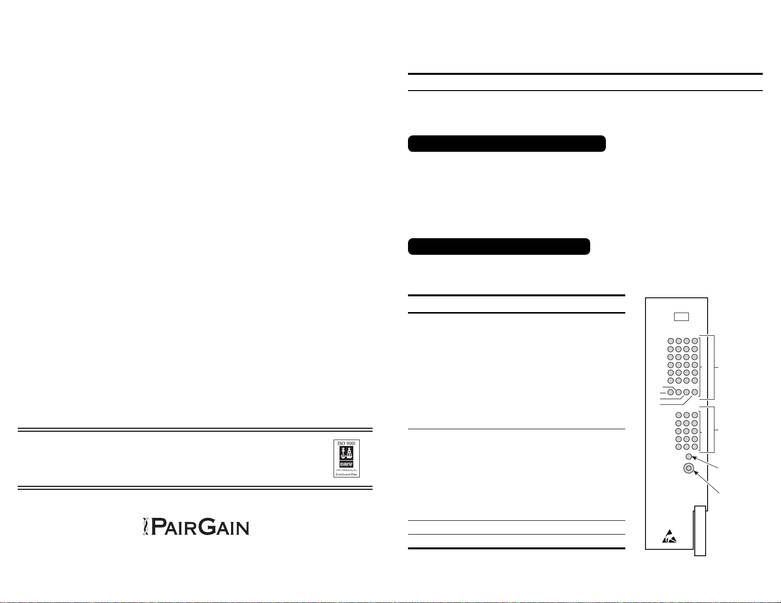
PGTC Interface
Status LEDs
Alarm Status
LEDs
Power LED
LED Test
Switch
PG-FLEX FPI STREAKER CARD
QUICK INSTALLATION GUIDE
This PairGain®PG-Flex™ FSU-796 List 4 FPI Streaker card is a continuity tester. The card verifies that the
PGTC interface and Alarm connections from the "MAINT UNIT" slot of a PG-Flex Central Office Terminal
(COT) shelf (19" or 23") are wired correctly to the Central Office (CO) Main Distribution Frame (MDF).
When you receive the PG-Flex FSU-796 List 4 streaker card:
1Unpack the PG-Flex FSU-796 streaker card and visually inspect it for signs of damage. If the components
have been damaged in transit, immediately report the extent of damage to the transportation company and
to your sales representative. Order a replacement unit if necessary.
2Compare the contents of the package against the packing list. If the shipment is incorrect, contact PairGain
as described in the "Limited Warranty" section.
The illustration shows the FSU-796 List 4 front panel, and the table below describes the features and functions
for the front panel LEDs and the LED Test switch.
MODEL FSU-796 LIST 4, P/N150-1396-04
Feature Function
PGTC Interface Status LEDs
TIP 1 - 4
RING 1 - 4
LOCK 1-4
SLEEVE 1 - 4
ON-HOOK 1 - 4
PROCEED 1 - 4
TSTALM
TMAJ
SEIZE
SEZBY
These 28 LEDs are used to verify the PGTC Interface
connections.
The appropriate LED lights when one of the 28 PGTC
Interface terminations from the MDF is shorted to
ground.
If the LED for the termination under test does not
light, or the wrong LED lights, the termination is
miswired.
Alarm Status LEDs
SHELF ID
MAJ AUD
MAJ VIS
MIN AUD
MIN VIS
These 15 LEDs are used to verify major and minor
visual and audible alarms.
The appropriate LED lights when one of the Alarm
terminations from the MDF is shorted to ground.
If the LED for the termination under test does not
light, or the wrong LED lights, the termination is
miswired.
For the relay contact, NO is normally open, C is
common, and NC is normally closed.
-48 CO LED Indicates that the CO battery is wired correctly.
LED Test Switch When pressed, lights all LEDs on the Streaker card.
Unpack and Inspect the Shipment
Features of the FSU-796 List 4
Technical Assistance
PairGain Technical Assistance is available 24 hours per day, 7 days per week by contacting PairGain’s Customer
Service Engineering group (listed below).
During normal business hours (8:00 AM to 5:00 PM, Pacific Time, Monday through Friday, excluding holidays),
technical assistance calls are normally answered directly by a Customer Service Engineer. At other times, a
request for technical assistance is handled by an on-duty Customer Service Engineer through a callback process.
This process normally results in a return call within 30 minutes of initiating the request.
In addition, PairGain maintains a computer bulletin board system for obtaining current information on PairGain
products, product fault isolation tips and aids, helpful utilities, and for posting requests or questions. This system
is available 24 hours per day by calling (714) 730-2800. Transmission speeds up to 28.8 kbps are supported with
a character format of 8-N-1.
PairGain product, company, and application information can be found at http://www.pairgain.com using any Web
browser.
Limited Warranty
PairGain Technologies, Inc. warrants this product to be free of defective and faulty workmanship for a period of
60 months, under normal use, from the date of shipment. PairGain's obligation under this warranty is limited to
replacing or repairing, at PairGain's option, any such product that is returned during the warranty period per
PairGain's instructions and which product, in PairGain's sole option, is determined to be defective upon
examination at our plant.
Do not try to repair or disassemble the unit. If it fails, replace it with another unit and return the faulty unit to
PairGain for repair. Any modifications of the unit by anyone other than an authorized PairGain representative will
void the warranty.
If a unit needs repair, call PairGain at (800) 638-0031 for a Return Material Authorization (RMA) number and
return the defective unit, freight prepaid, along with a brief description of the problem, to the PairGain
Technologies, Inc. at 14352 Franklin Avenue, Tustin, CA 92780-7013.
PairGain will continue to repair or replace faulty modules beyond the warranty program at a nominal charge.
Contact your PairGain sales representative for details and pricing.
FCC Compliance
This unit complies with the limits for Class A digital devices pursuant to Part 15 of the FCC rules. These limits
are designed to provide reasonable protection against harmful interference when the equipment is operated in a
commercial environment. This equipment generates, uses, and can radiate radio frequency energy and, if not
installed and used in accordance with the instruction manual, can cause harmful interference to radio
communications. Operation of this equipment in a residential area is likely to cause harmful interference, in which
case the user will be required to correct the interference at his own expense.
Refer to the installation section of the appropriate instruction manual for the unit you are installing to get
information on cabling, correct connections, and grounding.
Corporate Office: ForTechnicalAssistance:
14402 Franklin Avenue (800) 638-0031
Tustin, CA 92780
Tel: (714) 832-9922
FAX: (714) 832-9924
Copyright © 1998 PairGain Technologies Inc.
Section Number 363-796-104-01, Revision 01, June 24, 1998


