Web Management User Guide
- 1 -
WEB page operating manual
This manual focus on describing the WEB page of switch, the user can managed the switch
through WEB page. This manual only introduce the simple opetations of the various WEB page
of the various switches. This manual includes the following:
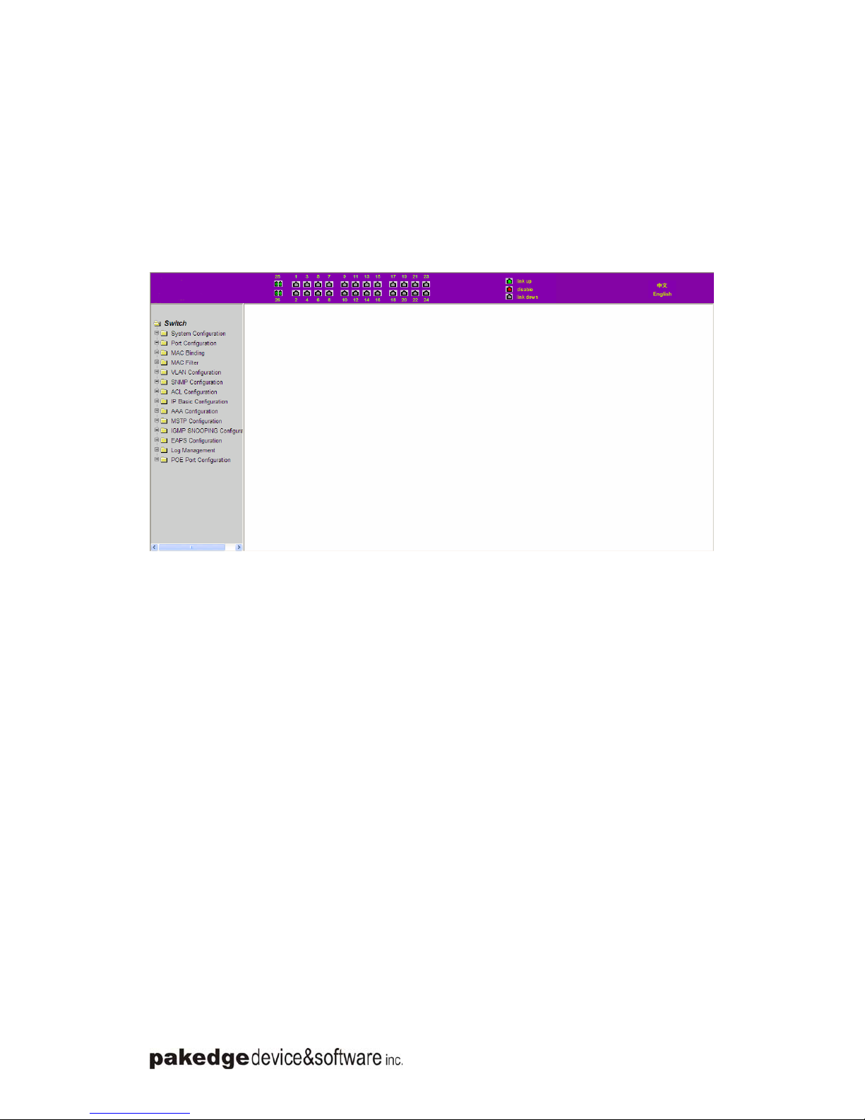
1, WEB page overview
2, WEB page description
Chapter 1、WEB page overview
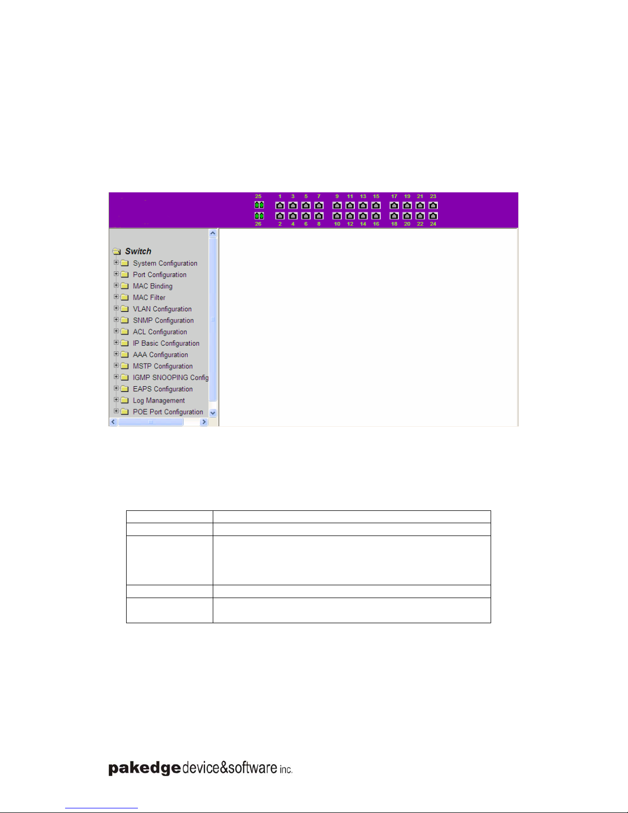
1、WEB Access features
zSwitch provide users with Web access functionality. Via Web browser, users can
access switches, manage and configure the switch. WEB accessing‘s main features
are:
1, Easy to access: Users can easily access on switch from anywhere using the
network.
2, users can visit the WEB pages of the switch by using the familiar Netscape λ
Communicator and Microsoft Internet Explorer and other browsers, WEB pages of
graphical and tabular format presented to the user.
3, Switch switch provides a wealth of WEB pages, the user can configure and manage
vast majority of functions of the switch.
4, WEB page’ function classification &integration, make the user find the relevant
pages to configuration and management.
2、WEB browsing system requirements
Pls see the form 1。
Form 1:
Hardware&Software system requirements
CPU Pentium 586 above
Memory 128MB above
Resolution 800x600 above
Color 256 colors above
Browser IE4.0 above or Netscape4.01 above
Operating system Microsoft® ,Windows95®,Windows98®,WindowsNT®,
Windows2000®,WindowsXP®,WindowsME®, WindowsVista®,
Linux,Unix ect.
Note:
Microsoft ®, Windows95 ®, Windows98 ®, WindowsNT ®, Windows2000 ®, WindowsXP ®,
Windows ME ®, WindowsVista ® is a registered trademark of Microsoft Corp. All other product
names, trademarks, registered trademarks and service marks, copyrights held by their respective
owners.
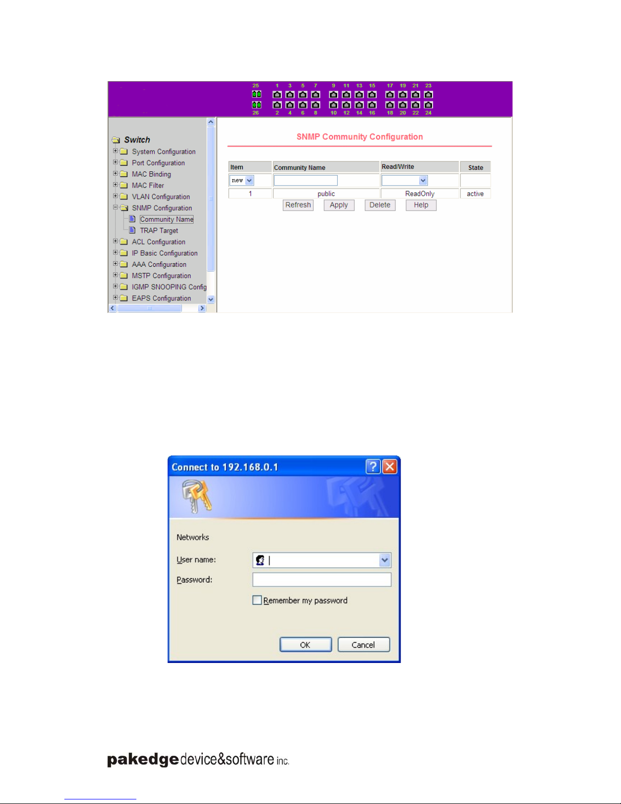
3、WEB browsing session landing
zBefore start Web browsing session ,the user need to make sure:
1. has configure the IP of switch, under the default case, the switch VLAN1 interface
IP address is 192.168.0.1,
2. subnet mask is 255.255.255.0.
3. has a Web browser installed on the host to connect to the network, and the host