Palas Promo 2000 User manual

OperationManual
Light‐scatteringspectrometer
Promo®2000

OPERATIONMANUALPROMO®2000
PALAS®GMBH,MARCH2010,VERSIONV0010320102
CONTENTS:
1IMPORTANTNOTES!!!.......................................................................................................4
2INSTALLATIONANDFIRSTOPERATION.............................................................................5
2.1Mainsvoltagecheck......................................................................................................5
2.2Auxiliaryequipmentcheck............................................................................................5
3CONNECTINGTHESENSOR................................................................................................6
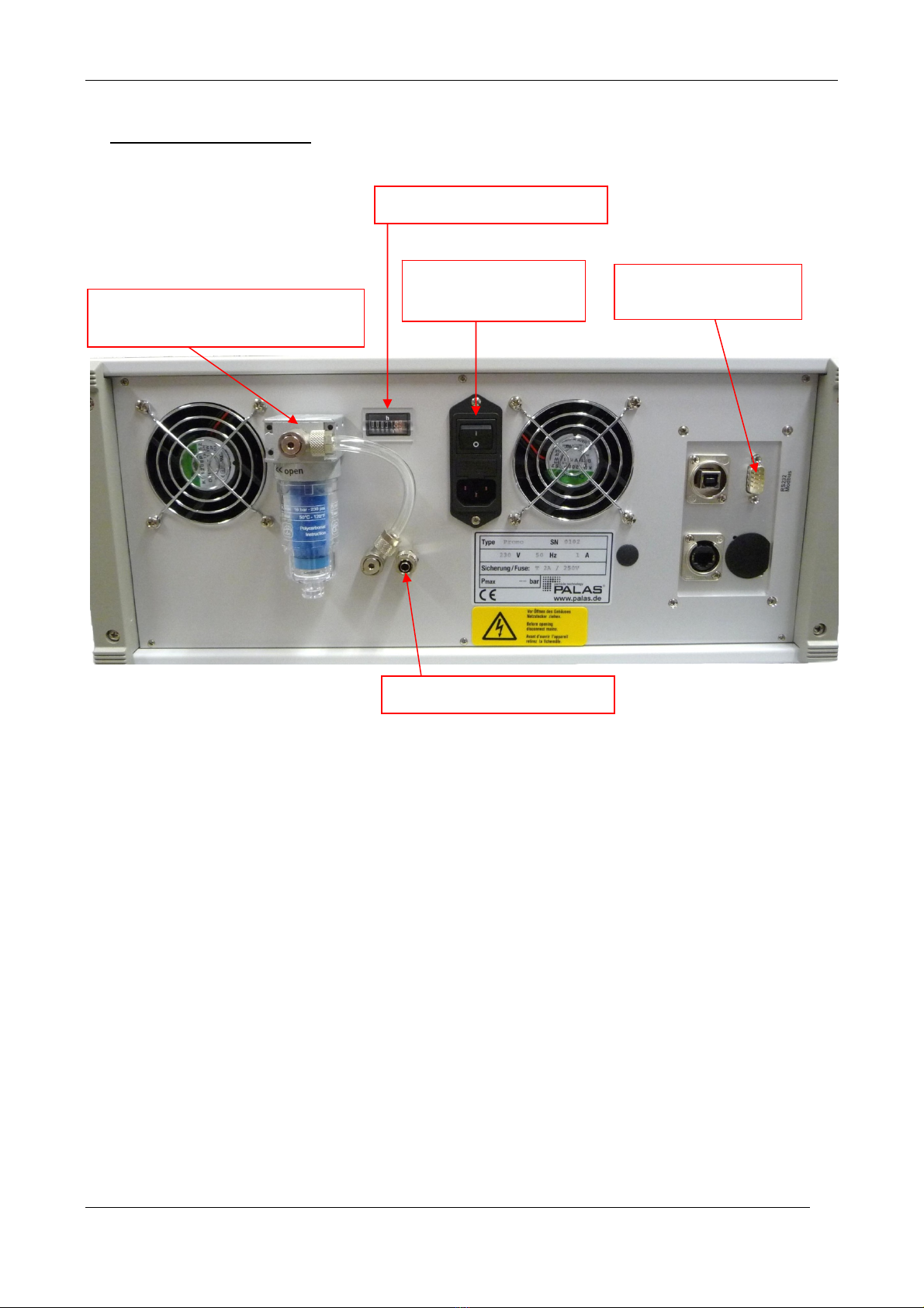
3.1Rearsideofthecontrolunit..........................................................................................6
3.2Frontsideofthecontrolunit.........................................................................................7
3.2.1Completeconnectionofthecontrolunit....................................................................8
3.3Connectionofthesensor..............................................................................................9
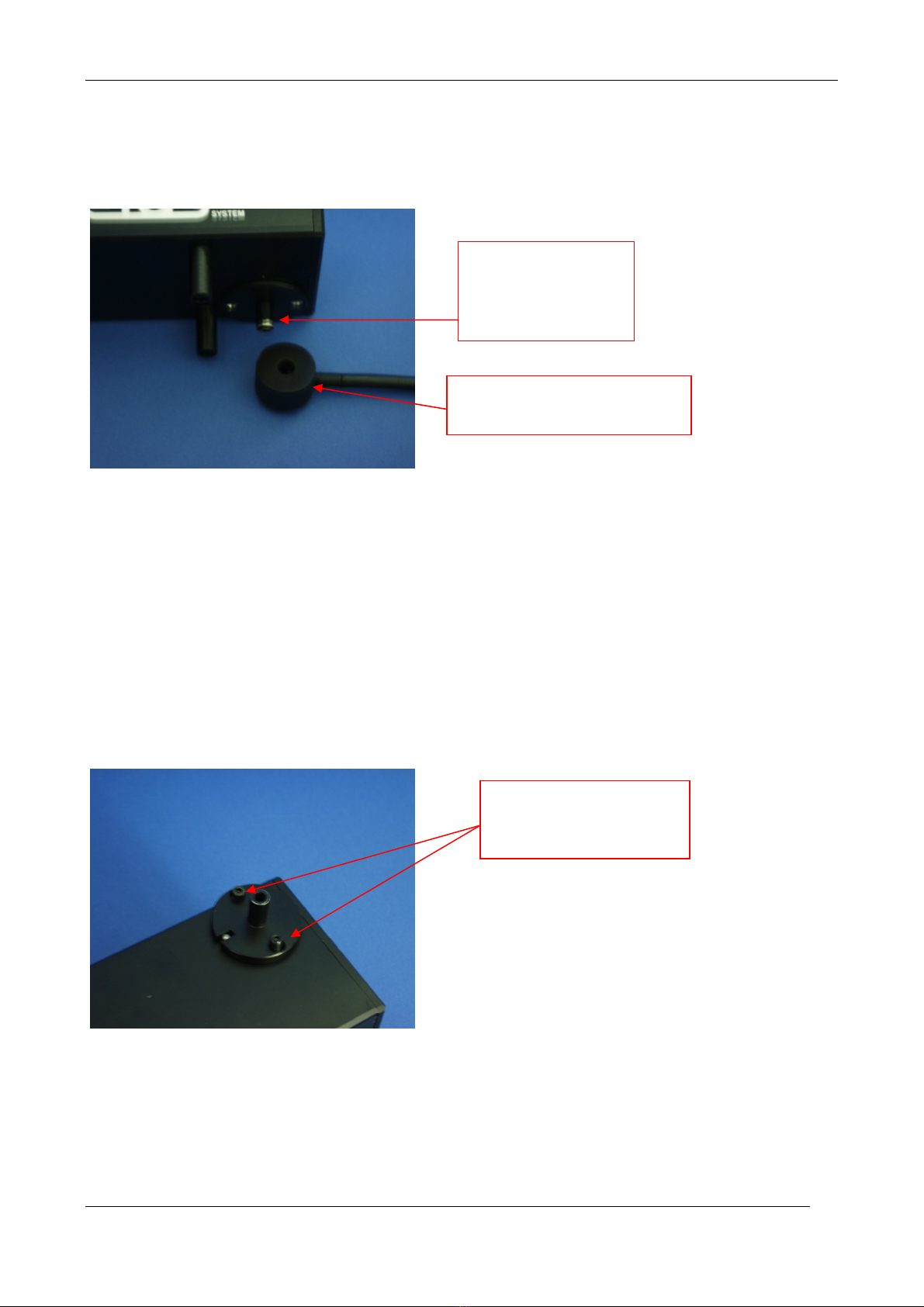
3.3.1Uppersideofthesensor............................................................................................9
3.3.2Bottomviewofthesensor.......................................................................................10
3.4Cleaningthesensor.....................................................................................................10
3.4.1Howtocleanthesensor..........................................................................................10
3.5Handlingoflightwaveconductorcables.....................................................................12
3.6Fibertest......................................................................................................................13
3.7Lampexchange...........................................................................................................15
3.8Lossofwarranty..........................................................................................................16
4CALIBRATIONOFTHESENSORWITHCALDUST1100.......................................................17
4.1HowtocalibrateyoursensorfortheselectedmeasurementrangewithCalDust1100?
18
4.2Calibrationofthevelocity:..........................................................................................19
5ENSURINGCORRECTTESTCONDITIONS..........................................................................20
5.1Measurementerrors...................................................................................................20
5.1.1Methodicerrors.......................................................................................................21
5.1.2Accidentalerrors.....................................................................................................21
5.1.3Agrosserror............................................................................................................21
5.2Importantcomparison................................................................................................22
5.3Erroridentificationofopticalmeasuringdevices.........................................................23
5.4Advantagesofcountingmeasuringprocedures...........................................................23
5.5Opticalparticlemeasurement.....................................................................................24
5.6Termsofopticalparticlemeasurement.......................................................................24
5.7Determinationofinteractionrelations........................................................................24
5.8Particlecharacteristics/Equivalentdiameter...............................................................25
5.8.1Particlecharacteristics............................................................................................25
5.8.2Equivalentdiameterof............................................................................................26
5.9Opticallimitationofthemeasuringvolume................................................................26
5.10Resolutioncapacityandclassificationaccuracy...........................................................27
6PARTICLEMEASUREMENTWITHPROMO®......................................................................28
6.1SpecialfeaturesofthePromo®system.......................................................................28
6.2Clearcalibrationcurve................................................................................................29

OPERATIONMANUALPROMO®2000
PALAS®GMBH,MARCH2010,VERSIONV0010320103
6.3Highresolutioncapacity..............................................................................................30
6.4Opticalmeasuringprinciple.........................................................................................31
6.5T‐aperturetechnology.................................................................................................32
6.6Borderzoneerror........................................................................................................33
6.7Impactofthedeviceparameters.................................................................................33
7OPTIONALEQUIPMENT:.................................................................................................35
CuvetteHeatingforwelas®digital1000,welas®digital2000,welas®digital3000,Promo®
2000,Promo®3000,welas®1000,welas®2000,welas®3000,PCS2010,PCS2000.................35
7.1Contents.....................................................................................................................35
7.1.1Function..................................................................................................................35
7.1.2Setupandcablingofthecuvetteheating.................................................................35
7.1.3MaintenanceandCleaning......................................................................................36
8TECHNICALDATA............................................................................................................39

OPERATIONMANUALPROMO®2000
PALAS®GMBH,MARCH2010,VERSIONV0010320104
1IMPORTANTNOTES!!!
Pleasecheckimmediatelyafterunpackingtheinstrumentifthereareobvioustransportation
damages.Ifanydamagesoftheinstrumentarevisible,don’tconnectittomainsanddon’t
switchiton.Callthemanufacturertocheckiftheinstrumentcanbeoperatedsafely.
ItisessentialtoreadtheoperatinginstructionsthoroughlybeforeoperatingPromo®!!
Themanufacturerisnotliablefordamagescausedbyimproperoperating,incorrectcleaning
orthemeasurementofaerosolswithagasconditionorcompositiontheinstrumentisnot
specifiedfor.
Theinstrumentmayonlybeoperatedindryroomsunderatmosphericenvironmentalpressure
andatroomtemperature.
Themanufacturerwillnotbeliablewithregardtotheoperatingguarantee,ifoperatingtakes
placeunderdifferentenvironmentalconditions,suchascorrosiveorexplosiveenvironment,
electricorelectromagneticfields,operatingwithinareasofionisingradiation,withinareas
conductivetoshockorvibration.
Toswitch‐offPromo®,usethe"shutdown"button;Promo®shutsdownthenautomatically.
Donotswitch‐offthemainsswitch,beforetheoperatingsystemshutdownautomatically!!!
Formeasurementsinoverpressureandunderpressure,apressure‐resistantcuvetteisneeded.
Thepressure‐resistantcuvettecanbeinstalledsubsequently.Forthis,theopticsofthesensors
hastobere‐adjustedonthepremisesofPalas®.
Thepressure‐resistantcuvetteisabletoworkunderoverpressureupto10bar.
Formeasurementsinhightemperaturesthepressure‐resistantcuvettecanbeoptionally
heatedupto120°C.
Attention:Itisnotallowedtouseawelas®sensorwithintegratedheatingin
explosiveareas!!!
Promo®wasmanufacturedforthesystemvoltagedefinedinthecorrespondentorder.Please
checkifthesystemvoltageindicatedontheidentificationplatecorrespondstothesystem
voltageattheplaceofoperation.
Onlyuseoriginalspareparts!Pleasecontactthemanufacturertoorderspareparts.
Attention:Aerosolsmightbedangeroustoyourhealth.That’swhytheyoughtnottobein‐
haled.Itmightalsobenecessarytowearprotectiveclothes.Pleasepayattentiontothecorre‐
spondentstandardsandsafetyrules.
GeneralinformationonOpticalParticleCounters,suchasresolutioncapacity,detectionlimit
andcountingefficiency,canbefoundintheVDI‐guideline3489,Part3.

OPERATIONMANUALPROMO®2000
PALAS®GMBH,MARCH2010,VERSIONV0010320105
2Installationandfirstoperation
2.1 Mainsvoltagecheck
ThePromo®wassetbythemanufacturertothemainsvoltagerequestedintheorder.Pleasever‐
ify,ifthemainsvoltageindicatedonthetypelabelcorrespondstothemainsvoltageatthere‐
spectiveplaceoftheinstallation.
Themanufacturerisnotliablefordamagesresultingfromoperationwithimpropermainsvolt‐
age!!!
2.2 Auxiliaryequipmentcheck
Pleasealsoverifyimmediatelyafterunpackingtheinstrument,ifthedeliveryofallauxiliary
equipmentiscomplete.Besidesthesensorandthecontrolunit,thefollowingpartsshouldbe
available:
Mainscableforcontrolunit
2opticalfibres(standardlength:3m)
1tubeforconnectionofinternalpumptothesensor
1cableRS232forModbusinterface(9‐poleplug)
1operationmanual
1CDwithsoftware
onlywithPromo®H(heatableand/orpressure‐resistant):specialkeytoremoveholderofopti‐
calglassesfromcuvette
1tubeforcalibrationandmeasurements
CalDust1100forcalibration

OPERATIONMANUALPROMO®2000
PALAS®GMBH,MARCH2010,VERSIONV0010320106
3Connectingthesensor
3.1 Rearsideofthecontrolunit
Connectthecontrolunittothemainssupplyusingthemainscable.Thecontrolunitisswitched‐on
andswitched‐offwiththeon/offswitch.
Donotswitch‐offtheon/offswitch,beforetheoperatingsystemshutdownautomatically!!!
Thelampisswitched‐onbytheon/offswitch.Theoperationhourcounterrunsaslongthepower
ison.Thelamphasastandardlifetimeof2000hours.Incaseofalampexchange,thehourrecord‐
inghastobenoteddownasitcannotbereset.
RS232Modbus
interface
Filterunittoprotecttheinternal
pumpfromtheaerosol
Powerconnection
withon/offswitch
Operatinghourscounter
Outletforsamplingflow

OPERATIONMANUALPROMO®2000
PALAS®GMBH,MARCH2010,VERSIONV0010320107
3.2 Frontsideofthecontrolunit
Attention:
Uponconnectionoftheopticalfibres,pleasepayatallcostsattentionthattheconnectionatthe
controlunitcorrespondswiththeconnectionofthesensor.Ifthecablesareconnectedtothe
wrongsocket,theopticalandelectroniccomponentsoftheinstrumentwillbedamaged!
Takecare:
BEFOREswitchingonthesupplyunit,allopticalfibresmustbeconnectedcorrectlytothesupply
unitandtothesensor!
Especiallywhendisconnectingtheopticalfibrefromthedetectorofthesupplyunit,thesupply
unitmustbeswitchedoff!
Anyfailuretocomplywiththeserulescanleadtodamagesofopticalandelectronicpartsofthe
lightdetector.
Thesocketbelowtheamperemeterservestotestthelampefficiencyofthelampandthefunc‐
tionalityoftheopticalfibre.Todosuchatest,theopticalfibreneedstobeconnectedfromthe
lampoutlettothementionedsocket.Iftheammetershows>0,5mA,thelampandthefibreare
ok.
Thesuctionisdonebyafixedvolumeflowof5l/min.
Connectionofpump
Connectionofdetector
Additional
connection
forlampand
opticalfibre
check
Connectionoflamp
withyellowlabelling
(lampoutlet)
Touchdisplay
USBconnection

OPERATIONMANUALPROMO®2000
PALAS®GMBH,MARCH2010,VERSIONV0010320108
3.2.1 Completeconnectionofthecontrolunit
Attention:
Uponconnectionoftheopticalfibres,pleasepayatallcostsattentionthattheconnectionatthe
controlunitcorrespondswiththeconnectionofthesensor.Ifthecablesareconnectedtothe
wrongsocket,theopticalandelectroniccomponentsoftheinstrumentwillbedamaged!
Takecare:
BEFOREswitchingonthesupplyunit,allopticalfibresmustbeconnectedcorrectlytothesupply
unitandtothesensor!
Especiallywhendisconnectingtheopticalfibrefromthedetectorofthesupplyunit,thesupply
unitmustbeswitchedoff!
Anyfailuretocomplywiththeserulescanleadtodamagesofopticalandelectronicpartsofthe
lightdetector.
Carefullyplugthecablesintothesocketandfixbyturningthescrewednuttotheright.
Thetubeofthepumpmustbeconnectedtothemarkedpumpsocketandisfixedbyturningitto
thefront.
Pumpconnection
Detectorconnection
Lampconnection
Detectorconnection
Lampconnection
Pumpconnection
AnschlussFibreTest
Aerosolinlet

OPERATIONMANUALPROMO®2000
PALAS®GMBH,MARCH2010,VERSIONV0010320109
3.3 Connectionofthesensor
3.3.1 Uppersideofthesensor
Attention:
Uponconnectionoftheopticalfibres,pleasepayatallcostsattentionthattheconnectionatthe
controlunitcorrespondswiththeconnectionofthesensor.Ifthecablesareconnectedtothe
wrongsocket,theopticalandelectroniccomponentsoftheinstrumentwillbedamaged!
Takecare:
BEFOREswitchingonthesupplyunit,allopticalfibresmustbeconnectedcorrectlytothesupply
unitandtothesensor!
Especiallywhendisconnectingtheopticalfibrefromthedetectorofthesupplyunit,thesupply
unitmustbeswitchedoff!
Anyfailuretocomplywiththeserulescanleadtodamagesofopticalandelectronicpartsofthe
lightdetector.
Carefullyplugthecablesintothesocketandfixbyturningthescrewednuttotheright.
Thetubeofthepumpmustbeconnectedtothemarkedpumpsocketandisfixedbyturningitto
thefront.
Aerosolinletconnection
Lampconnection
Detectorconnection
Opticalfibre
forlampcon‐
nection
Opticalfibrefordetector
connection
Connectionofthepump
tubeatthebottomsideof
t
h
e
se
n
so
r
Tubeofthepump
connection

OPERATIONMANUALPROMO®2000
PALAS®GMBH,MARCH2010,VERSIONV00103201010
3.3.2 Bottomviewofthesensor
Thetubeofthepump(plugconnection)ispluggedintothecorrespondentsocketatthebottom
sideofthesensor.
3.4 Cleaningthesensor
3.4.1 Howtocleanthesensor
First,removethepumptube(plugconnection)fromthesensorhousingatthebottomsideofthe
sensor(seepictureabove).Then,thetwohexagoncapscrewshavetobeloosened.Todoso,use
thecorrespondentwrench.
Afterthat,themeasuringvolumecanbetakenawayfromthesensor.Movetheaerosolguide
tubefromthebottomsideattheconnectionofthepumptubeslowlyupwards.
Pumptubewithconnection
forsensor
Connectionofthe
pumptubetothe
bottomsideofthe
sensor
Openthetwohexagon
screwsatuppersideof
thesensor

OPERATIONMANUALPROMO®2000
PALAS®GMBH,MARCH2010,VERSIONV00103201011
Cleantheopticalglassesinsidetheaerosolinletonlywithanopticalcloth.Nevertouchitwith
yourfinger.
Tocleantheaerosolguidetubeusepressurisedair.
Thesampleflowismeasuredanddisplayed.Thefilterelementinsidethefilterunitontheback
sideofthecontrolunithastobecleanedfromtimetotimeandshouldbechangediftheflowis
droppingbelowitsnominalvalue.
Attention:
Ifyouhaveasensorwithaspecialcuvette(welas®heatableand/orpressure‐resistant)youhaveto
removetheopticalglassesofthecuvettewithaspecialkeybeforeyoucleanthecuvettewith
pressurisedair.Cleantheopticalglassesofthecuvettealsoonlywithanopticalcloth.
Aerosolinlet–Usetheoptical
clothtocleanthetwooptical
glassesinside.
Aerosol guidingtube
Opticalclothtocleantheopti‐
calglasses

OPERATIONMANUALPROMO®2000
PALAS®GMBH,MARCH2010,VERSIONV00103201012
3.5 Handlingoflightwaveconductorcables
Whenremovingtheprotectivecappleaseholdthefibertotheplug.Donotholdittothefibercoatnorto
thefiberbendprotection!
Thefibermaynotbebenttooclosely.Themaximumbendingradiusof10cmshouldnotbeunder‐run.
Therightforcompensationdoesnotexistinthecaseofnaturalwearandtearordamagewhicharisesafter
thepassageofriskduetoincorrectorcarelesshandling,excessiveoperationaldemand,unsuitableequip‐
mentorduetospecialinfluences.

OPERATIONMANUALPROMO®2000
PALAS®GMBH,MARCH2010,VERSIONV00103201013
3.6 Fibertest
Withthefibertestyouareabletocheckwhetherthelightwaveconductorcableisinpropercon‐
dition.Todosoyouhavetoconnectthecablebetweenthelightsourceoutputandthefibertest
input.
Attention:
Nevereverdirectlyconnectthelightsourceoutputwiththedetectorinput;thismaycausese‐
veredamagetothedetector!
PleaseuseonthetouchscreenthebuttonAccessoirs.
Thisviewisshownbypressingthebutton“suctionpump/signals/digitalIO"inthemenuoverview.
Promo®hasaninternalcontrolanddataacquisitioncard.Thiscardcanoptionallybeusedforthe
followingpurposes:controloftheinternalpump,recordingofanalogueanddigitalsignals.
Promo®canalsobeequippedwithtwotemperaturecontrollers.Additionally,Promo®continu‐
ouslymeasuresthevelocityoftheflow/particleswithinthesensor.

OPERATIONMANUALPROMO®2000
PALAS®GMBH,MARCH2010,VERSIONV00103201014
Displayofthemeasureddata
whicharemeasuredwiththe
internaldataacquisitioncard
(humidity,differentialpres‐
sure,temperature,absolute
pressure,sensorvolumeflow).
Statusofthedigitalinputsand
outputs.Twoanaloguesignals
arenotspecific.
Ifthefiberisingoodconditionyouwillhaveacertainvoltageindicatedbytheneedle.Thevalue
howeverisdependingonthequalityofthelightsourceitselfbutshouldneverthelessalwaysbe
largerthan1V.
Withthistestyoucanalsocheckthequalityofyourlightsource.

OPERATIONMANUALPROMO®2000
PALAS®GMBH,MARCH2010,VERSIONV00103201015
3.7 Lampexchange
Thelampmustonlybechangedwhenitiscold.Ifthelampmoduleishotduetopreviousopera‐
tion,pleasewaituntilitiscooleddowntoambienttemperature.
Forexchangingthelampitisnecessarytoopenthe4screwsinthefrontplateofthelampmodule
ofthesupplyunit.Thenthemodulecanbepulledoutbyholdingitonthefibreconnectors.
Next,thelampconnectorisremovedbyturningitandpullingitofftheconnector.
The2screwsontheroundplatehavetobeopened.Turntheplateandremoveit.
Nowthelampcanberemovedcarefully.Pleasetakecarenottodamagetheglasspartofthe
lamp.
Insertthenewlampinthesameway.
4screwsinthe
frontplate
Pulloutlampmodule
bypullingonthefibre
connectors
Angleplug
Connectingscrewsof
lampsupportbracket

OPERATIONMANUALPROMO®2000
PALAS®GMBH,MARCH2010,VERSIONV00103201016
3.8 Lossofwarranty
Attention:
Iftheuserremovesthesealedscrews–eitheratthesideofthesensororatthesocketsofthe
opticalfibrestothesensor,thewarrantyisnotvalidanymore!!!!
Withindamagesmadebyimproperhandlingoftheheatableand/orpressure‐tightcuvette,espe‐
ciallybycleaningwithimpropersolventcleaning,e.g.Aceton,theuserwilllosethewarrantyof
theinstrument.
Sealedscrews
Inthispicturenotallsealedscrewscan
beseen

OPERATIONMANUALPROMO®2000
PALAS®GMBH,MARCH2010,VERSIONV00103201017
4CalibrationofthesensorwithCalDust1100
Afterlampexchange,cleaningofthecuvetteorlongoperationperiods,thesensormustbere‐
calibratedwithregardtothedisplayedparticlesize.
Ascalibrationstandard,Palas®provideswiththedeliverythemonodispersecalibrationdust
“CalDust1100”.
Howtocalibrate:
Firstsetthenumberofintervalsperdecadeto32.
Startamanualmeasurementofparticlesizedistributionwith„CalDust1100“.
Forthispurpose,aflexibletubeisattachedwithafittingtotheaerosolinletofthesensor.
Byshakingofandknockingatthesuppliedcontainer“CalDust1100”,theparticlesinsidethecon‐
tainerarebroughtintoanairbornecondition.
Duringthemeasurement,holdthetubeintothecontainerwith“CalDust1100”.Nowtheparticles
aresuckedofffromtheairintothesensor.
Thisdisplayisshownbypressingthebutton„calibration“.
Thisviewisshownbypressingthebutton“calibration"intheview"sizerange/sensors".Assoon
asyoustartacalibrationtheoperatingmodusofthedeviceswitchesto"calib".Afteracalibration
youshouldchangethemodusbackto"auto","idle"or"manual".Thestatusofthedeviceisalso
recordedbythedata‐logger.

OPERATIONMANUALPROMO®2000
PALAS®GMBH,MARCH2010,VERSIONV00103201018
Eachmeasurementrangeofeachsensorhastobecalibratedbyitsown.Acalibrationisdoneby
changingthephotomultipliervoltage(DAC)andtheparticlevelocity.Forthispurpose,twodia‐
gramsareshown:therawdatadistribution(amplitudesofthesignalsin256rawdatachannels)
andthetimedistribution(lengthofthesignals).Withtherawdatadistributiontheamplificationof
thephotomultipliercanbechecked,withthetimedistributionthevelocity.
Theautomaticallymeasuredchannelofthemaxi‐
mumoftherawdatadistribution.
Bypressingthisbutton,thevoltageforthepho‐
tomultiplieramplificationischanged.
Hereyoucanchangethepositionoftheredcross
withinthetimedistribution.Themaximumisnot
foundautomatically.Youhavetomovetheredcross
intotherightmaximum.Thepositioniscalculated
intothevelocity(measuredvelocity)byusingthe
geometricproportionsofthemeasuringvolume.
Bypressingthisbuttonyouchangethevelocity
calibrationforthecurrentsensorandmeasurement
range.
Thisboxshowsyouthematerialtobeusedforcali‐
bration(here:CalDust1100).Behindthedustmate‐
rialanumber(here:130)givesyoutheso‐called
targetchannelfortherawdatadistribution.
Youcanalsoseethevalueforthemeasuredvelocity
(relatedtothepositionoftheredcrosswithinthe
timedistribution)andthepresentvelocity(cali‐
bratedvelocity)thatiscurrentlyused.
4.1 HowtocalibrateyoursensorfortheselectedmeasurementrangewithCalDust1100?
Torunthecalibrationprocedure,connectaflexibletubetotheaerosolinletofthesensor.Hold
thefreeendoftheflexibletubeintotheopeningofthesuppliedCalDust1100containerafter
shakingthecontainertoloosentheparticlesandmakethemair‐borneinsidethecontainer.By
doingsoyouprovidethattheairwhichissuckedintothesensorisprimarilyfilledwithparticlesof
adiameterof0.85µm.Youmustnotshaketoostronglyasyoumustnothavemorethan10%
coincidentsignalsduringthecalibrationprocedure.
Calibrationofthephotomultiplier(PM)amplification:
TheobjectivethathastobeachievedherebyistoadjustthePM‐amplification(DAC)sothatthe
targetchannelofcalibrationmatchesthemeasuredmaximumoftherawdatadistribution.In‐
creasing/decreasingthePM‐amplificationbyincreasing/decreasingthevoltagewillmovethe
measuredmaximum(channelofcalibration)upward/downward.

OPERATIONMANUALPROMO®2000
PALAS®GMBH,MARCH2010,VERSIONV00103201019
4.2 Calibrationofthevelocity:
Theobjectivethathastobeachievedherebyistochangethevelocity(presetvelocity)tothe
measuredvelocity.Youmeasurethevelocitybymovingtheredcrossintotherightmaximum
withinthetimechart.Ifthegasdensityofyourmeasuredaerosoldoesn'tchangeyoudonothave
tocalibratethevelocity.However,duringacalibrationprocedureoneshouldalwayscomparethe
oldparticlevelocitywiththenewparticlevelocityasalargedeviationgivesalsoanindicationfora
leakageinyoursuctiontubesoraproblemwithyoursuctionpump.Incaseyouhaveapressure‐
resistantsensor,e.g.welas®sensor2070P,orapressure‐resistantandheatablesensor,e.g.we‐
las®sensor2070HP,andifthepressureortemperatureconditionschange,youhavetocalibrate
andadjusttheparticlevelocityaswell.AlwaystrytocalibrateyoursensorwithCalDust1100at
thesamepressureandtemperatureconditionsasyoursubsequentmeasurements.However,
sometimesitisnotpossibletocalibrateyoursensorwithacalibrationdustatthesamethermo‐
dynamicconditions.Forthisreason,youcanalsoadjustthevelocitywithoutre‐adjustingthepho‐
tomultiplieramplificationandwithoutusingacalibrationdust.However,theparticleshavetobe
largerthan0.4µm.IfyouadjustthePMamplification,thevelocityshouldnotchange.Alternative‐
lyyoucanactivatetheautomatedgasdensitycorrection.

OPERATIONMANUALPROMO®2000
PALAS®GMBH,MARCH2010,VERSIONV00103201020
5Ensuringcorrecttestconditions
Incaseofdisadvantegeoustestconditions,themeasuringresult,i.e.thedeterminedparticlesize
distributionofthesinglemeasurements,canconsiderablydifferfromtheactualexistingvaluesin
theaerosolflow.
Therefore,pleasepayattentionto:
Representativesampletaking
Isokineticsampling
Minimalparticlelossesthroughtheaerosoltransport
Nocoincidenceerror
Pleasenote:Palas®regularlyofferstrainingcoursesaboutthesetopics.
Asabasicprinciple,thePromo®systemcanonlymeasureanddisplaydataithasbeenregistredin
itsopticalmeasuringvolume.Thatmeans,theaerosolsamplingflowshouldbeleadthereas
straightaspossible.
Therefore,pleasepayattentionto:
‐shorttubesfortheaerosol
‐ifpossible,metaltubes,innocaselongerplastictubes(highparticleseparationduetoelec‐
trostaticcharging)
‐verticalaerosolguiding,asbiggerparticles(>5µm)sedimentrespectivelytheaerosolsepe‐
rates
Asbasicprincipleofallcountingscatteredlightmeasuringtechnologies,justonesingleparticle
maybeintheopticallylimitedmeasuringvolumeofthesensoratthesametime.Thisduetothe
fact,thatthescatteredlightofthesingleparticleisbeingevaluatedforthedeterminationofthe
particlesize.
Ifmorethanoneparticlesareinthemeasuringvolumeatthesametime,theseparticlesare
measuredasone,i.e.theparticleisbeingmeasuredtoobigandthenumbertosmall.
Tomeasurecorrectly,onehastodilute.ThePalas®dilutionsystemshaveproventhemselvesin
practiceatthemarket.Ifrequested,theycanbeheatedandbeusedinoverpressureandunder‐
pressure.
Ifameasurementhasbeendonecorrectlywithadilution,thismeasurementsuppliesafinerpar‐
ticlesizedistributionandahigherparticleconcentrationasresult,comparedtoameasurementin
coincidence.Aseparationefficiencythatwasmeasuredincoincidenceisalwaysworsecompared
toonebeingmeasuredundercorrectconditions.
Theadvicesgivenherearesurelynotsufficienttoensureacorrectmeasurementinanycase.In
caseofparticularproblems,pleasecontactPalas®directly.
5.1 Measurementerrors
Table of contents
Other Palas Laboratory Equipment manuals
Popular Laboratory Equipment manuals by other brands

i2a
i2a SIRscan 2000 automatic user manual

Yamato
Yamato BS 200 instruction manual

Terra Universal
Terra Universal 1580-03 QUICK START OPERATING GUIDE

Haag-Streit
Haag-Streit BI 900 Instructions for use

Fisher Scientific
Fisher Scientific 88861049 Operation manual

Brookfield
Brookfield TC-150MX Operator's manual