palintest CT12 User manual

1
Compact Turbimeter

2
CONTENTS
INTRODUCTION.............................................................................3
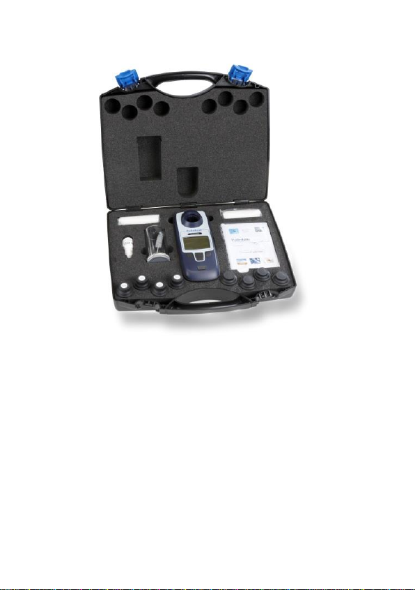
KITCONTENTS...............................................................................4
QUADOPTIX™ TECHNOLOGY....................................................5
START-UP........................................................................................6
Battery Life/Replacement...........................................7
SYSTEMMENU...............................................................................9
Log ..........................................................................9
Operator ID ..............................................................9
Sample ID ..............................................................10
Units......................................................................11
Language ...............................................................11
Set Time ................................................................11
Set Date................................................................. 11
Date Format ........................................................... 11
Version...................................................................11
Backlight ................................................................11
READINGMENU...........................................................................13
Taking Readings .....................................................14
Total Suspended Solids............................................16
CALIBRATIONMENU...................................................................17
Total Suspended Solids –Correlation ........................21
Total Suspended Solids –Factor ...............................22
Restore Factory Calibration ......................................23
CAREANDMAINTENANCE........................................................24
TROUBLESHOOTING..................................................................26
TECHNICALSUPPORT ANDWARRANTY...............................29
INST.32

3
INTRODUCTION
The Compact Turbimeter is the latest addition to the
Palintest Compact Meter range which includes
photometers for chlorine, ozone, chlorine dioxide and
ammonia.
The Turbimeter operates according to the ISO 7027
method for measurement of turbidity, utilising two NIR
light sources at 860nm as part of the QuadoptiX™
optical system.
The Turbimeter is provided in a hard case with
accessories and standards to support effective use of
the instrument.
For technical support or to report issues with this
product please contact Palintest or your supplier.

4
KIT CONTENTS
Compact Turbimeter Instrument (CT12 Model)
4 x Sample Cuvettes
4 x SDVB Calibration Standards
1 x Silicone Oil (10 ml)
2 x Packs of cleaning and polishing cloths
1 x Sample/Dilution Tube
1 x Cleaning Brush
2 x WP48 Heat Pads
Instructions

5
QUADOPTIX™ TECHNOLOGY
The Palintest Compact Turbimeter utilizes QuadoptiX™
technology for turbidity measurement –a sophisticated
optical approach designed to ensure turbidity measure-
ments are as accurate and repeatable as possible in
even the mostchallenging circumstances.
Turbidity measurements are carried out by analysis of
light scattered at 90° to the incident light (nephelometric
measurement) at levels below 40 NTU. Above 40 NTU
the recommendation is to measure also at 180° to
‘compensate’ the 90° readings.
QuadoptiX technology uses two independent sources
and two independent detectors to provide effectively
four entirely autonomous measurement systems in the
same instrument, allowing multiple validation of all
results for greater accuracy.

6
START-UP AND START PAGE
To switch the unit on, press the POWER button and
release. An audible beep will confirm the instrument is
on. Switch off by holding the POWER button for 1
second.
The LCD screen is provided with a backlight option that
can be set to on/off in the ‘System’menu (see Page 9).
The initial default setting is ON.
After initialization the Start page will appear and
display, initially defaulted to Mode screen and showing
three options:-
1 Reading –Select the mode to measure turbidity or
suspended solids (see Page 12).
2 Calibration –Choose either SDVB, Total Suspended
Solids or to Restore the factory calibration values (see
Page 16).
3 System –view or set Log (result and calibration),
Operator ID, Sample ID, Units, Language, Set
Time, Set Date, Date Format, Software Version and
switch the backlight on/off (see Page 9).
The option to change the Start page is available in the
‘System’ menu, allowing the user to choose to start in
the default mode above, normal measurement mode
or the last measurement mode used.
Navigation through Menus is carried out using the
Up/Down buttons, using the OK button to select or the
Back to return up a level.

7
Power
Back
OK
Up/Down
Sample Holder

8
Battery Life/Replacement
Your Compact Turbimeter is supplied with fresh batteries
that will be suitable for at least 150 hours of use.
Changing batteries is carried out through the
compartment on the rear of the instrument. Two ‘AA’
1.5V batteries are required. Current battery status is
displayed on the screen to assist in power management.
The Turbimeter has an auto-off function to save power,
automatically switching off the meter after five minutes
of inactivity.
A back-up battery is located on the PCB to store all
user data including the last mode used for reading.
Replacing the AA batteries will not lead to settings or
calibration data being lost.
If battery power is insufficient for effective analysis the
Turbimeter screen will show Error 110: Battery Low
and advise to change batteries. The battery icon will
also show ‘Empty’ status.
If battery power is insufficient for any operation the
Turbimeter screen will show Error 111: Battery
Critical and automatically shut down.

9
SYSTEM MENU
The System menu allows the user to set the Compact
Turbimeter preferences and review results and
calibration data.
Log
Select ‘Results’ or ‘Calibrations’.
Once the log has been chosen, select ‘View’or ‘Clear’.
The ‘Readings’log holds up to 100 data points with
date, time, Sample ID, Operator ID, Reading Mode and
Result. The oldest result will automatically be
overwritten when the log is full.
The ‘Calibrations’ log stores the date, time, method and
Operator ID (if set) for the last 12 good calibrations.
To view data select ‘View’ and use the up/down
buttons to scroll in either direction.
Use ‘Clear’ in either log to delete the entire log. Select
‘Clear’then ‘Yes’in the following screen to delete.
Operator ID
Optionally select or edit the username using
alphanumeric characters.
To create a new Operator ID select a blank line and
press ‘OK’
Press ‘New’to create the ID.
Use the Up/Down buttons to show/change characters.

10
When the correct character is shown, press and hold
the [+] keyfor one second to move to the next character.
Correct mistakes byholding the [Del] keyfor one second.
Complete the process by pressing ‘Done’briefly.
Select ‘OK’to accept the entry or Edit to modify the
entry.
To modify or delete an existing Operator ID, highlight
the ID and select ‘Edit’ Choose either ‘Edit’ to modify
the existing entry or ‘Delete’ to remove it from the list.
Deleting the Operator ID will not affect results stored in
the log.
Up to 12 Operator IDs can be stored and recalled from
memory as required.
To return to the System menu, either select the
Operator ID required using ‘OK’ or highlight a blank
entry (if one is available) and press ‘Back’
Sample ID
Optionally set the Sample ID using the same method
as Operator ID.
Up to 24 Sample IDs can be stored and recalled as
required.
Both Operator ID and Sample ID are stored in the log
with result and calibration data.

11
Units
Results can be displayed in NTU, FTU and FNU.
Language
Select English, French, German, Spanish or Italian
and press ‘OK’ to switch to alternative languages.
Set Time
Increase/decrease the time by using the Up/Down
buttons.
When the correct time is shown select ‘OK’.
Set Date
Increase/decrease the date by using the Up/Down
buttons.
When correct select ‘OK’.
Date Format
Select DD/MM/YYYYY or MM/DD/YYYY as required.
Version
The serial number of the instrument and the software
version will be displayed.
The instrument serial number is required for support
and warranty claim.
Backlight
Select either ‘Off’ or ‘On’ as required.

12
The Compact Turbimeter will maintain the current
status until changed.
Start Page
The ‘Start Page’ allows the user to define a choice of
initial screens/modes on powering the Compact
Turbimeter.
To change start page, highlight the favoured choice for
initial screen –Mode Menu, Normal Reading Mode or
Last Reading Mode. The new Start Page choice will
appear when the instrument is next powered on.
LCD Contrast
The default setting is appropriate for all but the most
challenging light conditions but, should it become
necessary, the contrast setting for the LCD screen can
be manually adjusted.
Use the up/down buttons to adjust the image on screen
until the alternating shapes are clearly visible and
press ‘Back’

13
READING MENU
When taking readings ensure the cuvette is free from
dirt, dust and condensation using the supplied lint-free
cloths.
Ensure the light cap is in place to prevent stray light
from adversely affecting readings. If no light cap is
fitted or the sample cuvette is not correctly inserted
Error 107: Blanking Error will be reported.
Microscopic scratches on the sample cuvette will
refract light and can lead to higher than expected
values. To prevent scratches having an impact apply a
thin film of silicone oil (provided) to the sample cuvette.
Select the ‘Reading’menu and choose from:-
Normal –This mode reads the turbidity of the sample
in approximately eight seconds with an audible beep at
the start and finish of measurement.
Average –Selecting this mode prompts a further choice
of Short Average (3 readings), Medium Average (6
readings) and Long Average (12 readings). Averaging
readings is extremely useful for turbidity measurement
where particles are in motion or where extremely high
accuracy is required.
Continuous-Capture –This mode allows continuous
reading of sample turbidity until measurement is
manually interrupted. This mode will support cuvette
indexingand settling studies on rapidly settling samples.

14
Total Suspended Solids –The relationship between
turbidity and suspended solids can be approximated
with correlated data. The QuadoptiX™ bench provides
the performance required to produce reliable data for
suspended solids, based on calculated factors (slope
andoffset) for turbidityversus suspended solids. Default
factorsare not possible due to the unique variety of size,
shape and reflectivity of individual sample matrices.
Calculated factors will provide a rapid qualitative value
for Total Suspended Solids that will be relevant until
process conditions change. This reading mode will
only become active upon a site-specific calibration
being stored in the Compact Turbimeter.
Taking Readings
Normal Mode
Choose ‘Reading’mode, select ‘Normal’and press ‘OK’.
Insert the sample with the orientation mark facing
forward and press ‘Read’.
A beep will sound at the start and end of measurement.
Result is displayed and stored in the results log with
date, time, Operator ID and Sample ID.
(NOTE: See the ‘System’section for details of the
result log).

15
Average Mode
Choose ‘Reading’mode, select ‘Average’and press
‘OK’.
Select the number of readings required for the
averaging function :-
Short Average –3 consecutive readings
Medium Average –6 consecutive readings
Long Average –12 consecutive readings
Insert the sample with the orientation mark facing
forward and press ‘Read’.
The instrument will beep at the start and end of
measurement cycle.
Result is displayed on the screen and stored in the log
with time, date, Operator ID and Sample ID.
Continuous-Capture Mode
Choose ‘Reading’mode, select ‘Continuous-Capture’
and press ‘OK’
Insert the sample with the orientation mark facing
forward and press ‘Read’.
A beep will occur at the start and end of each
measurement cycle.
To store data in the log, press ‘Capture’ (repeat as
required).

16
To cease measurement, press ‘Back’ at any time.
To index a cuvette, insert the sample cuvette with the
orientation mark facing forward.
Systematically rotate the sample cuvette 45° at a time
and record the position of the lowest value. This is the
optimal cuvette alignment for low turbiditymeasurement.
Total Suspended Solids
This mode will only be active if a site calibration has
been stored within the Turbimeter. Once a calibration
has been created (via the ‘Calibration’menu) the site
ID can be used to recall the site specific relationship
between turbidity and suspended solids.
Choose ‘Reading’mode, select ‘Total Suspended
Solids’and press ‘OK’.
Highlight the Site ID for the Site/Sample under
investigation using the Up/Down arrows. The calibration
data will be recalled automatically.
Insert the sample with the orientation mark facing
forward and press ‘Read’.
A beep will occur at the start and end of each
measurement cycle.
Result is displayed on the screen in mg/l and stored in
the log with time, date, Operator ID and Sample ID.

17
CALIBRATION MENU
The Compact Turbimeter is delivered with a stored
calibration carried out on primary Formazin standards
and validated as part of the production process. For
field use, a set of calibration standards are provided as
part of the kit.
Recalibration is only required if the standards provided
show an unacceptable level of variation from the stated
values on read-back.
Two different methods of calibration are available for
the Turbimeter.
The calibration methods are :-
SDVB –The use of SDVBfor field calibration of turbidity
meters is preferable due to the improved stability and
handling compared to Formazin. When calibrating
turbidity instruments SDVB standards are assigned to a
specific model and cannot be transferred. Using SDVB
standards from another manufacturer may differ greatly
when applied to the Turbimeter. This is normal behavior
and should not cause concern.
Formazin –freshly prepared standards can also be
used for calibration where available. Formazin is used
as the primary calibration material for the Turbimeter
and can also be used to align the calibration of different
instruments when discrepancies occur. Preparation of
Formazin standards from 4000 NTU stock solution is
required to be within the stated limits detailed below.

18
Total Suspended Solids –When using the Turbimeter
in Total Suspended Solids Reading mode, a calibration
is required to set the relationship between the measured
turbidity values and the ‘true’suspended solids value,
determined by gravimetric methods. This calibration can
either be an assigned series of values from the results
log or a simple algorithm with factors provided by the
user. This relationship is typically a straight line and
hence the factors consist of a slope and intercept.
The Compact Turbimeter has two methods of generating
the data for relating the measurement of turbidity to total
suspended solids (TSS):-
1 Correlation –Using the stored turbidity data from
the instrument log and relating it to manually
entered Total Suspended Solids data derived from
elsewhere. The minimum number of correlation
points required is one as the zero point can be used
as a second point. A maximum number of 50 data
points can be used.
2 Factor –Using data manipulated externally, a slope
and intercept for the straight line relationship can be
entered directly. Slope factors range from 0.1 –50.0
and intercepts can be set from -50.0 - +50.0

19
Calibrating the Compact Turbimeter
SDVB
Select Calibration and press ‘OK’.
Choose ‘SDVB’and press ‘OK’.
Select the lowest (0.05 –0.15) NTU standard and insert
into the sample chamber with the orientation mark
facing forward.
Use the Up/Down buttons to adjust the value on screen
to that on the standard and press ‘Read’.
Repeat the process for the 20 NTU, 100 NTU and 800
NTU standards.
If standards have expired, are inserted in incorrect
sequence or the 100 and 800 NTU standards are not
inverted prior to use Error 101: Incorrect Standard
may be shown.
After the final 800 NTU standard, the screen will show
‘Calculating…Please wait’ and a countdown will
appear to show time remaining.
On completion of the process the Compact Turbimeter
screen will show ‘Successful’.
Press ‘Back’ to leave the calibration process and return
to the Calibration menu.
To cease calibration during the data capture phase
press ‘Cancel’.
To cease the calibration process at any step, press
‘Back’ (calibration data will be discarded).

20
The time, date and Operator ID are stored in the
calibration log for GLP compliance (see Page 9,
System menu).
Formazin
Select Calibration and press ‘OK’.
Choose ‘Formazin’ and press ‘OK’.
Acceptable fresh Formazin standards should be
prepared within the following ranges:
Low Standard 0.01 –1.00 NTU
Second Standard 10.0 –30.0 NTU
Third Standard 90.0 –110.0 NTU
High Standard 720.0 –880.0 NTU
Select the lowest (0.01 –1.00) NTU standard and insert
into the sample chamber with the orientation mark
facing forward.
Use the Up/Down buttons to adjust the value on screen
to that on the standard and press ‘Read’.
Repeat the process for the second, third and high
standards.
After the final standard, the screen will show
‘Calculating…Please wait’ and a countdown will
appear to show time remaining.
On completion of the process the Compact Turbimeter
screen will show ‘Successful’.
Table of contents