Palmgren 9681109 User manual

Operating Manual & Parts List 9681109 & 9681108
6˝x 10˝& 6˝x 14˝
Belt & Disc Sanders
Read carefully and follow all safety rules and operating
instructions before first use of this product.
9644958.01-0220
Model 9681109
6"x10" Belt & Disc Sander
Model 9681108
6"x14" Belt & Disc Sander

2
Palmgren Operating Manual & Parts List 9681109 & 9681108
DESCRIPTION
Palmgren Model 9681109 6”x 10”Belt Disc Sander with stand and
Model 9681108 6”x 14”Belt Disc Sander with cabinet are con-
structed of rugged cast iron and heavy gauge steel providing sta-
bility and vibration-free operation.The belt disc sanders are used to
sand,deburr, bevel and grind large workpieces of wood, plastic and
metal.
The belt housing can be pivoted from vertical to horizontal for
sanding large,straight workpieces.The belt assembly includes a tilt-
ing cast iron table that tilts out 45º, miter gauge and 4” dust collec-
tion chute.
The 10” or 14” disc can be used to sand or bevel surfaces with the
use of a cast iron table that tilts out 45º and in 20º, miter gauge slot
and 4”dust collection chute.
The 3”diameter idler drum permits the sanding of contoured
shapes and finishes by positioning the adjustable platen from a
horizontal to vertical position.
The collection chutes accept the standard 4”dust collection hose
for quick removal of dust.The adjustable miter gauge can be used
on both the belt and disc tables for guiding the workpiece at a de-
sired angle while sanding.
UNPACKING
Refer to Figure 1.
Check for shipping damage.If damage has occurred, a claim must
be filed with carrier.Check for completeness. Immediately report
missing parts to dealer.
The sander comes assembled as one unit. Additional parts which
need to be fastened to sander, should be located and accounted
for before assembling.
A Abrasive Disc 100X
C Miter Gauge Assembly
D Workstop
F Intake Port Cap
• Parts Bag
Parts bag includes: one 8mm flat washer,four foot rest assemblies,
6mm hex wrench and 4mm long hex wrench.
SPECIFICATIONS
9681109, 6"x10" 9681108, 6"x14"
Belt Platen Area (W x L) 6-3/4" x 14-1/2" 6-3/4" x 14-1/2"
Belt Table Dim. (W x D) 8-5/8" x 6.0" 8-5/8" x 6.0"
Belt Table Tilts 45 degree 45 degree
Dust Chute Size 4" 4"
Belt Speed (SFPM-60 Hz) 2258 FPM 2258 FPM
Disc Diameter 10" (PSA) 14" (PSA)
Disc Table Dim (W x D) 11-1/4" x 7-1/4" 15-5/8" x 7-1/4"
Disc Table Tilt 45 degree 45 degree
Disc Speed (RPM) 1720 1720
Stand Dim (L x W x H) 24¾" x 19" x 21¼" N/A
Cabinet Dim (L x W x H) N/A 17½" x 20" x 28"
HP 1.0 HP 1.5 HP
Voltage 115/230 115/230
RPM 1720 1720
Phase 1 1
Amps 9.5/4.75 12.5/6.25
Assembled Wt. 141 lbs. 180 lbs.
Assembled Dim (L x W x H) 29.3"x18.3"x51.8" 30.7"x20"x51"
Shipping Weight 178.5 lbs. 236 lbs.
Shipping Dim (L x W x H) 30"x19"x34.8" 31.5"x22"x56.3"
SAFETY RULES
WARNING: For your own safety, read all of the instructions and
precautions before operating tool.
CAUTION: Always follow proper operating procedures as defined
in this manual even if you are familiar with use of this or similar
tools. Remember that being careless for even a fraction of a second
can result in severe personal injury.
WARNING: Some dust created by power sanding, sawing, grind-
ing, drilling and other construction activities contains chemicals
known to the state of California to cause cancer, birth defects or
other reproductive harm.
Some examples of these chemicals are:
•Lead from lead-based paints.
•Crystalline silica from bricks and cement and other
masonry products.
•Arsenic and chromium from chemically-treated lumber.
Your risk from these exposures vary, depending on how often you
do this type of work.To reduce your exposure to these chemicals:
work in a well ventilated area and work with approved safety
equipment. Always wear OSHA/NIOSH approved, properly fitting
face mask or respirator when using such tools.
BE PREPARED FOR JOB
•Wear proper apparel. Do not wear loose clothing, gloves, neck-
ties, rings, bracelets or other jewelry which may get caught in
moving parts of machine.
•Wear protective hair covering to contain long hair.
•Wear safety shoes with non-slip soles.
•Wear safety glasses complying with United States ANSI Z87.1.
Everyday glasses have only impact resistant lenses.They are
NOT safety glasses.
•Wear face mask or dust mask if operation is dusty.
•Be alert and think clearly.Never operate power tools when tired,
intoxicated or when taking medications that cause drowsiness.
Figure 1 – Unpacking sander.
D
A
B
EF
C

3
Palmgren Operating Manual & Parts List 9681109 & 9681108
SAFETY RULES (CONTINUED)
PREPARE WORK AREA FOR JOB
•Keep work area clean. Cluttered work areas and work benches
invite accidents.
•Do not use power tools in dangerous environments. Do not use
power tools in damp or wet locations. Do not expose power
tools to rain.
•Work area should be properly lighted.
•Proper electrical receptacle should be available for tool.
Three-prong plug should be plugged directly into properly
grounded, three-prong receptacle.
•Extension cords should have a grounding prong and the three
wires of the extension cord should be of the correct gauge.
•Keep visitors at a safe distance from work area.
•Keep children out of the workplace. Make workshop childproof.
Use padlocks, master switches or remove switch keys to prevent
any unauthorized use of power tools.
TOOL SHOULD BE MAINTAINED
•Always unplug tool prior to inspection.
•Consult manual for specific maintaining and adjusting proce-
dures.
•Keep tool lubricated and clean for safest operation.
•Remove adjusting tools. Form habit of checking to see that ad-
justing tools are removed before switching machine on.
•Keep all parts in working order. Check to determine that the
guard or other parts will operate properly and perform their in-
tended function.
•Check for damaged parts. Check for alignment of moving parts,
binding, breakage, mounting and any other condition that may
affect a tool’s operation.
•A guard or other part that is damaged should be properly re-
paired or replaced. Do not perform makeshift repairs. (Use the
parts list to order replacement parts.)
KNOW HOW TO USE TOOL
•Use right tool for job. Do not force tool or attachment to do a
job for which it was not designed.
•Disconnect tool from power when changing abrasive belt or
disc.
•Avoid accidental start-up.Make sure that the switch is in the
OFF position before plugging in.
•Do not force tool.It will work most efficiently at the rate for
which it was designed.
•Keep hands away from moving parts and sanding surfaces.
•Never leave tool running unattended.Turn the power off and do
not leave tool until it comes to a complete stop.
•Do not overreach.Keep proper footing and balance.
•Never stand on tool. Serious injury could occur if tool is tipped
or if belt or disc are unintentionally contacted.
•Know your tool. Learn the tool’s operation, application and
specific limitations.
•Handle workpiece correctly. Protect hands from possible injury.
•Turn machine off if it jams. Belt jams when it digs to deeply into
workpiece. (Motor force keeps it stuck in the work).
•Support workpiece with miter gauge, belt platen or work table.
•Maintain 1/16” maximum clearance between table and sanding
belt or disc.
CAUTION: Think safety! Safety is a combination of operator
common sense and alertness at all times when tool is being used.
ASSEMBLY
CAUTION: Do not attempt assembly if parts are missing.
Use this manual to order replacement parts.
Before sander is assembled, a suitable location should be chosen.
The sander with cabinet weighs approximately 200 lbs when com-
pletely assembled.They should be assembled on location.
•Sander needs to be set on a flat, level surface.
•Make sure there is ample room for moving the workpiece
through the entire cut.There must be enough room that nei-
ther the operator nor the bystanders will have to stand in line
while using the tool.
•Good lighting and correct power supply are also required for a
proper work area.
ADJUST BELT HOUSING TO VERTICAL POSITION
1. Move to the front of the sander; loosen and remove four knobs.
2. Remove dust hoods.
3. Loosen both hex nuts on the belt housing casting. Do not take
out hex nut.
4. Move to the rear of the sander and gently lift the belt housing
up supporting the housing from both sides.
5. Lift belt housing until it is adjusted to the vertical position.
6. Tighten both hex nuts from the rear of the sander.
7. Replace dust hood and tighten knobs.
ATTACH FOOT RESTS
Required parts and hardware: Four foot rest assemblies.
CAUTION: Sander with cabinet weighs approximately 200 lbs. At
least two people are required to attach foot rests.
1. Carefully tip the sander to raise cabinet from the floor just
enough so that one foot rest with bolt can be positioned under
the cabinet corner so that the bolt slides through the hole on
the cabinet base. Slowly set the sander back to the floor. Repeat
three more times to position one foot rest with bolt under each
of the cabinet corner.
2. Loosen knob and open cabinet door.
3. Using the cabinet door opening, secure foot rests to cabinet
using four flat washers and four hex nuts.
4. Make sure all the hex nuts are tight.
5. Close cabinet door and secure it with knob.

4
Palmgren Operating Manual & Parts List 9681109 & 9681108
ASSEMBLY (CONTINUED)
ATTACH BELT TABLE
Refer to Figure 2.
Required parts and hardware: Belt table with trunnion, handle, and
8mm flat washer.
1. Position belt table on the belt housing so that the trunnion
travels on the slide.
2. Set the belt table position so that the 0° mark on the trunnion is
aligned with the pointer.
3. Secure belt table position using the handle and flat washer.
Tighten handle into the threaded hole on the belt housing.
Sander is shipped with the belt tension handle at the released posi-
tion. Pull down the handle toward the belt table to tension the belt.
•Make sure that the clearance between the belt and belt table
does not exceed 1/16”.
•Wear protective glove and manually push the belt to verify that
belt travels smoothly and without interference.
POSITION DISC TABLE
Required part: Handle
1. Sander is shipped with the disc table attached to the disc guard
using a handle with flat washer one side and a hex head bolt
with flat washer on the other side.
2. Loosen and remove hex head bolt and flat washer from the disc
table.
3. Replace hex head bolt with the handle provided. Secure disc
table to disc guard using the handle and flat washer.
ATTACH ABRASIVE DISC TO CAST IRON DISC
Refer to Figures 3 and 4.
Sander is shipped with the abrasive not applied to the cast iron disc.
1. Clean the cast iron disc if necessary prior to applying the abrasive.
2. Remove the adhesive cover from the back of the abrasive disc.
3. Slide the abrasive between the disc table and cast iron disc and
center abrasive on the cast iron disc.
4. Apply pressure on abrasive to paste.
5. Make sure abrasive is pasted evenly on the cast iron disc.
6. Make sure that the clearance between disc table and abrasive
disc does not exceed 1/16”.
7. Use a straight edge or square to check if the disc table is at right
angle to the disc.
8. Wear a protective glove and manually turn the disc to verify
that the disc turns freely and without interference.
ATTACH MITER GAUGE
Required part: Miter gauge assembly
Miter gauge is shipped completely assembled and can be used
with the belt or disc tables.
• Slide miter gauge bar into the slot on belt or disc table.
INSTALLATION
Refer to Figures 5, 6 and 7.
WARNING: All electrical connections must be performed by a
qualified electrician.
POWER SOURCE
The motor is designed for operation on the voltage and frequency
specified.Normal loads will be handled safely on voltages not more
than 10% above or below the specified voltage.
Running the unit on voltages which are not within the range may
cause overheating and motor burnout.Heavy loads require that
voltage at motor terminals be no less than the voltage specified on
nameplate. Power supply to the motor is controlled by a single pole
locking rocker switch. Remove the key to prevent
unauthorized use.
GROUNDING INSTRUCTIONS
WARNING: Improper connection of equipment grounding con-
ductor can result in the risk of electrical shock. Equipment should
be grounded while in use to protect operator from electrical shock.
•Check with a qualified electrician if grounding instructions are
not understood or if in doubt as to whether the tool is properly
grounded.
•This tool is equipped with an approved 3-conductor cord rated
at 300V and a 3-prong grounding type plug (See Figure 5) for
your protection against shock hazards.
•Grounding plug should be plugged directly into a properly in-
stalled and grounded 3-prong grounding-type receptacle, as
shown (Figure 5).
Figure 2 – Attach belt table.
Belt Tension Handle
Table Lock Handle
Figure 3 – Attach abrasive disc.
Figure 4 - Check disc table.
Figure 5 – 3-Prong Receptacle
Properly Grounded Outlet
Grounding Prong
3-Prong Plug

5
Palmgren Operating Manual & Parts List 9681109 & 9681108
INSTALLATION (CONTINUED)
•Do not remove or alter grounding prong in any manner. In the
event of a malfunction or breakdown, grounding provides a
path of least resistance for electrical shock.
WARNING: Do not permit fingers to touch the terminals of plug
when installing or removing from outlet.
•Plug must be plugged into matching outlet that is properly in-
stalled and grounded in accordance with all local codes and or-
dinances. Do not modify plug provided. If it will not fit in outlet,
have proper outlet installed by a qualified electrician.
•Inspect tool cords periodically, and if damaged, have repaired
by an authorized service facility.
•Green (or green and yellow) conductor in cord is the grounding
wire. If repair or replacement of the electric cord or plug is nec-
essary, do not connect the green (or green and yellow) wire to a
live terminal.
•Where a 2-prong wall receptacle is encountered, it must be re-
placed with a properly grounded 3-prong receptacle installed
in accordance with National Electric Code and local codes and
ordinances.
WARNING: This work should be performed by a qualified
electrician.
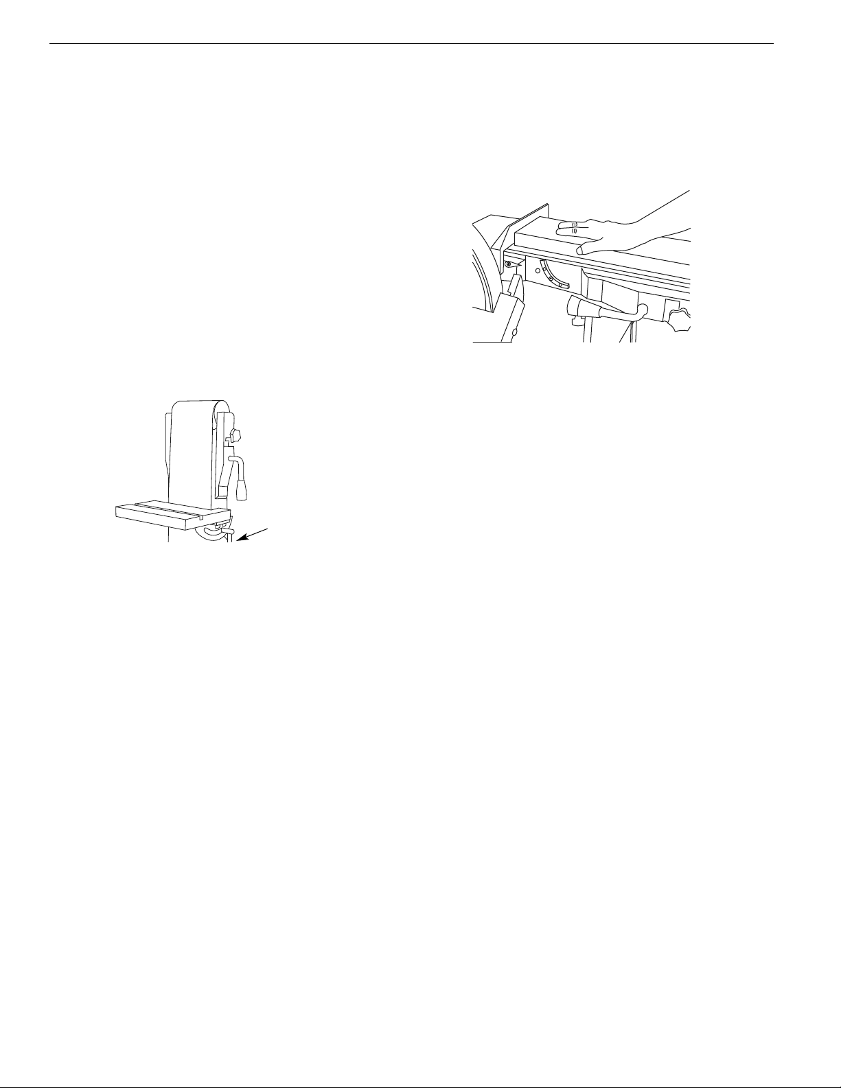
•A temporary 3-prong to 2-prong grounding adapter (See Figure
6) is available for connecting plugs to a two pole outlet if it is
properly grounded.
•Do not use a 3-prong to 2-prong grounding adapter unless per-
mitted by local and national codes and ordinances.
(A 3-prong to 2-prong grounding adapter is not permitted in
Canada.) Where permitted, the rigid green tab or terminal on
the side of the adapter must be securely connected to a perma-
nent electrical ground such as a properly grounded water pipe,
a properly grounded outlet box or a properly grounded wire
system.
•Many cover plate screws,water pipes and outlet boxes are not
properly grounded.To ensure proper ground, grounding means
must be tested by a qualified electrician.
EXTENSION CORDS
•The use of any extension cord will cause some drop in voltage
and loss of power.
•Wires of the extension cord must be of sufficient size to carry
the current and maintain adequate voltage.
•Running the unit on voltages which are not within ±10% of the
specified voltage may cause overheating and motor burn-out.
•Use the table to determine the minimum wire size (A.W.G.) ex-
tension cord.
•Use only 3-wire extension cords having 3-prong grounding
type plugs and 3-pole receptacles which accept the tool plug.
•If the extension cord is worn, cut or damaged in any way, re-
place it immediately.
ELECTRICAL CONNECTIONS
WARNING: All electrical connections must be performed by a
qualified electrician. Make sure tool is off and disconnected from
power source while motor is mounted, connected,reconnected or
anytime wiring is inspected.
•Motor and wires are installed as shown in wiring diagram (See
Figure 7). Motor is assembled with approved, 3-conductor cord
to be used at 120/240 volts.Motor is prewired at the factory for
120 volts.
Sander has a locking rocker switch with removable key for safe and
easy operation
•Remove the key from the locking rocker to prevent unautho-
rized use of the tool.To replace the key, press key into the slot
on the locking rocker.
•To use the sander witha 240V power supply, have a qualified
electrician rewire motor and attach a 240 volt three-prong plug
onto sander line cord.
Sander also has a thermal overload protector to prevent damage to
motor and other electrical components.The thermal overload pro-
tector will get activated when high temperature conditions are ob-
served while operating the tool.This will turn the tool off to
prevent temperature buildup. If that occurs, give adequate time for
the sander to cool down and depress the reset button once.The
tool will be ready to operate.
OPERATION
Refer to Figure 7.
WARNING: Operation of any power tool can result in foreign ob-
jects being thrown into eyes which can result in severe eye dam-
age. Always wear safety goggles complying with United States
ANSI Z87.1 (shown on package) before commencing power tool
operation.
CAUTION: Always observe the following safety precautions:
•Whenever adjusting or replacing any parts on the tool, turn
switch OFF and remove the plug from power source.
•Recheck table handles.They must be tightened securely.
•Make sure all guards are properly attached and securely
fastened.
•Make sure all moving parts are free and clear of any interference.
•Make sure all fasteners are tight and have not vibrated loose.
•With power disconnected, test operation by hand to verify
clearance and adjust if necessary.
•Always wear eye protection or face shield.
•Make sure abrasive belt tracks properly. Correct tracking gives
optimum performance.
•After turning switch ON, always allow belt to come up to full
speed before sanding or grinding.
•Be sure motor runs clockwise on disc side. Abrasive belt must
travel down.
•Keep your hands clear of abrasive belt, disc and all moving parts.
Figure 6 – 2-prong receptacle with adapter.
Grounding Lug
Adapter
3-Prong Plug
2-Prong Receptacle
Make sure this is
connected to a
known grounded
receptacle.
Volts
120 25 50 100 150
240 50 100 150 300
0 6 18 16 16 14
6 10 18 16 14 12
10 12 16 16 14 12
12 16 14 12
More Not
Than More Than Minimum Gage for Cord
Total Length of Cord in Feet
Not Recommended
Ampere Rating
Extension Cord Table

6
Palmgren Operating Manual & Parts List 9681109 & 9681108
OPERATION (CONTINUED)
•For optimum performance, do not stall motor or reduce speed.
Do not force the work into the abrasive.
•Support workpiece with belt table when sanding with belt, with
disc table when sanding with disc.
•Never push a sharp corner of workpiece rapidly against belt or
disc. Abrasive backing may tear.
•Replace abrasives when they become loaded (glazed) or frayed.
•When grinding metal, move workpiece across abrasive to
prevent heat build-up.
•Never attempt wet sanding. If workpiece becomes too hot to
handle, cool it in water.
POSITION BELT TABLE
Refer to Figure 7.
The belt table can be tilted from 0° (at right angle to the table) to
45°.To adjust belt table position:
1. Unlock the handle on the right side of table.
2. Set the belt table to any angle between 0° and 45° using the
scale.
2. Lock the handle to secure belt table position.
WORK STOP
The work stop can be used instead of the belt table.
1. Remove belt table from the belt housing by loosening and re-
moving handle.
2. Mount workstop using bolt and washer which are located on
belt housing.
ADJUSTING BELT HOUSING
The belt housing can be positioned at a full vertical position, a full
horizontal position, or at any angle in between which is convenient
for the sanding operation.
To adjust belt housing position:
1. Loosen and remove four knobs.
2. Remove dust hoods.
3. Loosen hex nuts.
4. Move to the rear of the sander.
5. Gently push belt housing to move to the desired angle.
•A positive stop bolt is provided to stop the belt housing at the
full horizontal position.
6. Tighten both hex nuts to secure belt housing position.
7. Replace dust hoods using the knobs.
HORIZONTAL BELT SANDING
Refer to Figure 8.
1. Adjust the belt housing to full horizontal position as described
in the above section,“Adjusting Belt Housing”.
2. Remove the belt table by removing handle.
3. Install work stop as described in“Work Stop”.
•Idler drum can be used as a contact drum to sand curved sur-
faces. (Removing belt guard will be required.)
ABRASIVE BELT FINISHING
•Finishing flat surfaces: Hold workpiece firmly with both hands;
keep fingers away from abrasive belt.
•Use work stop.Work stop is used to position and secure work
being sanded.Keep end butted against work stop and move
work evenly across abrasive belt. Use extra caution when finish-
ing very thin pieces.
•Finishing long pieces: remove work stop. Apply only enough
pressure to allow abrasive belt to remove material.
•Finishing curved edges: Finish outside curves on flat portion of
abrasive belt. Finish inside curves on idler drum portion of abra-
sive belt.
•Finishing end grain: It is more convenient to finish ends of long
workpieces with the abrasive belt in a vertical position.
•Move work evenly across the belt.
•For accuracy use miter gauge.
•Adjust belt table angle for beveled work.
USING MITER GAUGE
•The miter gauge is used on either the disc or belt table.Use the
miter gauge for securing the work and holding the proper
angle while sanding.
•Adjust angle by repositioning the miter gauge. Loosen the knob
to reposition miter gauge.
•Tighten the knob to secure miter gauge position.
•Miter gauge assembly has a positive stop set-up for 90° and 45°
on either side.
•To use the positive stop, loosen the knob, retract the indexing
pin, turn the miter gauge slightly, slide in indexing pin and turn
the miter gauge until the edge of the screw is stopped by the
indexing pin.
•Check accuracy of miter gauge scale.
•Use a combination square to adjust miter gauge square to disc.
Scale should be at zero. Loosen screw and reposition scale if
necessary.
Figure 7 - Attach belt table.
Table Lock Handle
Figure 8 - Horizontal belt sanding.

7
Palmgren Operating Manual & Parts List 9681109 & 9681108
OPERATION (CONTINUED)
BELT TRACKING
Belt should ride centered on drive and idler drums.The sander is
shipped with the tracking mechanism properly adjusted.However,
if adjustment is necessary:
1. Loosen knob on either side of belt housing.
2. Turn the unit on.
3. Insert a 1/8“ or 5/32“ hex wrench into the hole on adjusting nut
on either side.
4. Turn the adjusting nut to the right to move belt toward you or
turn the adjusting nut to the left to move belt away from you.
5. Make sure belt rides on the center of drive and idler drums.
6. Turn the unit off.
7. Tighten knobs on both sides of belt housing to secure tracking
adjustment.
REPLACING BELT
Sanding belt must be replaced when worn, torn, or glazed.
1. Push up the belt tension handle to release belt
tension.
2. Loosen knob securing belt guard.
3. Loosen and remove four knobs from the rear of the sander.
4. Remove belt cover.
5. Remove knob and bracket.
6. Slide old belt off the drive and idler drums.
NOTE: There may be an arrow on the inside of the belt.The arrow
should point down toward the belt table to ensure that the splice
in the belt will not come apart.
7. Slide new belt over the drive and idler drums; center belt on
drums.
8. Push the belt tension handle toward the drive drum to tension
belt.
9. Replace belt cover using knobs.
10. Replace belt guard and bracket.
11. Wear a protective glove and manually rotate the belt by hand to
check tracking. If tracking needs to be adjusted, follow steps de-
scribed in“Belt Tracking”.
12. Make sure belt rides centered on drive and idler drums.
POSITION DISC TABLE
Disc table is adjustable from 0° to 45° outward and 0° to 20° inward.
1. To adjust the disc table position, loosen the two handles from
either side of the disc table.
5. Use the scale on disc table trunnions to set table at the desired
angle.
3. Secure disc table position by tightening the two handles.
ABRASIVE DISC FINISHING
•Abrasive disc sanding is well suited for finishing small flat
surfaces and convex edges.
•Move workpiece across down side (left) of abrasive disc.
•Abrasive disc moves fastest and removes more material at outer
edge.
•For accuracy, use miter gauge.
REPLACING ABRASIVE DISC
1. Loosen and remove four bolts from disc cover plate.
2. Loosen two top bolts from dust collection port.
3. Remove disc cover plate.
4. Remove old abrasive by peeling it from the cast iron disc. Re-
moving cast iron disc is not necessary.
5. Clean cast iron disc if necessary. Select the proper abrasive disc
and apply to cast iron disc.
•Additional abrasive discs are available.
6. Replace disc cover plate.
7. Tighten bolts on dust collection port.
8. Replace four bolts to secure disc cover plate.
MAINTENANCE
WARNING: Make certain that the unit is disconnected from power
source before attempting to service or remove any component.
CLEANING
Keep machine and workshop clean. Do not allow sawdust to accu-
mulate on the tool. Keep the drums clean. Dirt on drums will cause
poor tracking and belt slippage. Operate tool with dust collector to
keep dust from accumulating.
WARNING: After sanding wood or nonmetallic material, always
clean dust collector and guards of sawdust before grinding metal.
Sparks could ignite debris and cause a fire.
•Be certain motor is kept clean and is frequently vacuumed free
of dust.
•Use soap and water to clean painted parts, rubber parts and
plastic guards.
LUBRICATION
The shielded ball bearings in this tool are permanently lubricated
at the factory.They require no further lubrication.
•When operation seems stiff, a light coat of paste wax applied to
the belt and disc tables will make it easier to feed the work
while finishing.
•Do not apply wax to the belt platen. Belt could pick up wax and
deposit it on the drums causing belt to slip.
KEEP TOOL IN REPAIR
•If power cord is worn, cut, or damaged in any way, have it re-
placed immediately.
•Replace worn abrasives when needed.
•Replace any damaged or missing parts. Use parts list to order
parts.
Any attempt to repair motor may create a hazard unless repair is
done by a qualified service technician.

8
Palmgren Operating Manual & Parts List 9681109 & 9681108
ELECTRICAL DIAGRAMS
Figure 9 - 9681109 single phase 115V electrical diagram.
Figure 10 - 9681109 single phase 230V electrical diagram.
9681109
Single Phase 115 V
9681109
Single Phase 230 V

9
Palmgren Operating Manual & Parts List 9681109 & 9681108
ELECTRICAL DIAGRAMS (CONTINUED)
Figure 11 - 9681108 single phase 115V electrical diagram.
Figure 12 - 9681108 single phase 230V electrical diagram.
9681108
Single Phase 115 V
9681108
Single Phase 230 V

TROUBLESHOOTING
10
Palmgren Operating Manual & Parts List 9681109 & 9681108
SYMPTOM POSSIBLE CAUSE(S) CORRECTIVE ACTION
Motor will not start
Motor will not start; fuses blown or
circuit breakers tripped
Motor fails to develop full power
(power output of motor decreases
rapidly with decrease in voltage at
motor terminals)
Motor overheats
Motor stalls (resulting in blown fuses
or tripped circuit breakers)
Machine slows down while operating
Abrasive belt runs off top wheel
1. Low voltage
2. Open circuit in motor or loose connections
1. Short circuit in line cord or plug
2. Short circuit in motor or loose connections
3. Incorrect fuses or circuit breakers in power
line
1. Power line overloaded with lights, appli-
ances and other motors
2. Undersized wires or circuits too long
3. General overloading of power company’s
facilities
Motor overloaded
1. Short circuit in motor or loose connections
2. Low voltage
3. Incorrect fuses or circuit breakers in
power line
4. Motor overloaded
Applying too much pressure to workpiece
Not tracking properly
1. Check power line for proper voltage
2. Inspect all lead connections on motor for loose or
open connection
1. Insect line cord or plug for damaged insulation and
shorted wires
2. Inspect all lead connections on motor for loose or
shorted terminals or worn insulation on wires.
3. Install correct fuses or circuit breakers
1. Reduce load on power line
2. Increase wire sizes, or reduce length of wiring
3. Request a voltage check from power company
Reduce load on motor.
1. Inspect connections in motor for loose or shorted
terminals or worn insulation on lead wires
2. Correct the low line voltage conditions
3. Install correct fuses or circuit breakers
4. Reduce load on motor
Ease up on pressure
See operation“Belt Tracking”

NOTES
11
Palmgren Operating Manual & Parts List 9681109 & 9681108

12
Palmgren Operating Manual & Parts List 9681109 & 9681108
Figure 13 – Repair Parts Illustration for 9681109 Belt

1 Universal Handle M6*1.0P*20L 50114028 2
2 Flat Washer 1/4"*25*2t * 3
3 Belt Table Support - Left 42031017 1
4 Flat Washer 8.5*20*1.5t * 8
5 Cap Screw M8*1.25P*12L * 4
6 Cap Screw M5*0.8P*12L * 6
7 Spring Washer M5 * 5
8 Trunnion 42031020 2
9 Trunnion Plate 42031005 2
10 Belt Table Support - Right 42031016 1
11 Belt Table 42031015 1
12 Cap Screw 1/4"-20UNC*3/8"L * 4
13 Lock Handle 42011044 1
14 Roll Pin 3*20L * 1
15 Flat Washer 12*23*2t * 2
16 Disc Spring 42011043 1
17 Micro-Adjusting Seat 42011039 1
18 Spring 42011041 1
19 Adjusting Knob 42011042 1
20 Flat Washer 3/8"*19*1t 50351073 1
21 Screw * 1
22 Shaft of Support Bracket 42011073 1
23 Nylon Nut 1/4"-20UNC 50252023 1
24 Spring 42011037 1
25 Eccentric Handle 42011038 1
26 Cap Screw 1/4"-20UNC*1 1/4"L * 1
27 Nylon Nut M6*1.0P * 1
28 Roll Pin 4*20L * 1
29 Shaft 42011046 1
30 Support Bracket 42011036 1
31 Nylon Nut 3/8"-24UNF (7t) * 1
32 Flat Washer 10.5*16*1.5 * 1
33 C-Ring STW-11 * 2
34 Ball Bearing 6201-2RS- * 2
35 Follow Roller 42011045 1
36 Bushing 42011048 1
37 Flat Washer 10*22*2t * 1
38 Nylon Nut 3/8"-16UNC (7t) * 1
39 Knub M6*1.0P*15L 50111025 1
40 Flat Washer 6.5*19*2t * 3
41 Hex. Screw M6*1.0P*12L * 4
42 Drive Drum Cover 42031022 1
43 Dust Chute 42031021 1
44 Air Controller 42031018 1
45 Sanding Belt TR332#100 9600511.00 1
46 Graphite Pad 42011057 1
47 Belt Support 42031028 1
48 Nylon Nut * 1
49 Drive Drum 42011027 1
50 Cap Screw M8*1.25P*16L * 4
51 Spring Washer M8 * 4
52 Handwheel Handle 34013101 1
53 Bracket 42031023 1
54 Hex. Nut M8*1.25P * 2
55 Leveling Pad 31041023 1
56 Set Screw M8*1.25P*10L * 4
57 Eccentric Bottom Bracket 42031004 1
58 Cap Screw M5*0.8P*18L * 1
59 Cap Screw M6*1.0P*12L * 1
60 Flat Washer 5.2*16*1t * 10
61 Safety Guard 42031007 1
62 Stop Plate 42031019 1
63 Cap Screw M6*1.0P*16L * 2
64 Cap Screw M8*1.25P*30L * 1
65 Hex. Screw M8*1.25P*45L * 1
66 Round Head Screw M5*0.8P*8L * 2
67 Upper Cover 42031006 1
68 Back Cover 42031025 1
69 Cap Screw M5*0.8P*8L * 4
70 Spring Washer 1/4” * 1
Ref.
No. Description Part No. Qty.
Ref.
No. Description Part No. Qty.
13
Palmgren Operating Manual & Parts List 9681109 & 9681108
REPAIR PARTS LIST FOR 9681109 BELT
(Δ) Not shown.
(N/A) Not available as repair part.
(*) Standard hardware item, available locally.

14
Palmgren Operating Manual & Parts List 9681109 & 9681108
Figure 14 – Repair Parts Illustration for 9681109 Disc

1 Key 5*5*70L 50604026 1
2 Motor 42031501 1
3 Hex. Screw M8*1.25P*20L * 7
4 Flat Washer 8.5*20*1.5t 50301091 8
5 Strain Relief PG 13.5 51104008 1
6 Key 5*5*25L 50604010 1
7 Spring Washer M8 * 3
8 Flat Washer 8.5*16*1.5t * 9
9 Flange 42031011 1
10 10" Disc 42031010 1
11 Set Screw M8*1.25P*6L * 2
12 Clamp Block 42031030 1
13 Cap Screw M6*1.0P*14L * 1
14 10" Sanding Disc TJ32#80 9636134.00 1
15 End Cover 42031009 1
16 Round Head Hex Screw M8*1.25P*45L * 2
17 Front Motor Guard 42031033 1
18 Rear Motor Guard 42031034 1
19 Cap Screw M6*1.0P*12L * 4
20 Flat Washer 6*12*1t * 8
21 Flat Washer 5.1*12*1t * 2
22 Round Head Screw M5*0.8P*10L * 2
23 Disc Guard 42031014 1
24 Lock Knob M5*0.8P*7L 50111019 2
25 Flat Washer 5.2*16*1t * 2
26 Front Disc Guard 42031036 1
27 Universal handle M6*1.0P*20L 50114028 2
28 Flat Washer 1/4"*25*2t * 2
29 Cap Screw M5*0.8P*12L * 4
30 Spring Washer M5 * 6
31 Trunnion 42031020 2
32 Trunnion Plate 42031005 2
33 Round Head Hex Screw M6*1.0P*12L * 8
34 Cap Screw M8*1.25P*16L * 4
35 Guard Fixed Seat - Left 42031026 1
36 Disc Table 42031001 1
37 Disc Table Support - Left 42031003 1
38 Round Head Screw M8*1.25P*12L * 4
39 Guard Fixed Seat - Right 42031027 1
40 Eccentric Bottom Bracket 42031004 2
41 Cap Screw M5*0.8P*18L * 2
42 Bushing 42031032 1
43 Point 42031012 1
44 Round Head Screw M5*0.8P*12L * 1
45 Angle Label 42031013 1
46 Disc Table Support - Right 42031002 1
47 Miter Gauge 42011201 1
Ref.
No. Description Part No. Qty.
Ref.
No. Description Part No. Qty.
15
Palmgren Operating Manual & Parts List 9681109 & 9681108
REPAIR PARTS LIST FOR 9681109 DISC
(Δ) Not shown.
(N/A) Not available as repair part.
(*) Standard hardware item, available locally.

REPLACEMENT PARTS LIST FOR 9681109 BASE
1Switch 42011601 1
2Round Head Screw M5*0.8P*10L *8
3Flat Washer 5.1*12*1t *2
4Switch Plate 42031024 1
5Overload 125V/250V 12A 42031601 1
6Tooth Washer M5 *4
7ID Label 38100305 1
8Base 42031008 1
9Magnet 18061018 1
10 Rubber Plug 34011029 1
11 Strain Relief 51101003 3
12 Motor Cord 42031701 1
13 Power Cord 42031801 1
14 Switch Cord 37071901 1
Ref.
No. Description Part Number Qty.
4203-B2
16
Palmgren Operating Manual & Parts List 9681109 & 9681108
Figure 15 – Replacement Parts Illustration for 9681109 Base
(Δ)Not shown.
(N/A)Not available as repair part.
(*) Standard hardware item, available locally.

17
Palmgren Operating Manual & Parts List 9681109 & 9681108
REPLACEMENT PARTS LIST FOR 9681109 STAND
1Stand Leg 42033001 4
2Stand Top - Long 42033002 2
3Long Rail 42033005 2
4Stand Top - Short 42033003 2
5Short Rail 42033004 2
6Carriage Bolt 5/16"-18UNC*1/2"L(7.9*1.7) *24
7Luck Nut w/Flange 5/16"-18UNC *24
8Hex. Nut M8*1.25P *4
9Leveling Pad 31041023 4
10 Flat Washer 8.5*20*1.5t *8
11 Hex. Screw M8*1.25P*16L *4
Ref.
No. Description Part Number Qty.
4203-B3
Figure 16 – Replacement Parts Illustration for 9681109 Stand
(Δ)Not shown.
(N/A)Not available as repair part.
(*) Standard hardware item, available locally.

18
Palmgren Operating Manual & Parts List 9681109 & 9681108
Figure 17 – Repair Parts Illustration for 9681108 Belt

1 Universal Handle M6*1.0P*20L 50114028 2
2 Flat Washer 1/4"*25*2t * 3
3 Belt Table Support - Left 42031017 1
4 Flat Washer 8.5*20*1.5t * 8
5 Cap Screw M8*1.25P*12L * 4
6 Cap Screw M5*0.8P*12L * 6
7 Spring Washer M5 * 5
8 Trunnion 42031020 2
9 Trunnion Plate 42031005 2
10 Belt Table Support - Right 42031016 1
11 Belt Table 42031015 1
12 Cap Screw 1/4"-20UNC*3/8"L * 4
13 Lock Handle 42011044 1
14 Roll Pin 3*20L * 1
15 Flat Washer 12*23*2t * 2
16 Disc Spring 42011043 1
17 Micro-Adjusting Seat 42011039 1
18 Spring 42011041 1
19 Adjusting Knob 42011042 1
20 Flat Washer 3/8"*19*1t * 1
21 Screw * 1
22 Shaft of Support Bracket 42011073 1
23 Nylon Nut 1/4"-20UNC * 1
24 Spring 42011037 1
25 Eccentric Handle 42011038 1
26 Cap Screw 1/4"-20UNC*1 1/4"L * 1
27 Nylon Nut M6*1.0P * 1
28 Roll Pin 4*20L * 1
29 Shaft 42011046 1
30 Support Bracket 42011036 1
31 Nylon Nut 3/8"-24UNF (7t) * 1
32 Flat Washer 10.5*16*1.5 * 1
33 C-Ring STW-11 * 2
34 Ball Bearing 6201-2RS 50501009 2
35 Follow Roller 42011045 1
36 Bushing 42011048 1
37 Flat Washer 10*22*2t * 1
38 Nylon Nut 3/8"-16UNC (7t) * 1
39 Knub M6*1.0P*15L 50111025 1
40 Flat Washer 6.5*19*2t * 3
41 Hex. Screw M6*1.0P*12L * 4
42 Drive Drum Cover 42031022 1
43 Dust Chute 42031021 1
44 Air Controller 42031018 1
45 Sanding Belt TR332#100 42031031 1
46 Graphite Pad 42011057 1
47 Belt Support 42031028 1
48 Nylon Nut * 1
49 Drive Drum 42011027 1
50 Cap Screw M8*1.25P*16L * 4
51 Spring Washer M8 * 4
52 Handwheel Handle 34013101 1
53 Bracket 42031023 1
54 Hex. Nut M8*1.25P * 2
55 Leveling Pad 31041023 1
56 Set Screw M8*1.25P*10L * 4
57 Eccentric Bottom Bracket 42031004 1
58 Cap Screw M5*0.8P*18L * 1
59 Cap Screw M6*1.0P*12L * 1
60 Flat Washer 5.2*16*1t * 10
61 Safety Guard 42031007 1
62 Stop Plate 42031019 1
63 Cap Screw M6*1.0P*16L * 2
64 Cap Screw M8*1.25P*30L * 1
65 Hex. Screw M8*1.25P*45L * 1
66 Round Head Screw M5*0.8P*8L * 2
67 Upper Cover 42031006 1
68 Back Cover 42031025 1
69 Cap Screw M5*0.8P*8L * 4
70 Spring Washer 1/4” * 1
Ref.
No. Description Part No. Qty.
Ref.
No. Description Part No. Qty.
19
Palmgren Operating Manual & Parts List 9681109 & 9681108
REPAIR PARTS LIST FOR 9681108 BELT
(Δ) Not shown.
(N/A) Not available as repair part.
(*) Standard hardware item, available locally.

20
Palmgren Operating Manual & Parts List 9681109 & 9681108
Figure 18 – Repair Parts Illustration for 9681108 Disc
This manual suits for next models
1
Table of contents
Other Palmgren Sander manuals
Popular Sander manuals by other brands

Rikon Power Tools
Rikon Power Tools 50-122 Operator's manual

EINHELL
EINHELL TE-OS 240 Original operating instructions

Makita
Makita SA5040C instruction manual

Defort
Defort 98291506 user manual

Wilton
Wilton 41002 Operating instructions and parts manual

Chicago Pneumatic
Chicago Pneumatic CP7255E-3 Operator's manual