Key Features
Voltage Regulation
Regulates the output voltage on Banks 1-4 to
120 VAC ± 5 VAC. This is accomplished
through two boost stages and one buck stage
of voltage regulation. In Boost Stage 1 the
voltage is boosted in the 109-119V range,
while Boost Stage 2 boosts the voltage in the
100-109V range. The Buck Stage acts to
reduce voltage in the 125-136V range.
LiFT Technology EMI/RFI Noise Filtration :
Your audio/video components are constantly
being bombarded by electromagnetic interfer-
ence (EMI) and radio frequency interference
(RFI) through their AC power source. This
contaminated power can affect audio/video
equipment and will degrade the overall per-
formance of your entire system. Common
symptoms of contaminated power include
loss of picture detail, dull colors, pops, hiss-
es, hums and visual artifacts.
Automatic Over & Under Voltage Protection
(AVM):
Panamax's patent pending power monitoring
circuitry constantly monitors the AC line volt-
age for unsafe voltage conditions such as
momentary spikes or prolonged over-volt-
ages and under-voltages (brownouts). These
unsafe conditions pose a very dangerous
threat to all electronic equipment within the
home. If the MAX® 5400-PM senses an
unsafe power condition, it will automatically
disconnect your equipment from the power to
protect equipment from damage.Once the
voltage returns to a safe level, the M5400-PM
will automatically reconnect the power.
• When subjected to a 6,000V (open circuit
voltage) / 500A (short circuit current) surge,
the M5400-PM limits its voltage output to
less than 330V peak, UL's best rating.
• If the magnitude of the surge is greater than
the capacity of the surge protection compo-
nents, the M5400-PM's Protect or Disconnect
Circuitry will disconnect your equipment in
order to protect it. The M5400-PM will need
to be repaired or replaced by Panamax if this
occurs within the product’s 3 year warranty.
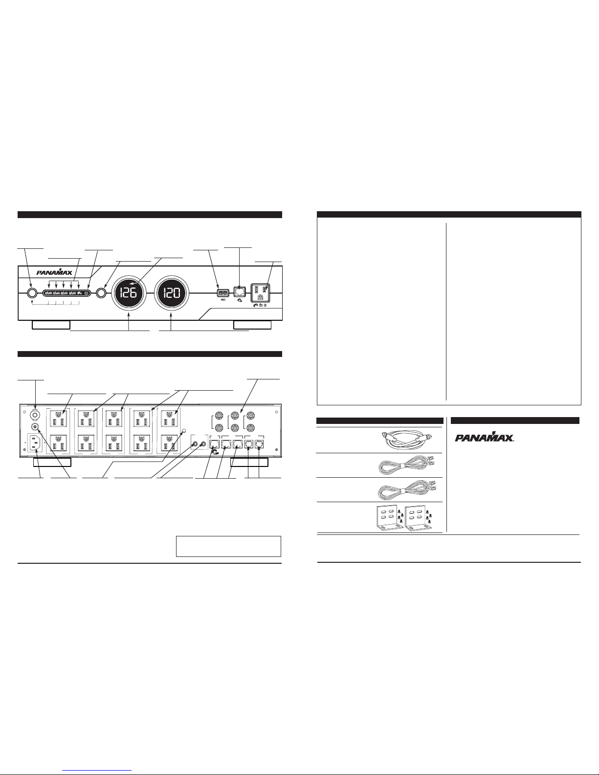
5 Isolated Outlet Banks
The M5400-PM is designed to provide noise
isolation between the outlet banks so that any
noise created by A/V components plugged
into the M5400-PM cannot contaminate the
power going to equipment plugged into the
other outlet banks of the M5400-PM.
Sequential Startup/Shutdown:
Complex audio/video systems may be sus-
ceptible to voltage transients generated inter-
nally at start-up/shutdown if all of the equip-
ment is powered on or off at the same time.
This can cause speaker “thumps” which are
not only annoying but can also damage the
speakers and/or trip product circuit breakers.
The M5400-PM is designed to eliminate these
transients by providing a “start-up” delay for
the High-Current outlets and a “shutdown”
delay for the Switched Outlet Banks. This
minimizes in-rush current issues by allowing
the components plugged into the Switched
Outlet Banks to power-up and stabilize before
any amplifiers and powered sub-woofers are
turned on. This sequence is reversed during
shutdown. The amplifiers and powered sub-
woofers turn off, their power supplies drain,
and then the equipment plugged into the
Switched Outlet Banks are turned off.
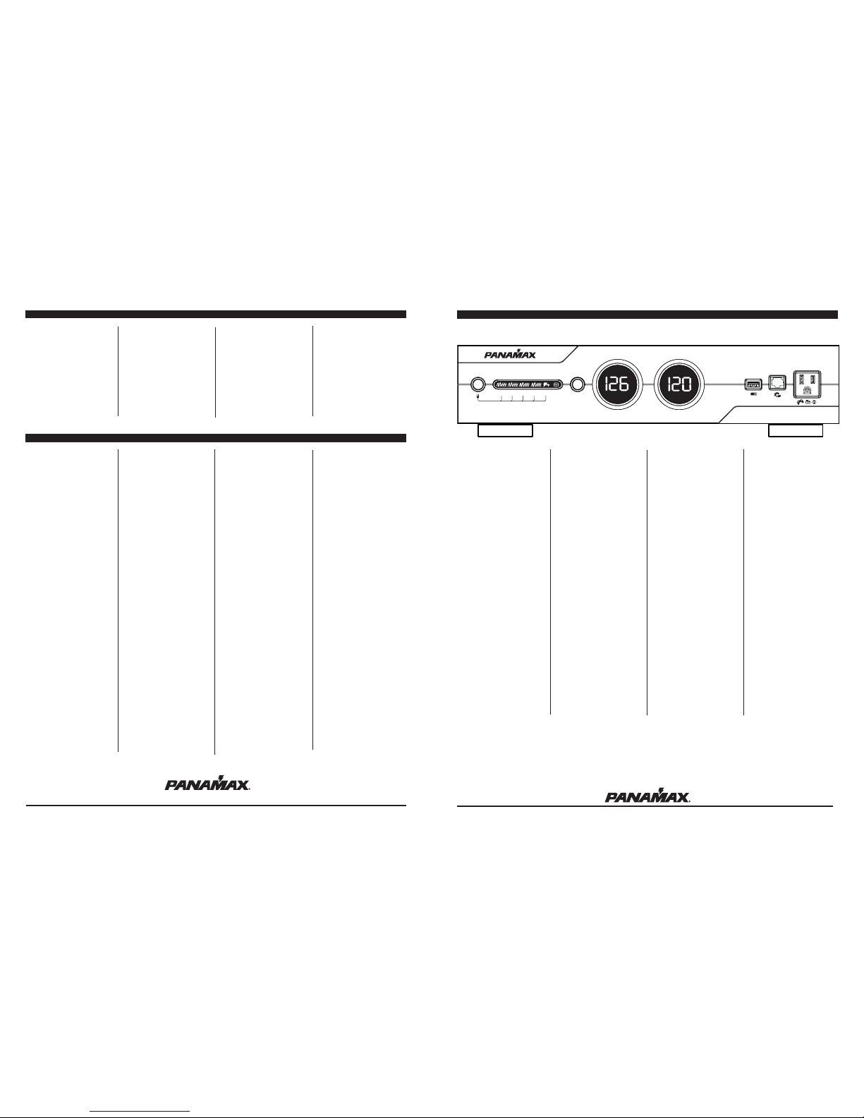
USB Charger:
The M5400-PM features a front panel con-
venience charger for mp3 players, cell
phones, video game controllers, and other
small electronics. NOTE: Some devices may
not be compatible with this USB charger.
Gaming LAN Port:
The M5400-PM features an easy-to-access
LAN port pass-thru from the rear panel to the
front panel. Perfect for online gaming.
Gaming Outlet:
The M5400-PM features a convenience outlet
located on the front panel. Perfect for gaming
systems and other electronics. 120VAC ±
6VAC
Voltage Sense Trigger: The M5400-PM volt-
age sense trigger input uses a standard
3.5mm (1/8") mini-mono plug.
This feature provides an ON/OFF trigger for
the M5400-PM using a Direct Current voltage
signal. Many components such as pre-ampli-
fiers and receivers have a DC trigger built in,
and will transmit a constant power signal
when turned on and in use. The presence of
this power signal will turn on the M5400-
PM's switched outlets. When the source com-
ponent is turned off, the voltage trigger signal
is also turned off and the M5400-PM's shut-
down sequence is initiated. An AC Adapter of
the appropriate voltage plugged into a
switched outlet may also be used if a DC trig-
ger is not built in.
Cable/Satellite/Antenna TV signal protec-
tion
Coaxial protection circuits achieve optimum
signal quality from our new coaxial protectors
that have the smallest signal loss on the mar-
ket - less than 0.5 db of attenuation from 0
MHz to 2.2 GHz. Our upgraded coaxial pro-
tection has been specifically designed to vir-
tually eliminate signal loss. The clamping
level of 75V will meet the demands of both
cable and satellite voltage while minimizing
exposure to damaging spikes and surges.
Telephone Line Protection:
Digital video recorders and satellite TV
receivers require a telephone line connection
for TV show scheduling and/or Pay-Per-View
services. The M5400-PM also provides surge
protection for this line. One pair of RJ-11 tele-
phone jacks is provided for this. The circuitry
utilizes auto-resetting PTCRs and solidstate
SIDACtors for reliability and unsurpassed
protection. The clamping level of the M5400-
PM's telephone protector is 260 volts. This
will allow typical ring voltage (90-130VAC)
and operating battery voltage (-48DC) to pass
through the circuit and still protect the
modem in your satellite receiver from dam-
age.
LAN Protection:
Protection circuits for 10/100 baseT Ethernet
lines. Incoming LAN line MUST be plugged
into the LINE jack. Patch cord to the equip-
ment MUST be plugged into the EQUIP jacks.
1 LAN jack goes to the front panel output jack.
8 wire protection, 52V clamping.
Model: M5400-PM
INS00815_E Rev. B 7/07 1
Panamax warrants to the purchaser of this
Panamax audio/video component style power
conditioner, for a period of three (3) years
from the date of purchase, that the unit shall
be free of defects in design, material or work-
manship, and Panamax will repair or replace
any defective unit. For product replacement
see "NOTIFICATION" below.
CAUTION
Audio/Video, computer and/or telephone sys-
tem installations can be very complex sys-
tems, consisting of many interconnected
components.
Due to the nature of electricity and surges, a
single protector may not be able to complete-
ly protect complex installations. In those
cases, a systemic approach using multiple
protectors must be employed. Systemic pro-
tection requires professional design. AC
power, satellite cables, CATV cables, tele-
phone/network lines or any other signal lines
entering the system that do not pass through
this surge protector may render the Panamax
Connected Equipment Protection Policy null
and void. For additional information on how
to protect your system, please contact
Panamax before connecting your equipment
to the surge protector.
WARNING NOTICE
Panamax products purchased through the
Internet do not carry a valid Product Warranty
or Connected Equipment Protection Policy
unless purchased from an Authorized
Panamax Internet Dealer and the original fac-
tory serial numbers are intact (they must not
have been removed, defaced or replaced in
any way). Authorized Panamax Internet
Dealers have sufficient expertise to insure
warranty compliant installations. For a list of
Authorized Panamax Internet Dealers go to
www.panamax.com
More detailed information is available at
www.panamax.com
If you have any questions regarding these
requirements, please contact Panamax
Customer Relations
Valid only in the United States and Canada.
It is the policy of Panamax that it will, at its elec-
tion, either replace, pay to replace at fair market
value, or pay to repair, up to the dollar amount
specified below, equipment that is damaged by
an AC power, cable, telephone, or lightning surge
while connected to a properly installed Panamax
power conditioner. Panamax must determine that
the power conditioner shows signs of surge
damage or is operating outside of design specifi-
cations, relative to its surge protection capability,
and under all of the circumstances failed to pro-
tect your connected equipment.
M4300-PM: $5,000,000
M5100-PM: $5,000,000
M5300-PM: $5,000,000
M5400-PM: $5,000,000
M4300-EX: $5,000,000
M5300-EX: $5,000,000
M5510-Pro: $5,000,000
M4310: $5,000,000
M5400-EX: $5,000,000
ML4200: $5,000,000
M4400: $5,000,000
M5410: $5,000,000
M5100-EX: $5,000,000
M5500-EX: $5,000,000
THIS WARRANTY IS SUBJECT TO THE FOLLOWING
CONDITIONS:
1. ORIGINAL OWNERSHIP REQUIREMENT:
Panamax's connected equipment policy extends
to the original purchaser of the Panamax product
only and is non-transferable. Original purchase
receipts must accompany any product return or
claim for connected equipment damage.
2. PROPER INSTALLATION: Panamax AC protec-
tors must be directly plugged into a properly
grounded 3-wire AC outlet. Extension cords*,
non-grounded two prong adapters, or other non-
Panamax surge products must not be used.
Building wiring and other connections to protect-
ed equipment must conform to applicable codes
(NEC or CEC). No other ground wires or ground
connections may be used. All wires (including,
e.g., AC power lines, telephone lines, signal/data
lines, coaxial cable, antenna lead-ins) leading into
the protected equipment must first pass through
a single Panamax protector designed for the par-
ticular application. The protector and the equip-
ment to be protected must be indoors in a dry
location, and in the same building. Panamax
installation instructions and diagrams must be
followed
3. NOTIFICATION: You must notify Panamax
within ten days of any event precipitating request
for product replacement or payment for connect-
ed equipment damage. A return authorization
(RA) number must first be obtained from the
Panamax Customer Relations Department at
www.panamax.com** before returning the pro-
tector Panamax. At this time, you must notify
Panamax if you believe you have a claim for dam-
aged connected equipment. Once you obtain an
RA number, please mark the number on the bot-
tom of the unit and pack it in a shipping car-
ton/box with enough packing material to protect
it during transit. The RA number must also be
clearly marked on the outside of the carton. Ship
the unit Panamax. Please note that you are
responsible for any and all charges related to
shipping the unit to Panamax. If connected
equipment damage was indicated on your RA
request, Panamax will mail you claim kit to be
completed and returned within 30 days. A con-
nection diagram of your system will be required
as part of the claim kit. Be sure to note its con-
figuration before disconnecting your equipment.
4. DETERMINATION OF FAILURE: Panamax will
evaluate the protector for surge damage. The
Panamax protector must show signs of surge
damage or must be performing outside (>10%)
of design specifications relative to its surge pro-
tection capability. Opening the enclosure, tam-
pering with, or modifying the unit in any way
shall be grounds for an automatic denial your
request for payment. Panamax, after evaluating
all information provided, shall determine whether
or not your request is eligible for payment. If the
surge protector shows no signs of AC power or
signal line surge damage and is working within
design specifications, Panamax will return the
unit to you with a letter explaining the test results
and notifying you of the rejection your claim.
Exceptions: If a dealer or installer replaces the
protector for the customer, replacement will be
returned to the dealer installer; or if the protector
is a pre-1996 model, it will be replaced; or, for a
Canadian customer, the protector will be
replaced. Panamax reserves the right to inspect
the damaged connected equipment, parts, or cir-
cuit boards. Please note that you are responsible
for any and all charges related to shipping the
damaged equipment to Panamax. Panamax also
reserves the right to inspect the customer's facil-
ity. Damaged equipment deemed uneconomical
to repair must remain available for inspection by
Panamax until the claim is finalized.
5. REQUEST PAYMENTS: Once Panamax has
determined that you are entitled to compensa-
tion, Panamax will, at its election, either pay you
the present fair market value of the damaged
equipment, or pay for the cost of the repair, or
send you replacement equipment, or pay the
equivalence of replacement equipment.
6. OTHER INSURANCE/WARRANTIES: This cov-
erage is secondary to any existing manufactur-
er's warranty, implied or expressed, or any insur-
ance and/or service contract that may cover the
loss.
6. OTHER INSURANCE/WARRANTIES: This cover-
age is secondary to any existing manufacturer's
warranty, implied or expressed, or any insurance
and/or service contract that may cover the loss.
7. EXCLUSIONS: THE PANAMAX CONNECTED
EQUIPMENT PROTECTION POLICY DOES NOT
APPLY TO: Service charges, installation costs,
reinstallation costs; setup cost; diagnostic
charges; periodic checkups; routine mainte-
nance; loss of use of the product; costs or
expenses arising out of reprogramming or loss of
programming and/or data; shipping charges or
fees; service calls; loss or damage occasioned by
fire, theft, flood, wind, accident, abuse or misuse,
and products subject to manufacturer's recall or
similar event.
8. DISPUTE RESOLUTION: Any controversy or
claim arising out of or relating to Panamax's
Connected Equipment Protection Policy, or the
alleged breach thereof, shall be settled by arbitra-
tion administered by the American Arbitration
Association under its Commercial Arbitration
Rules. You may file for arbitration at any AAA
location in the United States upon the payment of
the applicable filing fee. The arbitration will be
conducted before a single arbitrator, and will be
limited solely to the dispute or controversy
between you and Panamax. The arbitration shall
be held in any mutually agreed upon location in
person, by telephone, or online. Any decision
rendered in such arbitration proceedings will be
final and binding on each of the parties, and judg-
ment may be entered thereon in a court of com-
petent jurisdiction. The arbitrator shall not award
either party special, exemplary, consequential,
punitive, incidental or indirect damages, or attor-
ney's fees. The parties will share the costs of
arbitration (including the arbitrator's fees, if any)
in the proportion that the final award bears to the
amount of the initial claim.
9. GENERAL: If you have any questions regarding
the product warranty or the connected equipment
protection warranty, please contact the Panamax
Customer Relations Department at www.pana-
max.com. This warranty supersedes all previous
warranties. THIS IS THE ONLY WARRANTY PRO-
VIDED WITH THE PROTECTOR AND ANY OTHER
IMPLIED OR EXPRESSED WARRANTIES ARE
NON-EXISTENT.
This warranty may not be modified except in writ-
ing, signed by an officer of the Panamax
Corporation.
* The use of a Panamax extension cord or equiv-
alent (UL or CSA listed, minimum 14AWG, 3-wire
grounded) will not invalidate the warranty
** Forms are available on the Panamax web site
for requesting RAs and opening a claim for con-
nected equipment damage.
Effective Date 06/05 Q01L0049 Rev. A
Product Upgrade Program
Valid only in the United States and Canada If
your Panamax power conditioner sacrifices itself
while protecting your connected equipment, you
have an option to upgrade to the latest technolo-
gy. Please go to our web site
www.panamax.com/rma or contact Panamax
Customer Relations at 800-472-5555 for details.
www.panamax.com
www.panamax.com
Panamax Power Conditioner Limited Product Warranty
Panamax Power Conditioner Limited Connected Equipment Protection Policy
4