1SPECIFICATIONS
3MOUNTING
4PART DESCRIPTION
6TEACHING METHODS
7
ERROR DISPLAY
8
DIMENSIONS (Unit: mm)
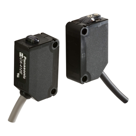
Basic Mark Sensor
LX-111 Series
INSTRUCTION MANUAL
850mW or less
(Power voltage 24V,Current consumption 35mA or less)
Power consumption
Mark mode: When mark detection ,ON.
0.2 mm² 4-core cabtyre
cable, 2m long
Division: Color code of cable
Brown : +V
Blue : 0V
Black : Output
Pink : Mode switching input
Division: Terminal No. of Connector
1 : +V
2 : Mode Switching input
3 : 0V
4 : Output
Net weight : Approx.110g
Packing weight: Approx.120g
Net weight : Approx.50g
Packing weight: Approx.55g
(Note 2)
Cable
Weight
Measurement conditions ,around Using temperature +23
Mark mode
Mark mode
Color Mode Color Mode
<PNP output type>
<PNP output type>
Mode switching input
(between output and 0V)
Short-circuit protection
Incorporated(Auto reset)
(between output and +V)
Operation indicator Orange LED(Light on when output is ON)
Color mode: Coincidence-ON
(Emitting wavelength : 640nm / 525nm / 470nm)
Enclosure: PBT
Operation panel, Lens: PC
Operation buttons: Silicone rubber
Work state lamp(LED lamp)
ON OFF
Mode switching input
Mode switching input
D5
D6
Mark Mode Low (OFF): 0 to 0.6V DC, or open
Color mode High (ON): 5V to +V DC
Mark Mode Low (ON): 0 to 2V DC
Color mode High (OFF): 5V to +V DC, or open
2
2
5
612 to 24V DC
Before performing the Teaching, be sure to confirm the setting of
mark mode or color mode.
In case of 2-point teaching of mark mode
Press “ON key” when facing
the measured color .Then the
LED will flicker slowly.
ON
OFF Light off
Press “OFF key” when facing
the background. Then the
LED will go out.
The threshold value is set at the mid-value between the step 1 and 2.
In case stable sensing is possible : Good.
In case stable sensing is impossible : ERR.
Note: When the system is in the state of ERR, please run Teaching again.
otherwise the system will use the last results of teaching.
RUN
GOOD
light on about 2s
The LED will flicker quickly.
About 5s later,go out.
RUN
ERR
Flicker slowly
ON
In case of 1-point teaching of color mode
After aligning the beam spot to the
mark to be detected. Press “ON
key” .
In case stable sensing is possible :Good.
In case stable sensing is impossible :ERR.
RUN
GOOD
light on about 2s
The LED will flicker quickly.
About 5s later,go out.
RUN
ERR
Note: When the system is in the state of ERR, please run Adjust Mode again.
otherwise the system will use the last results of adjusting.
Work state lamp
(LED lamp)
LED lamp have been fast
scintillation,will not be put out
Connector type / LX-111□-Z
24
(Ø22)
3
5 25
35
2-Ø4.5(Mounting hole)
47
57
5
2
Ø14.4
9.5
15
Cable type / LX-111□
(Ø22)
15
24
5 47
57
2
25
35
5
3
2-Ø4.5(Mounting hole)
71.5
© Panasonic Industrial Devices SUNX Suzhou Co., Ltd. 2014
PRINTED IN CHINA
About our sale network, please visit our website.
97, Huoju Road, Suzhou New District, Jiangsu, China
Phone: +86-512-6843-2580 FAX: +86-512-6843-2590
http://device.panasonic.cn/ac/c
2CAUTIONS
5I/O CIRCUIT DIAGRAMS
Mode switching input
12 to 24V DC ●
●
The models listed under “ SPECIFI-
CATIONS” come with CE Marking.
As for all other models, please contact our office.
Contact infomation for CE
<Until June 30 ,2013>
Panasonic Electric Works Europe AG
Rudolf-Diesel-Ring 2, D-83607 Holzkirchen, Germany
<From July 1 ,2013>
Panasonic Marketing Europe GmbH Panasonic Testing Center
Winsbergring 15, 22525 Hamburg,Germany
1
9
10 INTENDED PRODUCTS FOR CE MARKING
The Make Mode ‘Gain’ Function
Several conditions of the ‘Gain’ function
Conditions Values LED’s twinkle times
1 C = C - D*80% 1
2 C = C - D*60% 2
3 C = C - D*40% 3
4 C = C - D*20% 4
5 C = C 5
6 C = C + D*20% 6
7 C = C + D*40% 7
8 C = C + D*60% 8
9 C = C + D*80% 9
Conditions Values LED’s twinkle times
1 C = C - D*80% 1
2 C = C - D*60% 2
3 C = C - D*40% 3
4 C = C - D*20% 4
5(Note1) C = C 5
6 C = C + D*20% 6
7 C = C + D*40% 7
8 C = C + D*60% 8
9 C = C + D*80% 9
While sensing is unstable, the judgments to the reflected light variation
When the ‘Gain’ begins, the sensor is in the corresponding condition
with the LED’s twinkle times(X) after the LED is off for 0.5s
without any operations.
can be changed(Threshold value adjustment) through the
‘Gain’ function.
Note 2 : Value C stands for the threshold value;
Value D stands for the reflected light variation between
the mark(A) and the base(B).
Note 1 :Factory Setting Condition
(Which is the condition before
the adjustment of the
‘Gain’function.)
D
A
C
B
D
A
C
B
The Condition 5
D
A
B
D
A
C
The Condition 2
D
C
B
D
A
C
B
The Condition 8
Example:
A, B, C, D mean the value of the reflected light variation.
Note: Value A stands for the reflected light variation of the mark;
Value B stands for the reflected light variation of the base.
ON Zone
OFF Zone
The ‘Gain’ Function
ON Zone
OFF Zone
ON Zone
OFF Zone
LED twinkles for (5) times LED twinkles for (8) timesLED twinkles for (2) times
·For a better observation, please press the button OFF for one time at the
normal condition when the LED is off, and then press the button ON along
for approximately 6s until the LED is on. And now, the ‘Gain’ function
begins.
·After the ‘Gain’ function begins, you may adjust the conditions of the
‘Gain’ by the button ON/OFF.
·It is not necessary to teach again after the adjustment and the sensor
can be used immediately.
The adjustment of the‘Gain’
function and the display of the LED
‘Gain’ Function begins.
Judge the condition right now
with the twinkle times(X)
LED begins to
twinkle rapidly.
Adjust the condition with
the button ON/OFF
Returns to the normal condition
after 3s approximately.
ON (+)
OFF(-)
LED is off for 0.5s
Twinkle times of
LED
LED twinkles
rapidly for
approximately 3s
The operation of the ‘Gain’ function


