manuals.online logo
Brands
  1. Home
  2. •
  3. Brands
  4. •
  5. Panasonic
  6. •
  7. Accessories
  8. •
  9. Panasonic HG-S1010-AC User manual

Panasonic HG-S1010-AC User manual

INSTRUCTION MANUAL
Contact-Type Digital Displacement Sensor / Sensor Head Air-Driven Type
+*6Ƒ$&
MJE-HGSAC No.0074-51V
Thank you very much for purchasing Panasonic products. Read this Instruction Man-
ual carefully and thoroughly for the correct and optimum use of this product. Kindly
keep this manual in a convenient place for quick reference.
WARNING
ƔNever use this product as a device for personnel protection.
ƔWhen using devices for personnel protection, use products that meet the laws
and standards for personnel protection that apply in each region or country, such
as OSHA, ANSI and IEC.
This document provides a brief summary of mounting and other related information.
For detailed information, refer “our web site (https://panasonic.net/id/pidsx/global) ”
1STANDARDS AND REGULATIONS
ƔThis product conforms to the standards and regulations below.
<European Directives>
EMC Directive
2CONTENTS OF PACKAGE
Sensor head 1 pc.
Mounting nut 1 pc.
Sensor head fastening wrench 1 pc.
Air tube clamp 1 pc.
Instruction Manual (English / Japanese, Chinese / Korean) 1 pc. each
General Information for Safety, Compliance, and Instructions(23 languages) 1 pc.
3DESCRIPTION OF PARTS
When air is supplied
Spindle
Seal cap (Note)
Operation indicator
(Orange / Green)
Mounting nut
Air tube joint
Probe
Sensor head connection
cable connector
Note: The seal cap is provided as a maintenance part. HG-SASCX5 (5 pcs. per set)
4MOUNTING
Mounting on the housing
Ɣ1RWHWKDWWKHPRXQWLQJGLUHFWLRQRIWKHSURYLGHGPRXQWLQJQXWGLႇHUVDFFRUGLQJ
to the thickness of the housing.
1. Open a hole in the housing in which the
sensor head will be mounted
Thickness of
the housing Mounting hole
ȭ8H7 +0.015
0mm
2.
Insert the sensor head into the hole you opened in the
housing, and fasten lightly with the provided mounting nut.
Thickness of the housing
AB
HG-S1010-AC, HG-S1110-AC 6.5 to 10mm 10 to 12.5mm
A
Housing
B
Housing
Thread
Thread
Mounting nut with the
thread facing down
Mounting nut with the
thread facing up
Note: Please use within a the thickness of the housing range of 6.5~12.5mm.
Mounting nut
(Accessory)
3. Fasten the sensor head.
Tighten the mounting nut with a wrench
while holding the sensor head in place
with the sensor head fastening wrench as
shown.Tighten to a torque of 12.5N·m or
less.
Mounting nut
(Accessory)
Sensor head
fastening wrench
(Accessory)
Connecting the sensor head connection cable
Ɣ :KHQDWWDFKLQJWKHFRQQHFWRUPDNHVXUHLWLV¿UPO\WLJKWHQHG,IORRVHWKHFRQ-
QHFWRUPD\FRPHRႇDQGFDXVHDQHUURU
ƔWhen disconnecting, always make sure that the fastening ring has been com-
pletely loosened before pulling out the cable.Risk of damage if you pull the cable
with excessive force (15N or more) with the fastening ring tightened.
ƔSensor head connection cables with an L-shaped connector cannot be used.
How to connect
1. Insert the sensor head connection
cable into the connector for the
sensor head connection cable on
the sensor head.
2. Turn the fastening ring on the sen-
sor head cable in the direction
VKRZQWR¿UPO\WLJKWHQWKHULQJ
1. Insert
2. Tighten
fastening ring
How to remove
1. Turn the fastening ring on the sen-
sor head cable in the direction
shown to loosen the ring.
2. Grasp each connector on the sen-
sor head connection cable and pull
out to remove.
2. Pull out
1.
Loosen
Connecting the air tube
Ɣ :KHQFRQQHFWLQJWKHDLUWXEH¿UPO\VHFXUHLWZLWKWKHDLUWXEHFODPSSURYLGHG,I
the air tube is used without inserting or securing it properly, there is a danger that
WKHDLUWXEHPD\FRPHRႇZKLOHLWLVEHLQJXVHG
How to connect
1. While loosening the air tube clamp, slide it from the tip of the air tube and then
release it when it reaches halfway through the tube.
2. Insert the tip of the air tube until it reaches the root of the joint on the sensor
head.
3. Move the air tube clamp and secure the tip of the air tube.
4-mm-diameter air tube
Air tube clamp
(Accessory)
How to disconnect
1. While loosening the air tube clamp, move it halfway
through the air tube.
2. Grasp the sensor head and pull out the air tube.
Note: Take care not to lose the air tube clamp.
5AIR CIRCUIT (RECOMMENDED)
Ɣ &UHDWHDQDLUFLUFXLWOLNHWKHRQHUHFRPPHQGHGVKRZQLQWKH¿JXUHEHORZDQG
if necessary, adjust the speed of the spindle with the speed control valve.
Air pressure source
Precision regulator
3-port solenoid valve Speed control valve
Filter + Mist separator + Regulator
Notes: 1) Supply clean air (free from moisture, oil, dust, or other foreign objects) to this product.
2) Air pressure may decrease, depending on the length of the air pipe from the air supply source or any pneu-
PDWLFFRPSRQHQWVVXFKDVQHHGOHYDOYHVVSHHGFRQWUROOHUVRUPLQL¿OWHUVWKDWDUHDGGHG7DNHFDUHWRHQ-
VXUHWKDWDLUSUHVVXUHVXSSO\WRWKHSURGXFWLVVXႈFLHQW6HOHFWSQHXPDWLFFRPSRQHQWVVXLWDEOHIRUWKHVXS-
plied air pressure.
3) The 3-port solenoid valve and speed control valve have their respective mounting directions. Mount each
valve in their correct direction by referring to the above diagram.
4)
$¿OWHUZLWKD UDWHG¿OWUDWLRQ RIȣP RUOHVV DQGD PLVWVHSDUDWRU ZLWKD UDWHG¿OWUDWLRQ RIȣm or less are
recommended.
6SPECIFICATIONS
Type General purpose High precision
Model No.
(Note 2)
HG-S1010-AC HG-S1110-AC
With no seal cap
mounted
With no seal cap
mounted
Position detection method Optical absolute linear encoder method
Measurement range 10mm (Note 3)
Stroke 10.5mm or more (Note 3)
Measuring
force
(Note 4)
Downward mount (Note 5) (Note 5) (Note 5) (Note 5)
Upward mount (Note 5) (Note 5) (Note 5) (Note 5)
Side mount (Note 5) (Note 5) (Note 5) (Note 5)
Resolution 0.5μm0.1μm
Sampling cycle 1ms
Indication
accuracy
(P-P)
Full range ȝPRUOHVV ȝPRUOHVV
Limited range ȝPRUOHVVDQ\ȝP ȝPRUOHVVDQ\ȝP
Operation indicator Equipped (2-color LED: Orange, green)
Working pressure range 0.14 to 0.16MPa 0.035 to
0.045MPa 0.14 to 0.16MPa 0.035 to
0.045MPa
Capacity to resist pressure 0.2MPa
8VDEOHÀXLG Dry air (Dew point temperature: -10°C or lower)
Applicable tube Outside diameter: 4mm / Inside diameter: 2.5mm
Protective structure (Note 6) IP67(IEC) ņIP67(IEC) ņ
Contamination level 2
Elevation 2,000m or lower (Note 8)
Mechanical life (Note 7) 30 million times or more (typical value)
Tip deviation amount ȝPW\SLFDOYDOXH
Grounding method Capacitor grounding
Insulation resistance 0ȍRUPRUHDW9'&
Hot swap function Incorporated
Ambient temperature -10 to +55°C (No dew condensation or icing allowed), Storage: -20 to +60°C
Ambient humidity 35 to 85% RH, Storage: 35 to 85% RH
Material Body: Zinc, Holder: Stainless steel, Spindle: Tool steel, Probe: Ceramic (Note 9)
Weight (main unit only) Approx. 80g
1RWHV0HDVXUHGDWDQDPELHQWWHPSHUDWXUHRI&XQOHVVRWKHUZLVHVSHFL¿HG
2) Connect an
HG-S series controller (manufactured in or after February 2019).
3) The position that represents "0" as an absolute value is a position where the spindle is pushed further down
from the bottom dead point by 0.1mm or more. The term "stroke" indicates the total stroke length from the
bottom dead point to the top dead point.
4) Measuring force changes with the air pressure used. Removing the seal cap enables the product to be used
as the low measuring force type. For details on how to remove the seal cap, refer to " 8MAINTENANCE".
5) For the relationship between supplied air pressure and measuring force or between measuring force and
SXVKHGVSLQGOHSRVLWLRQVHHWKH¿JXUHVEHORZ)RUXSZDUGPRXQWZLWKRXWDVHDOFDSVXEWUDFW1IURPWKH
PHDVXULQJIRUFH)RUVLGHPRXQWVXEWUDFW1IURPWKHPHDVXULQJIRUFH7KHIROORZLQJ¿JXUHVDUHRQO\W\SL-
FDOH[DPSOHVDQGWKHVHUHODWLRQVKLSVGLႇHUGHSHQGLQJRQWKHDVVHPEO\DFFXUDF\RIWKHSURGXFWRUWKHDEUD-
sion status of sealing materials.
ƔWhen no seal cap is mounted
Pushed spindle position [mm]
Measuring force [N]
<Downward mount (typical example)>
<Side mount (typical example)>
Pushed spindle position [mm]
Measuring force [N]
<Upward mount (typical example)>
Pushed spindle position [mm]
Measuring force [N]
<Downward mount (typical example)>
Measuring force [N]
Pushed spindle position [mm]
6) Protective structure is not applicable when the sealing portions have deteriorated or become damaged. The
protection level is zero when the seal cap is removed.
7) Typical value in a clean environment with no contact with dust or liquids such as water and oil.
The sealing material (O-ring) for the seal cap must be replaced at appropriate intervals. For approximate re-
placement intervals, refer to "How to replace the seal cap" in " 8MAINTENANCE".
8) Do not use or store this product in environments where ambient air is pressurized to an air pressure higher
than the atmospheric pressure at an altitude of 0 m.
9) The probe is also available as an option.
7CAUTIONS
The special sensor head HG-SƑLVGHVLJQHGWREHXVHGZLWKWKHFRQWUROOHU
HG-SCƑ,IXVHGZLWKRWKHUWKDQWKHVSHFLDOVHQVRUFRQWUROOHURSWLRQWKHVSHFL¿FD-
tions will not be met and product malfunctioning or damage may occur.
ƔThis device has been developed / produced for industrial use only.
Ɣ'RQRWXVHWKLVSURGXFWRXWVLGHWKHUDQJHRIWKHVSHFL¿FDWLRQV5LVNRIDQDFFLGHQW
and product damage. There is also a risk of a noticeable reduction of service life.
ƔDeviations may occur in the measured value at the bottom dead point. Do not use
the bottom dead point as a reference. The position where the spindle is pushed
further down from the bottom dead point by 0.1mm or more must be used as the
reference point.
ƔDo not wire in parallel with a high-voltage line or power line, or run through the
same conduit. Risk malfunctioning due to induction.
ƔDo not use the product during the initial transient time after the special controller
HG-SCƑLVWXUQHG21
ƔDo not apply stress such as excessive bending or pulling to the extracted part of a
cable.
ƔWhen attaching the sensor head connection cable to this product, do not apply
force to the product.
ƔOnly one joint (optional) can be installed to one sensor head.
ƔThis product is suitable for indoor use only.
ƔAvoid dust, dirt, and steam.
ƔDo not use this sensor in places where it may come in contact with corrosive gas-
es, ozone, or other harmful gases.
ƔEnsure that the product does not come into contact with organic solvents such as
thinner.
ƔEnsure that the product does not come into contact with strong acid or alkaline.
ƔEnsure that the product does not come into contact with oil or grease.
Ɣ
7KLVSURGXFWFDQQRWEHXVHGLQDQHQYLURQPHQWFRQWDLQLQJÀDPPDEOHRUH[SORVLYHJDVHV
Ɣ3HUIRUPDQFHPD\QRWEHVDWLVIDFWRU\LQDVWURQJHOHFWURPDJQHWLF¿HOG
ƔThis product is a precision device. Do not drop or otherwise subject to shock. Risk
of product damage.
ƔMount the sensor unit perpendicular to the measured surface. Mounting the sen-
VRUXQLWREOLTXHO\ PD\QRWRQO\UHVXOWLQPHDVXUHPHQWHUURUEXW DOVRVLJQL¿FDQWO\
shorten its service life.
ƔDo not allow excessive horizontal force to be applied to the spindle.This may
cause reduced accuracy and durability.
ƔMount a pressure-reducing valve to use the product within the allowable working
pressure range. Excessive pressure may result in failure or damage.
ƔDo not use air containing foreign objects (such as carbon powder or dust), water,
or oil. Doing so may result in electric shock or failure. To prevent such problems,
WDNHDSSURSULDWHPHDVXUHVVXFKDVPRXQWLQJDLU¿OWHUVRUPLVWVHSDUDWRUV
Ɣ %HIRUHSHUIRUPLQJPDLQWHQDQFHLQVSHFWLRQRUFOHDQLQJDOZD\VVKXWRႇDLUVXSSO\
completely and check that the pressure inside the product and piping is zero. Fail-
ure to do so may result in accidents or failures due to air pressure.
ƔWhen the product becomes unusable or unneeded, dispose of the product appro-
priately as industrial waste.
ƔNever attempt to disassemble, repair, or modify the product.
8MAINTENANCE
How to replace the probe
ƔAlways secure the spindle to prevent rotation before replacing the probe. Risk of
product damage if an excessive torque (0.2N·m or more) is applied to the spindle.
ƔIf the seal cap is scratched or damaged during probe replacement, the
VSHFL¿FDWLRQVRIWKHSURWHFWLYHVWUXFWXUHPD\QRWEHVDWLV¿HG
1.
Turn the probe screw in the direction of the arrow and remove the probe from the
spindle. When turning the probe screw, hold the cut face of the spindle with the
provided sensor head fastening wrench to prevent the spindle from turning.
Hold the sensor head fastening wrench in place, and turn only the probe.
Sensor head
fastening wrench
(Accessory)
Probe
Turn
2. Attach the new probe to the spindle. The tightening
torque should be 0.4N·m or less. Make sure that the
probe does not come OFF.
When turning the probe screw, hold the cut face of the
spindle with the provided sensor head fastening wrench
to prevent the spindle from turning.
Hold the sensor head fastening wrench in place, and
turn only the probe. Turn
How to replace the seal cap
Replace the seal cap at appropriate intervals according to the deterioration status of
the sealing material.
Replace the seal cap when the number of sliding operations reaches approximately
¿YHPLOOLRQ
ƔWhen removing or mounting the seal cap, always remove the product from the
housing.
ƔWhen removing or mounting the seal cap, stop supplying air.
ƔTo prevent problems, replace the seal cap before the internal O-ring becomes
worn.
How to remove
1. Remove the probe.
2. While pulling the seal cap, expose the
edge of the O-ring.
3. Loosen the seal cap by rotating it in the
direction indicated by the arrow.
4. After loosening the seal cap completely,
pull it out.
5. Finally, remove the O-ring.
Seal cap
O-ring
How to mount
1. Mount the O-ring in the specified posi-
tion.
2. Slide the seal cap onto the spindle and
move it to a position where it can rotate
at no load.
3. Push in the seal cap while rotating it in
the direction indicated by the arrow.
Note: Check that the O-ring does not protrude.
Seal cap
O-ring
Panasonic Industrial Devices SUNX Co., Ltd.
https://panasonic.net/id/pidsx/global
Please visit our website for inquiries and about our sales network.
PRINTED IN JAPAN © Panasonic Industrial Devices SUNX Co., Ltd. 2020

This manual suits for next models

2

Other Panasonic Accessories manuals

Panasonic MA27P01 User manual

Panasonic

Panasonic MA27P01 User manual

Panasonic MA4Z159 User manual

Panasonic

Panasonic MA4Z159 User manual

Panasonic MA4X714 (MA714) User manual

Panasonic

Panasonic MA4X714 (MA714) User manual

Panasonic KX-HNS102FX User manual

Panasonic

Panasonic KX-HNS102FX User manual

Panasonic PD50 User manual

Panasonic

Panasonic PD50 User manual

Panasonic KX-HNS103EX User manual

Panasonic

Panasonic KX-HNS103EX User manual

Panasonic VF Series User manual

Panasonic

Panasonic VF Series User manual

Panasonic HG-C1030 User manual

Panasonic

Panasonic HG-C1030 User manual

Panasonic FM-200 Series User manual

Panasonic

Panasonic FM-200 Series User manual

Panasonic MA3J1470G User manual

Panasonic

Panasonic MA3J1470G User manual

Panasonic SR-CN108 User manual

Panasonic

Panasonic SR-CN108 User manual

Panasonic LS-400 Series User manual

Panasonic

Panasonic LS-400 Series User manual

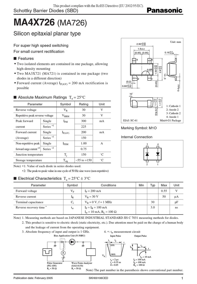
Panasonic MA4X726 (MA726) User manual

Panasonic

Panasonic MA4X726 (MA726) User manual

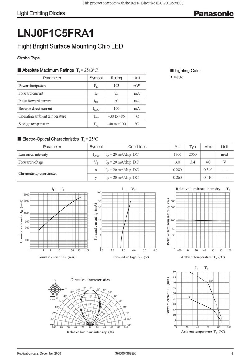
Panasonic Light Emitting Diodes LNJ0F1C5FRA1 User manual

Panasonic

Panasonic Light Emitting Diodes LNJ0F1C5FRA1 User manual

Panasonic PE Series User manual

Panasonic

Panasonic PE Series User manual

Panasonic HL-C1-WL Series User manual

Panasonic

Panasonic HL-C1-WL Series User manual

Panasonic MA Motion Sensor Series User manual

Panasonic

Panasonic MA Motion Sensor Series User manual

Panasonic DP-M Series User manual

Panasonic

Panasonic DP-M Series User manual

Panasonic MA3X157A User manual

Panasonic

Panasonic MA3X157A User manual

Panasonic Schottky Barrier Diodes MA3SE020G User manual

Panasonic

Panasonic Schottky Barrier Diodes MA3SE020G User manual

Panasonic MA24F70 User manual

Panasonic

Panasonic MA24F70 User manual

Panasonic MA3D752 User manual

Panasonic

Panasonic MA3D752 User manual

Panasonic PX-2 Series User manual

Panasonic

Panasonic PX-2 Series User manual

Panasonic HL-C2 Series User manual

Panasonic

Panasonic HL-C2 Series User manual

Popular Accessories manuals by other brands

BEMKO SES60WH instructions

BEMKO

BEMKO SES60WH instructions

Philips P-5794-B Specifications

Philips

Philips P-5794-B Specifications

ZIGBEE Z312 user manual

ZIGBEE

ZIGBEE Z312 user manual

Zehnder Rittling 0-10V67 on wall Installer manual

Zehnder Rittling

Zehnder Rittling 0-10V67 on wall Installer manual

Humboldt SmartRock HG-4040 manual

Humboldt

Humboldt SmartRock HG-4040 manual

Stack STACK101 installation instructions

Stack

Stack STACK101 installation instructions

KARPO Fly Fantom Extralight 3 manual

KARPO Fly

KARPO Fly Fantom Extralight 3 manual

CARLO GAVAZZI PD30CTB BP Series instruction manual

CARLO GAVAZZI

CARLO GAVAZZI PD30CTB BP Series instruction manual

Star ECONO SEC-CCY Operation manual

Star

Star ECONO SEC-CCY Operation manual

Oceanic Systems 3281 Installation and operating instructions

Oceanic Systems

Oceanic Systems 3281 Installation and operating instructions

SkylinkHome Deluxe Home Monitoring Kit user manual

SkylinkHome

SkylinkHome Deluxe Home Monitoring Kit user manual

Philips Sonicare 7000 manual

Philips

Philips Sonicare 7000 manual

Cedes TOF/Spot Quick guide manual

Cedes

Cedes TOF/Spot Quick guide manual

Balluff BTL7-S5 B-M Series Condensed guide

Balluff

Balluff BTL7-S5 B-M Series Condensed guide

Unico 10000 MAH quick start guide

Unico

Unico 10000 MAH quick start guide

Byron SX-80 Installation and operation instruction

Byron

Byron SX-80 Installation and operation instruction

x-sense C2 user manual

x-sense

x-sense C2 user manual

Honeywell DC515SP2 Getting started

Honeywell

Honeywell DC515SP2 Getting started

manuals.online logo
manuals.online logoBrands
  • About & Mission
  • Contact us
  • Privacy Policy
  • Terms and Conditions

Copyright 2025 Manuals.Online. All Rights Reserved.