manuals.online logo
Brands
  1. Home
  2. •
  3. Brands
  4. •
  5. Panasonic
  6. •
  7. Accessories
  8. •
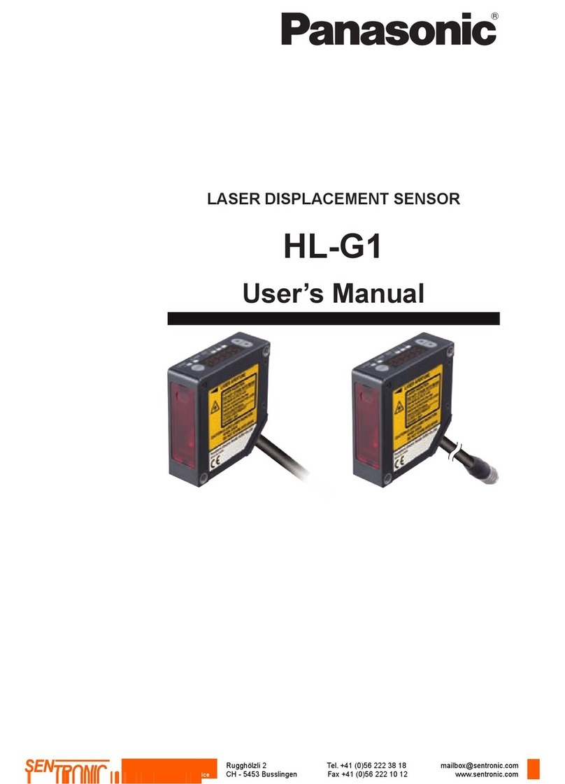
  9. Panasonic HL-C21C Series User manual

Panasonic HL-C21C Series User manual

INSTRUCTION MANUAL
Ultra High-Speed,High-Accuracy Laser Displacement Sensor
RS-232C type Ethernet type
 
CMJE-HLC2C(04) No.0040-98V
Thank you for purchasing our product. Be sure to read this manual before use in
order to ensure the safe and proper operation of this product. Keep this manual at
hand for your reference after reading it through.
For details, be sure to refer to the HL-C2 Series User’s Manual in PDF, and use the
HL-C2AiM software or the compact programmable display (sold separately) to make settings
for use. The Instruction Manual in PDF is in the setup CD-ROM provided with the product.
WARNING
This product is intended to detect the objects and does not have the control func-
tion to ensure safety such as accident prevention.
Do not use the product as a sensing device to protect human body.
Please use the products that comply with local laws and standards for human

Install a fail-safe device when the product is used for the purpose that has a pos-
sibility of physical injury or serious extended damage.


GETTING STARTED
 Check the following items before using this product.
Controller Type
Check the model number on the side of the controller.
The model number is provided with the name of the product.
Bundled Items
Make sure that the following items are in the package.
 Controller × 1
 USB cable (2m) × 1
 Instruction Manual (This publication) × 1
 HL-C2 Series Setup CD-ROM × 1
 

Note: HL-C2C
1OVERVIEW
 This product is a dedicated controller for the HL-C2 Series Ultra High-Speed,


Up to two dedicated sensor heads can be connected freely to the product, and each
sensor head makes it possible to make computation or independent measurement.
  
measurement and output settings. Furthermore, measured values as well as the

2PRECAUTIONS
This product was developed and manufactured for use in industrial environments.


Do not disassemble or remodel the product. Electrical shock or smoke generation
may occur.
Connect the electric wire securely with the terminal screws. Imperfect connection
may cause abnormal heat or smoke generation.

Do not touch the terminal during energization of the product, to prevent electrical shock.
Mounting
Controller
 Install the controller with sufficient space secured around the controller. The
improper installation of the controller may result in malfunctioning caused by an
excessive temperature rise.
 If the controller is mounted internally on the place where air circulation is blocked
such as in a control board, the ambient temperature will rise due to heat gener-
ated by the controller. In such case, forced cooling is required.
 Vent holes for heat radiation are provided at the top and bottom of controller unit.
Provide adequate space for heat radiation, not to block the holes.
Wire Connections and Connectors
 Connect all wirings securely according to the explanations for I/O circuit and de-
scription on the unit.
 Turn off the power of controller before connecting or disconnecting the connec-
tors. When connecting or disconnecting the connectors, be sure to hold the con-
nector area not to apply extra force to the cable.
 Be careful not to touch terminals or to let foreign objects get in the connector after
disconnecting connectors.
Warming Up

performance of the product.
Operating Temperature
Ambient temperature and humidity
 -

 
however, use the controller in places where a drastic temperature change may
result in dew condensation.
Environment

  
   

Do not install the product in the following conditions.
 Where the ambient temperature, ambient humidity or ambient illuminance of

 Where dew condensation occurs due
to rapid temperature change
  
powder and salt
 Where direct sunlight is received
 In an atmosphere of corrosive gas or

 Where load is applied to the product
 Where water, oil or chemicals splashes
 Where heavy vibration or impact is applied

In an atmosphere which is likely to be exposed to organic solvent such as benzene,
thinner or alcohol, or to strong alkaline materials such as ammonia or sodium hydroxide
Noise Immunity
 Install the product as far away as possible from noise source such as high-voltage
lines, high-voltage device, power lines, power device, machines which generate a
large starting and stopping surge, welding machines and inverter motor.
 Install the product as far away as possible from wireless device that has a trans-
mitter such as amateur radio device.
 For input signal lines and output signal lines, run them separately, not rolled up
  
signal lines should be connected as short as possible.
 

 Use an exclusive class D frame ground and avoid sharing the ground with other
devices. This may produce an opposite effect.
Power Supply
Power Supply


 When using a commercial switching regulator, be sure to ground the frame ground


When using a transformer in the power supply, be sure to use an insulated transform-
er. The product or the power supply may be damaged if an auto transformer is used.

Use an insulated power supply that incorporates a protective circuit to protect against ab-
normal voltages from the power line. When using a power supply that does not incorporate
a protective circuit, be sure to supply power through a protective element such as a fuse.
Precautions for positive ground environment
 When the sensor is used in a positive ground environment, a short circuit may oc-
cur via the ground of the personal computer or USB.
 Please prepare a separate power supply for the sensor, and do not connect the
positive (+) terminal.
 When performing a positive ground of the DC power supply of the equipment, do

Power Supply Sequence for Controller


 If the I/O power turns off prior to the controller, the controller detects the change in
level of input signals and this may cause wrong operation.
 Leave an interval for at least 10 seconds between turning off the controller and
turning on the power again.
 -
pleted), depending on the settings saved. No outputs are determined during
startup. Do not output anything during the period.
 Do not turn off the power while saving the settings. In the worst case, the system
of controller is destroyed and may fail to restart.
Instantaneous Power Failure

If an instantaneous power failure occurs, the system operates continuously, or goes
to the same state as power-on state, depending on the duration of power failure. Do
not use the system in the environment where an instantaneous power failure occurs.
3NOMENCLATURE OF TERMINAL BLOCK
1 2 3 54
17*2
6
7
8
9
10
11*1
15
14
16
13
12
NPN PNP Function
Terminal

(V)1 
 
(I)1 
(V)2 
 
(I)2 


LSRB
Laser control input (for Head B) Laser stop during short circuit
(
-
) Common (-)
IL IL
-
Remote interlock Laser stop when opened
(
-
) IL+ Remote interlock common
External I/O terminal
ZS2
Zero set input (for OUT2) ON during short circuit*
TM2
Timing input (for OUT2) ON during short circuit
RS2
Reset input (for OUT2) ON during short circuit
(
-
) Common (-)
 
ST2 Strobe output (for OUT2)
HI2 Judgment HI output (for OUT2)
 
LO2 Judgment LO output (for OUT2)
ΖReserved terminal
(
-
) (+) Common (-) / Common (+)
M0
Memory change (16 ways)
M1
M2

(
-
) Common (-)
External I/O and power terminals
ZS1
Zero set input (for OUT1) ON during short circuit*
TM1
Timing input (for OUT1) ON during short circuit
RS1
Reset input (for OUT1) ON during short circuit
ΖReserved terminal
ΖReserved terminal
(
-
) Common (-)
 
ST1 Strobe output (for OUT1)
HI1 Judgment HI output (for OUT1)
 
LO1 Judgment LO output (for OUT1)
ΖReserved terminal
(
-
) (+) Common (-) / Common (+)
24V 24V DC input for power supply
0V Power supply ground 0V
 Frame ground
* Turn off the terminal in case short circuit lasts for more than
one second.
1. POWER Indicator
2. 
3. 
4. 
5. 
6. 
7. Laser Control Terminal
8. Remote Interlock Terminal
9. USB Connector
10. Programmable Display Connection Connector
11.
 is equipped.)
12. I/O Terminal
13. Power Terminal
14. 
15. Sensor Head B Connection Connector
16. DIN Rail Mounting Hook
17.
Ethernet Connector (*2 Only  is equipped.)
4SPECIFICATIONS
Model No.  HL-C2C HL-C2CE HL-C2C-P HL-C2CE-P
Ethernet HL-C21C HL-C21CE HL-C21C-P HL-C21CE-P
Supply voltage 
Current consumption


Sampling cycle 

Voltage (Note 2)

Output range during normal status: -10.0 to +10.0V, Output at abnormal status: -10.8V or +10.8V









Strobe output
NPN transistor open collector
 
 

 Residual voltage: 1V or less

 
PNP transistor open collector
 
 

 Residual voltage: 1V or less

 
Output operation

Judgment output: Open when the output is ON(output operates).
Strobe output: Open when the output is ON(data is determined).
Short circuit protection 
Remote interlock input
Laser emission is delayed when connected to Common (-).
Laser emission stop at open
Laser emission is delayed when connected to IL (+).
Laser emission stop at open
Various types of input
Laser control input
Laser emission is stopped when connected to Common (-).
Laser is emitted immediately after opened.
Laser emission is stopped when connected to external power (+).
Laser is emitted immediately after opened.
Zero set input
Zero set is ON when connected with Common (-).
Zero set turns to OFF after continuously
connected to Common (-) for one second.
Zero set is ON when connected with external power (+).
Zero set turns to OFF after continuously con-
nected to external power (+) for one second.
Timing input ON at / during connection to Common (-)
(depending on analysis mode)
ON at / during connection to external power (+)
(depending on analysis mode)
Reset input
Reset is done when connected to Common (-).
Reset is done when connected to external power (+).
Memory change input


 



 
USB interface USB 2.0 Full-speed (USB 1.1 compatible) compliant
Connecting sensor head Maximum 2 sensor heads with connection compatibility
Setting / data display Compact programmable display (sold separately)
Indicator
Power indicator
(POWER) 
Laser radiation 
 
Enclosure rating 
Pollution degree 2
Insulation resistance 
Dielectric strength
Commercial frequency 
Impulse 
Vibration resistance 

Shock resistance Withstanding 196m/s2
 
 
 2,000m or less
Material Case: Polycarbonate
Weight 
 
Ethernet type: Conformed to EMC Directive
      -

and measurement object: white ceramic.
The HL-C2CE(-P) and HL-C21CE(-P
Foreign Trade Law.
2) The linearity is F.S.=20V to digital measurement value. Response delay time is the period after update of
measurement value.
      
measurement value.
4) Only  is equipped.
  is equipped.
5APPLICABLE STANDARDS / REGULATIONS
Make sure that the length of signal and power lines connected to the

  

each as shown below.
 
)

or less 
or less
Rotate the ferrite core one
or more times before use.
When the extension cable is used.

or less
 Contact for CE


6I/O CIRCUIT
NPN type










+24V

NPN open collector output
Main circuit
No-voltage input
Strobe output
ST1/2
Judgment output
HI 1/2
Judgment output
LO 1/2
Judgment output

Common (
-
)
Zero set input ZS 1/2
Timing input TM 1/2
Reset input RS 1/2
Memory change input

Laser control input

Common (
-
)
0V

Load
Load
Load
Load
Load
Extemal power

Main unit power

including ripple of

*1
Controller in-
ternal circuit
External connec-
tion example
IN
Common (-)
No-voltage input
IN
Common (-)
NPN transistor open
collector output
or
*1
 Refer to the HL-C2
PNP type
*1
Voltage input PNP transistor open
collector output
or
IN
Common (-)
IN
Common (-)


Strobe output
ST1/2
Judgment output
HI 1/2
Judgment output
LO 1/2
Judgment output

Timing input TM 1/2
Reset input RS 1/2
Memory change input

Laser control input

Extemal power

Controller in-
ternal circuit
External connec-
tion example





+24V
Common (+)
Common (
-
)
Zero set input
ZS 1/2
Common (
-
)
0V

Load
Load
Load
Load
Load
Main unit power

including ripple of

*1
PNP open collector output
Main circuit
Voltage input
 Refer to the HL-C2
http://panasonic.net/id/pidsx/global




 

This manual suits for next models

7

Other Panasonic Accessories manuals

Panasonic MA3X717E User manual

Panasonic

Panasonic MA3X717E User manual

Panasonic SC-GU1-485 User manual

Panasonic

Panasonic SC-GU1-485 User manual

Panasonic MAZDxxx Series User manual

Panasonic

Panasonic MAZDxxx Series User manual

Panasonic HL-C1-WL Series User manual

Panasonic

Panasonic HL-C1-WL Series User manual

Panasonic MA6Z121 User manual

Panasonic

Panasonic MA6Z121 User manual

Panasonic NN-SE9**S User manual

Panasonic

Panasonic NN-SE9**S User manual

Panasonic SL-CH22 User manual

Panasonic

Panasonic SL-CH22 User manual

Panasonic MALS180XG User manual

Panasonic

Panasonic MALS180XG User manual

Panasonic KX-HNS102FX User manual

Panasonic

Panasonic KX-HNS102FX User manual

Panasonic CF-VNP011AU User manual

Panasonic

Panasonic CF-VNP011AU User manual

Panasonic MA27D30 User manual

Panasonic

Panasonic MA27D30 User manual

Panasonic KX-HNS103 User manual

Panasonic

Panasonic KX-HNS103 User manual

Panasonic MA3J142A User manual

Panasonic

Panasonic MA3J142A User manual

Panasonic MA3D750 User manual

Panasonic

Panasonic MA3D750 User manual

Panasonic HL-G1*A-RA-C5 Series User manual

Panasonic

Panasonic HL-G1*A-RA-C5 Series User manual

Panasonic Multi Chip Discrete UP05C8B User manual

Panasonic

Panasonic Multi Chip Discrete UP05C8B User manual

Panasonic HL-C211F User manual

Panasonic

Panasonic HL-C211F User manual

Panasonic Light Emitting Diodes LNJ214R8ARA User manual

Panasonic

Panasonic Light Emitting Diodes LNJ214R8ARA User manual

Panasonic EQ-500 Series User manual

Panasonic

Panasonic EQ-500 Series User manual

Panasonic MA3S7810G User manual

Panasonic

Panasonic MA3S7810G User manual

Panasonic MA3Z793 (MA793) User manual

Panasonic

Panasonic MA3Z793 (MA793) User manual

Panasonic MA22D17 User manual

Panasonic

Panasonic MA22D17 User manual

Panasonic MA6X124 (MA124) User manual

Panasonic

Panasonic MA6X124 (MA124) User manual

Panasonic MA271110G User manual

Panasonic

Panasonic MA271110G User manual

Popular Accessories manuals by other brands

BAPI VOC Installation and operating instructions

BAPI

BAPI VOC Installation and operating instructions

Hally-Gally Piccolo 20.02.118 Assembly instructions

Hally-Gally

Hally-Gally Piccolo 20.02.118 Assembly instructions

Burg Wächter DG8500 Assembly and user's manual

Burg Wächter

Burg Wächter DG8500 Assembly and user's manual

Basalte Sentido KNX Series installation manual

Basalte

Basalte Sentido KNX Series installation manual

S+S Regeltechnik Premasreg 7165 Operating Instructions, Mounting & Installation

S+S Regeltechnik

S+S Regeltechnik Premasreg 7165 Operating Instructions, Mounting & Installation

Orbis PROXIMAT PRO CR quick start guide

Orbis

Orbis PROXIMAT PRO CR quick start guide

VOLTCRAFT SL-10C operating instructions

VOLTCRAFT

VOLTCRAFT SL-10C operating instructions

Focusrite Red 4Pre user guide

Focusrite

Focusrite Red 4Pre user guide

SICK WSE4F operating instructions

SICK

SICK WSE4F operating instructions

Di-soric UGUTI 6/70 G6-RB5 manual

Di-soric

Di-soric UGUTI 6/70 G6-RB5 manual

ROSE DISPLAYS ECONOFRAME WITH WINDOW MOUNTS instruction sheet

ROSE DISPLAYS

ROSE DISPLAYS ECONOFRAME WITH WINDOW MOUNTS instruction sheet

American Standard FloWise Showerhead 1660.715 installation instructions

American Standard

American Standard FloWise Showerhead 1660.715 installation instructions

Lencore i.Net G3475 user guide

Lencore

Lencore i.Net G3475 user guide

Vox JamVOX Installation & setup guide

Vox

Vox JamVOX Installation & setup guide

Aegisound 05-001003 user manual

Aegisound

Aegisound 05-001003 user manual

ETC Echoflex Elaho installation guide

ETC

ETC Echoflex Elaho installation guide

NorthStar BR24 - MOUNTING TEMPLATE A4 1-1 Mounting template

NorthStar

NorthStar BR24 - MOUNTING TEMPLATE A4 1-1 Mounting template

Action Sports Stats instruction manual

Action Sports

Action Sports Stats instruction manual

manuals.online logo
manuals.online logoBrands
  • About & Mission
  • Contact us
  • Privacy Policy
  • Terms and Conditions

Copyright 2025 Manuals.Online. All Rights Reserved.