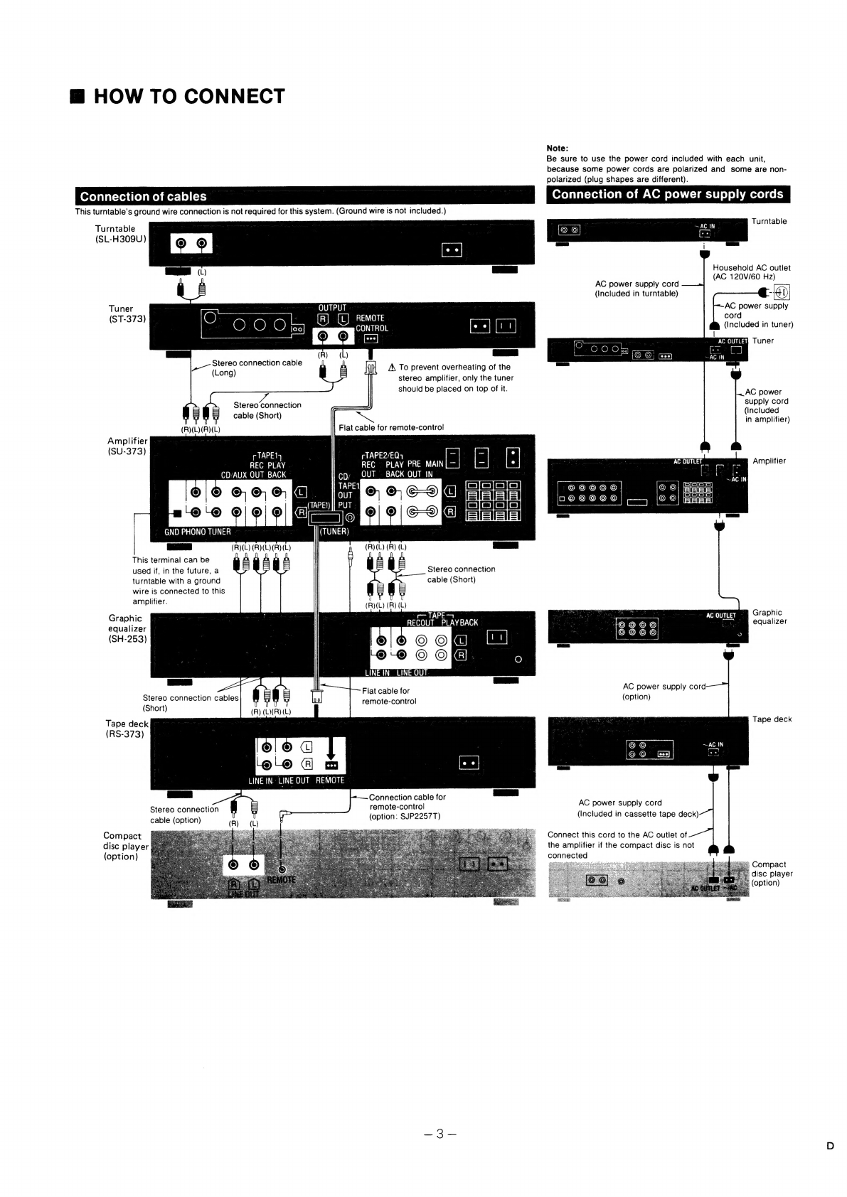
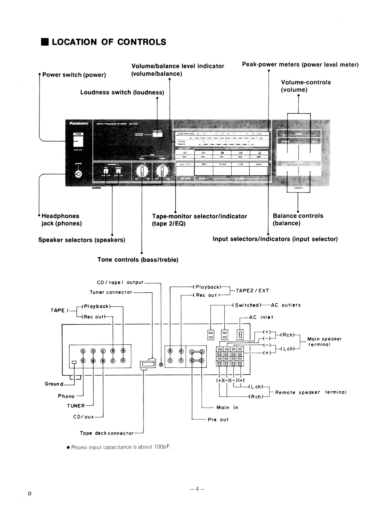
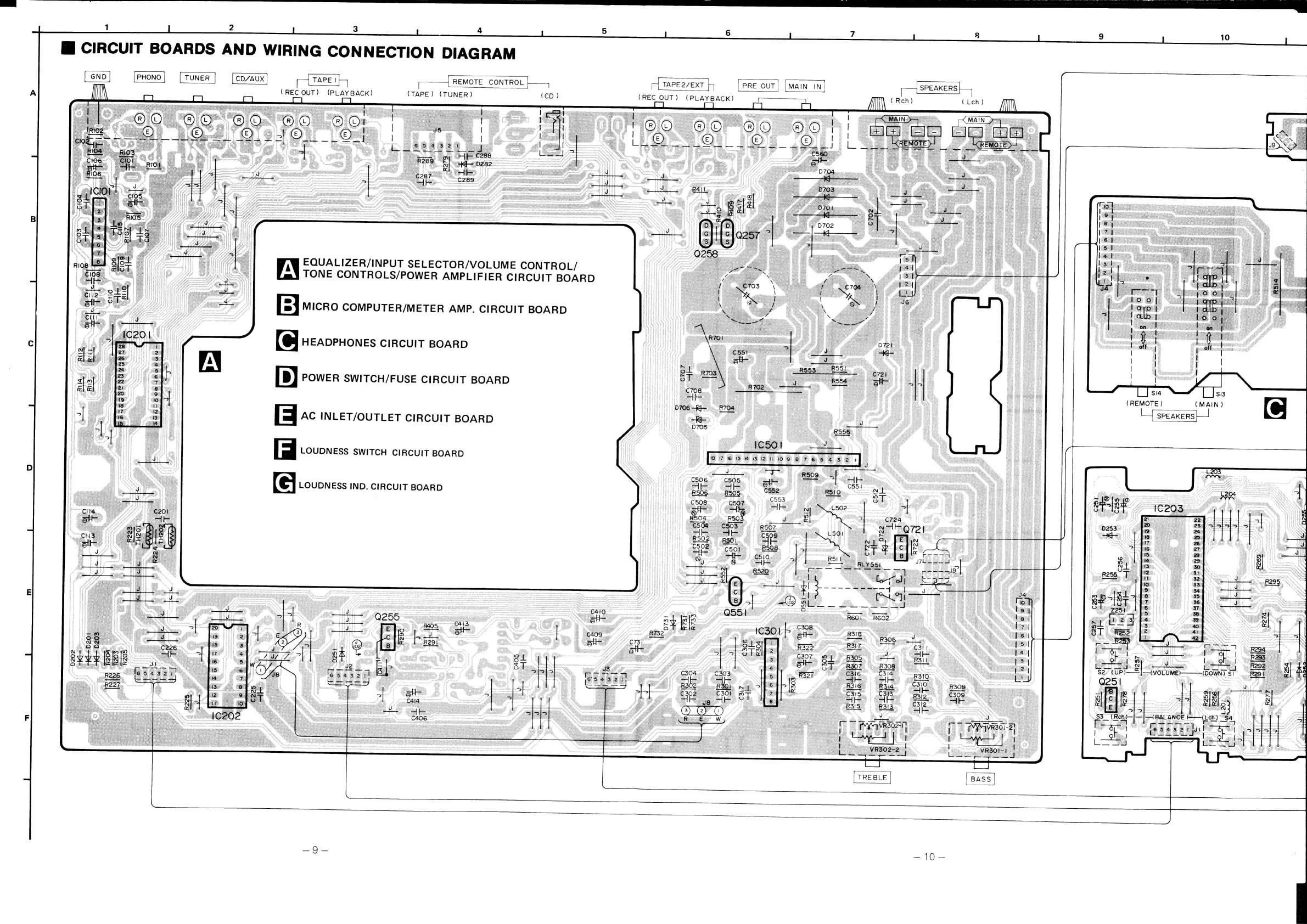
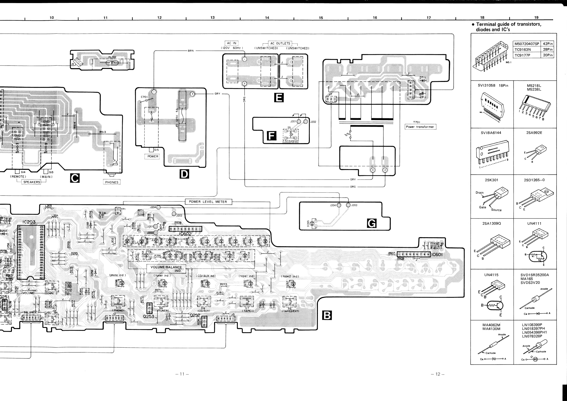
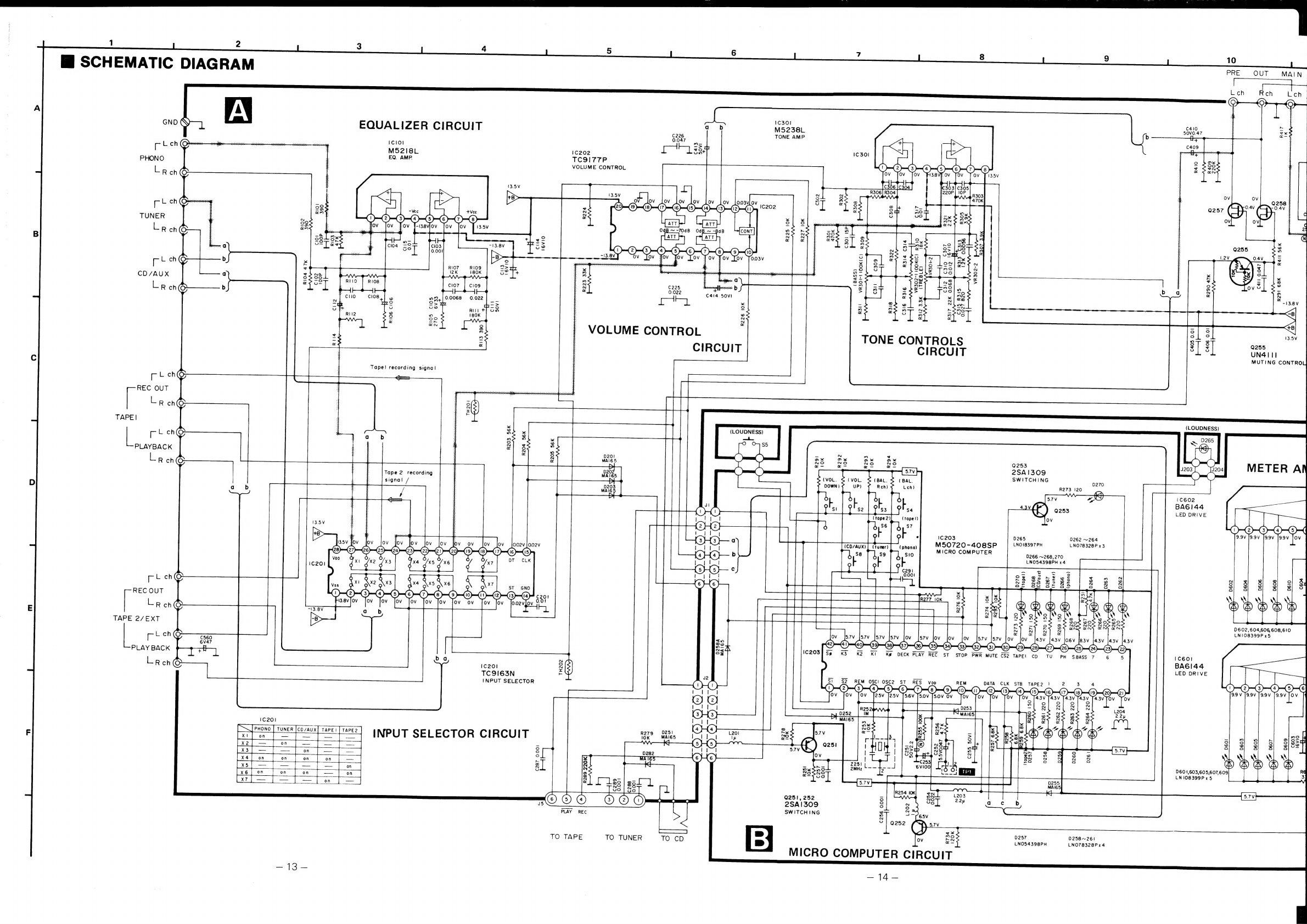
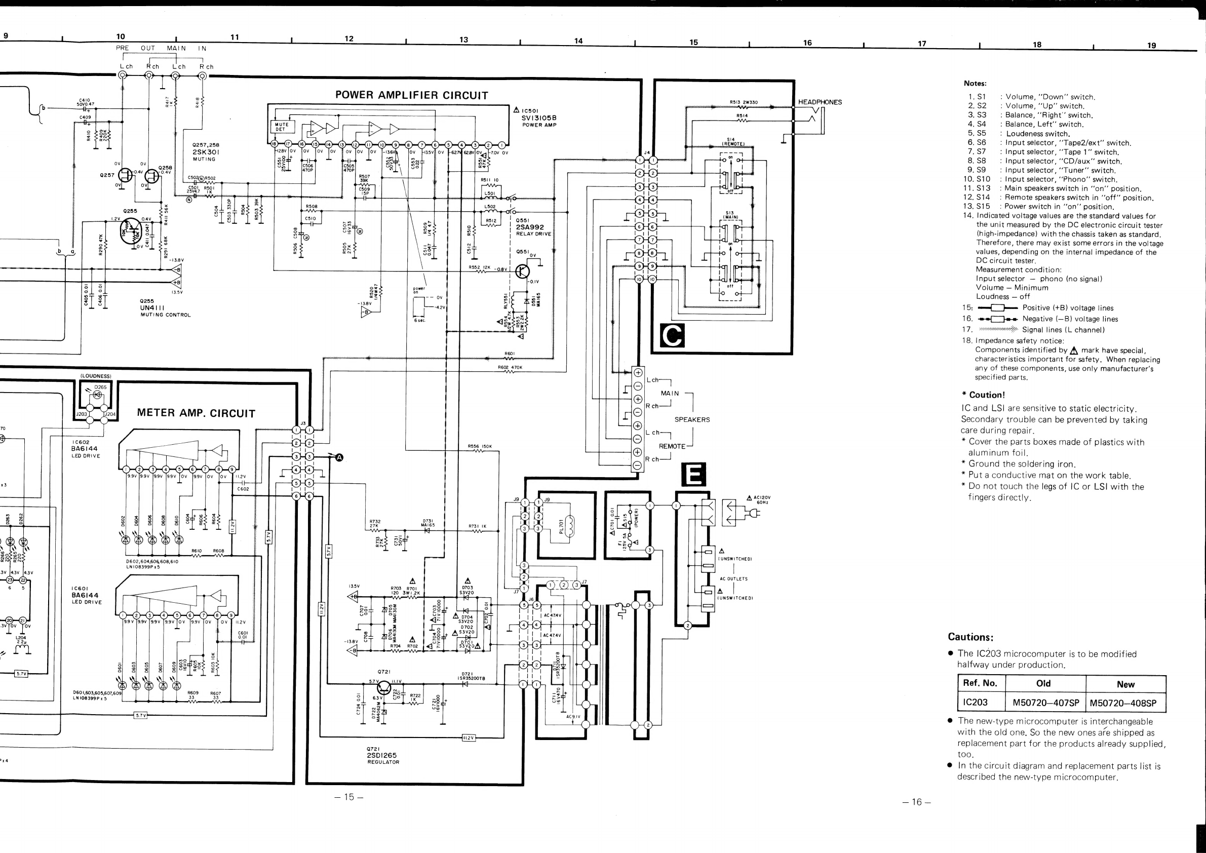
Panasonic SU-373 User manual
Other Panasonic Amplifier manuals

Panasonic
Panasonic RAMSA WP-1200B/G User manual

Panasonic
Panasonic CY-PAD1003N User manual

Panasonic
Panasonic SU-MED640E User manual

Panasonic
Panasonic CY-PA4003N User manual

Panasonic
Panasonic WA-H120N User manual

Panasonic
Panasonic FX-311 Series User manual

Panasonic
Panasonic WP9440 - RAMSA POWER AMPS User manual

Panasonic
Panasonic RAMSA WP-1200 User manual

Panasonic
Panasonic LS-501 C2 Series User manual

Panasonic
Panasonic FX-502 Series User manual

Panasonic
Panasonic WJ300C - SWITCHER/CONTROLLER User manual

Panasonic
Panasonic CY-PA2003W User manual

Panasonic
Panasonic LS-403 User manual

Panasonic
Panasonic FX-501 Series User manual

Panasonic
Panasonic CY-M9054 Operating User manual

Panasonic
Panasonic LS-401 User manual

Panasonic
Panasonic SE-HDV600 User manual

Panasonic
Panasonic FX-501 Series User manual

Panasonic
Panasonic FX-550L Series User manual

Panasonic
Panasonic FX-502 User manual