Panasonic BT-LH1800p User manual

Before attempting to connect, operate or adjust this product, please read these instructions completely.
Model BT-LH1800
P
Model BT-LH1500
P
POWER A B
INPUT SELECT
SOPTION MENU/
EXIT
BLUE
ONLY
PHASE CHROMA BRIGHT
CONTRAST
BT
-
M
ULTIFORMAT
HV
DELAY
ENTER
MENU
Liquid Crystal Video Monitor
Printed in Japan
VQT9921 F0502H@3

2
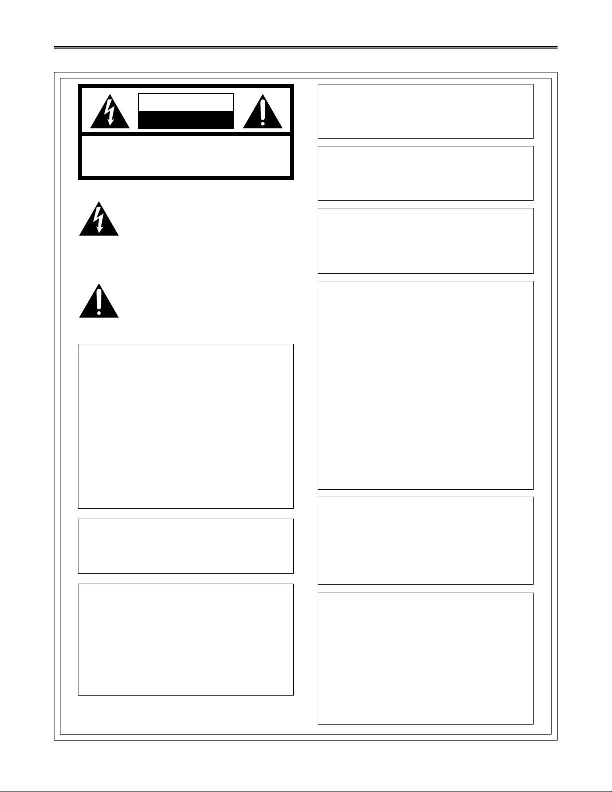
CAUTION: TO REDUCE THE RISK OF ELECTRIC SHOCK,
DO NOT REMOVE COVER (OR BACK).
NO USER-SERVICEABLE PARTS INSIDE.
REFER SERVICING TO QUALIFIED SERVICE PERSONNEL.
RISK OF ELECTRIC SHOCK
DO NOT OPEN
CAUTION
For Your Safety
THIS APPARATUS MUST BE GROUNDED
To ensure safe operation the three-pin plug must be
inserted only into a standard three-pin power outlet
which is effectively grounded through normal house-
hold wiring.
Extension cords used with the equipment must be
three-core and be correctly wired to provide connec-
tion to the ground. Incorrectly wired extension cords
can be extremely hazardous.
The fact that the equipment operates satisfactorily
does not imply that it is grounded, and the installa-
tion is not necessarily safe. For your safety, if in any
doubt about the effective grounding of the equipment
or power outlet, please consult a qualified electrician. CAUTION:
Do not install or place this unit in a bookcase,
built- in cabinet or in another confined space in
order to keep well ventilation condition. Ensure
that curtains and any other materials do not ob-
struct the ventilation condition to prevent risk of
electric shock or fire hazard due to overheating.
CAUTION:
TO REDUCE THE RISK OF FIRE OR SHOCK HAZ-
ARD, REFER MOUNTING OF THE OPTIONAL
UNIT TO AUTHORIZED SERVICE PERSONNEL.The lightning flash with arrowhead symbol,
within an equilateral triangle, is intended to
alert the user to the presence of uninsulated
dangerous voltage within the products en-
closure that may be of sufficient magnitude
to constitute a risk of electric shock to per-
sons.
The exclamation point within an equilateral
triangle is intended to alert the user to the
presence of important operating and main-
tenance (servicing) instructions in the litera-
ture accompanying the appliance.
WARNING:
TO REDUCE THE RISK OF FIRE OR SHOCK HAZ-
ARD, DO NOT EXPOSE THIS EQUIPMENT TO
RAIN OR MOISTURE.
FCC Note:
This device complies with Part 15 of the FCC Rules.
To assure continued compliance follow the attached
installation instructions and do not make any unau-
thorized modifications.
This equipment has been tested and found to comply
with the limits for a Class A digital device, pursuant to
Part 15 of the FCC Rules. These limits are designed
to provide reasonable protection against harmful in-
terference when the equipment is operated in a com-
mercial environment. This equipment generates, uses,
and can radiate radio frequency energy and, if not in-
stalled and used in accordance with the instruction
manual, may cause harmful interference to radio com-
munications. Operation of this equipment in a residen-
tial area is likely to cause harmful interference in which
case the user will be required to correct the interfer-
ence at his own expense.
CAUTION:
TO REDUCE THE RISK OF FIRE OR SHOCK HAZ-
ARD, REFER CHANGE OF THE SWITCH SETTING
INSIDE THE UNIT TO AUTHORIZED SERVICE
PERSONNEL.
1is the safety information.
CAUTION:
TO REDUCE THE RISK OF FIRE OR SHOCK HAZ-
ARD AND ANNOYING INTERFERENCE, USE THE
RECOMMENDED ACCESSORIES ONLY.
CAUTION:
This apparatus can be operated at a voltage in the
range of 100 – 240 V AC.
Voltage other than 120 V is not intended for U.S.A.
and Canada.
CAUTION:
Operation at a voltage other than 120 V AC may re-
quire the use of a different AC plug. Please contact
either a local or foreign Panasonic authorized ser-
vice center for assistance in selecting an alternate
AC plug.
WARNING:
TO REDUCE THE RISK OF FIRE OR SHOCK
HAZARD, KEEP THIS EQUIPMENT AWAY
FROM ALL LIQUIDS-USE AND STORE ONLY
IN LOCATIONS WHICH ARE NOT EXPOSED
TO THE RISK OF DRIPPING OR SPLASHING
LIQUIDS, AND DO NOT PLACE ANY LIQUID
CONTAINERS ON TOP OF THE EQUIPMENT.

3
For Your Safety ........................................... 2
Precautions for Use..................................... 3
Outline ......................................................... 4
Controls and Their Functions ...................... 5
_Front View ........................................... 5
_Rear View............................................ 5
How To Use On Screen Menu..................... 6
_How To Get On Screen Menu ............. 6
_MAIN Menu ......................................... 6
_MARKER ........................................ 6
_VIDEO CONFIG ............................. 7
_SYSTEM CONFIG .......................... 7
_REMOTE CONFIG ......................... 8
_INPUT SELECT .............................. 8
_MAINTENANCE ............................. 9
REMOTE Specifications ............................ 10
Description of MARKER ............................ 11
_Description of Each MARKER........... 11
Troubleshooting......................................... 12
Maintenance Inspection ............................ 12
Specifications ............................................ 13
Precautions for Use
Contents
This product is specially designed for industrial use. So, it must be operated by a person having
technical knowledge.
•The liquid crystal portion is manufactured with highly precise technology. It includes over 99.99% of effective pixels,
but 0.01% or less of pixel missing or fixed lighting (red, blue, green) as well. This is not a sign of malfunction.
• If a still image is displayed for a long time, it may cause temporary generation of afterimage (phosphor burn-in).
(Such afterimage will disappear when an ordinary mobile image is displayed for a while.)
• The response speed and brightness of liquid crystal vary with the ambient temperatures.
• Consult with the authorized service person for the installation.
Be sure to consult with the service person about the installation. Make sure that the wall or ceiling is strong enough to endure the
weight of this unit including the mount fittings. If not strong enough, it may cause accidents such as falling off of the unit and
injuries.
• Do not install the unit in a place exposed to the direct sunlight. It may otherwise deteriorate the cabinet or damage the liquid
crystal acreen.

4
16-1/4z(412)
14-15/16z(379)
8-5/16z(210)
1-9/16z(39)
11-1/2z(291)
3-7/16z(86)
12-1/2z(317)
13-15/16z(353)
12-3/16z(309)
8-5/16z(210)
1-9/16z(39)
3-7/16z(86)
11-1/2z(291)
12-1/2z(317)
BT-LH1800
BT-LH1500
Outline
BT-LH1800 and BT-LH1500 are thin, light-weight wide-view industrial liquid crystal monitors which are respectively
equipped with 18.1-inch and 15-inch screen size liquid crystals.
_Multi-input format compatible
Compatible with HD signal input as well as standard NTSC
signal and PAL signal.
_Wide view angle
Good pictures can be observed in a wide angle range, up/
down and right/left, with a wide-view LCD employed.
_Easy-to-use operation panel
Based on the operation panel of a conventional industrial
monitor, realizing good maneuverability without inconve-
nience.
_Appearance view
_REMOTE terminal
Capable of parallel remote input control by which func-
tions can be selected.
_VESA mount
It is provided with VESA mount. So, it can be installed
onto the ceiling, wall or mount arm.
There are two types of pitch screw holes, 3-15/16zk 3-15/
16z (100 k 100 mm) and 3zk 3z (75 k75 mm).
( ): mm

5
Front View
!@#$ %
POWER A B
INPUT SELECT
S OPTION MENU/
EXIT
BLUE
ONLY
PHASE CHROMA BRIGHT
CONTRAST
M
HV
DELAY
ENTER
MENU
qS
1
2
3
4
5
6
78
9
qR
qS
7, 8, 9to qR are options.
Rear View
Control and Their Functions
!Power switch
This is the main power switch.
With power ON, the upper LED (green) of the switch is
lighted.
@Input select button
This is the signal input select button.
The input line of the button pressed is selected, then the
upper LED (green) is lighted.
A: Line-A (composite input)
B: Line-B (composite input)
S: S-Video (S-video input)
OPTION: Option unit
#Menu select button
Used for menu display, adjustment and setting.
MENU/EXIT:
Push when displaying a menu and getting out
of the menu.
: Push when moving the cursor up/down or se-
lecting an item.
ENTER: Push when getting into a downward menu.
$BLUE ONLY/HV DELAY button
BLUE ONLY: With the button pushed, picture quality can
be adjusted by color lever.
When it is pushed again, the mode returns
to normal display.
HV DELAY: SYNC, blanking, and burst flag can be ob-
served.
Normal, H-Delay, V-delay and HV-Delay are
repeatedly displayed each time when
pushed. It doesn’t work when HD ZOOM is
used.
%Picture adjusting knob
(Hue/chroma/brightness/contrast)
Adjustable with the knob pushed and popped out, and re-
turned to preset value with it pushed in.
When set to a value other than the standard preset value,
the upper LED (amber) of adjusting knob is lighted.
1LINE-A connector
This is the composite input connector A (BNC). (With
through-out type)
2LINE-B connector
This is the composite input connector B (BNC). (With
though-out type)
3S-video input connector
This is the S-video signal input connector. (With though-
out type)
4REMOTE terminal
This is the REMOTE terminal (9-pin D-Sub).
5SIGNAL GND terminal
This is the signal GND terminal.
6AC power input socket
This is the AC power socket. Connect the attached power
cord. (Slip-off preventive fittings attached)
7HD-SDI connector
This is the HD-SDI input connector (BNC). (With active
through-out type) [In use of optional HD SDI INPUT UNIT
(BT-YA300P)]
8SDI connector
This is the SDI input connector (BNC). (With active through-
out type) [In use of optional SDI INPUT UNIT (BT-YA200P)]
9– qR COMPONENT/RGB connector
This is the analog component/RGB input connector (BNC).
(With through-out type)
Also provided with external sync connector. [In use of op-
tional COMPONENT/RGB INPUT UNIT (BT-YA100P)]
qS VESA mount
!
!

6
With MARKER selected, the following menu will appear.
MARKER 16:9
Used to set Marker used when 16:9 signal is displayed.
Set-value (underlined is default value)
4:3 13:9 14:9
95% 93% 88% 80%
OFF
MARKER 4:3
Used to set Marker used when 4:3 signal is displayed.
Set-value (underlined is default value)
95% 93% 88% 80%
OFF
MARKER BACK*1)
Used to make setting for printing out by half tone or black with
respect to external area of 4:3/13:9/14:9 Marker display unit.
Set-value (underlined is default value)
NORMAL HALF BLACK
[GP1]
• PRESET 1
Used to set Marker displayed by MARKER 1 of GPI (remote
control).
Set-value (underlined is default value)
4:3 13:9 14:9
95% 93% 88% 80%
• PRESET 2
Used to set Marker displayed by MARKER 2 of GPI (remote
control).
Set-value (underlined is default value)
4:3 13:9 14:9
95% 93% 88% 80%
*1) MARKER BACK operates only when 4:3/13:9/14:9 MARKER is
displayed by MARKER 16:9. This is not interlocked with MARKER
(MARKER 1 and MARKER 2) control by GPI.
[MAIN]
>MARKER 4
VIDEO CONFIG 4
SYSTEM CONFIG 4
REMOTE CONFIG 4
INPUT SELECT 4
MAINTENANCE 4
[INPUT SIGNAL]
1080/60I
MAIN menu
Main menu includes the following items.
MARKER
Used to make setting for MARKER.
VIDEO CONFIG
Used to set the color temperature, aspect, and monochrome.
SYSTEM CONFIG
Used to set backlight brightness and various status display
and to save/load the set-values.
REMOTE CONFIG
Used to set the pin assignment of REMOTE input terminal.
INPUT SELECT
Used to set the format for each input connector.
MAINTENANCE
Operation time of LCD and backlight is displayed.
[INPUT SIGNAL]
When the format of signal being input is coincidental with the
setting, the type of the signal is displayed. In case the signal
format does not match the setting or the input signal is other
than support, the message will be displayed.
When MENU/EXIT button is pushed, the main menu appears
on the screen.
R
A B
INPUT SELECT
S OPTION MENU/
EXIT
BLUE
ONLY
PHASE CHROMA
B
HV
DELAY
ENTER
MENU
[MARKER]
>MARKER 16:9 OFF
MARKER 4:3 OFF
MARKER BACK NORMAL
[GPI]
PRESET1 80%
PRESET2 80%
MARKER menu
MARKER
MAIN menu
How To Get On Screen Menu
How To Use On Screen Menu

7
[VIDEO CONFIG]
>COLOR TEMP D65
SHARPNESS H 3
SHARPNESS V 3
I-P MODE MODE2
MONO OFF
SD ASPECT 4:3
HD ZOOM NORMAL
VIDEO CONFIG menu
VIDEO CONFIG SYSTEM CONFIG
With SYSTEM CONFIG selected, the following menu will
appear.
BACKLIGHT
Used to adjust the brightness of backlight.
Set-value (underlined is default value)
0 –63 (BT-LH1800)
0 –32 –63 (BT-LH1500)
POSITION
Used to set the display position of on screen menu.
Set-value (underlined is default value)
CENTER (center of screen), LT (top left of screen),
RT (top right of screen), RB (bottom right of screen),
LB (bottom left of screen).
ERROR MESSAGE
Used to select whether or not displaying transmitting system
error of SDI and HD-SDI. If an error is generated, “CRCC
ERROR”will be displayed.
Set-value (underlined is default value)
ON OFF
STATUS DISPLAY
Used to set the information display in case of input change
or the format display in case of signal input.
Set-value (underlined is default value)
CONTINUE 3SEC OFF OFF
CONTROL LOCK
All menu items other than CONTROL LOCK and front panel operations
other than power switch are locked (invalidated). Even when locked, it
returns to preset value with picture adjusting knob pushed in.
Set-value (underlined is default value)
ON OFF
SETUP
•LOAD
Used to read in the set-value being saved.
“FACTORY”reads in the factory-adjusted value.
Set-value (underlined is default value)
FACTORY USER1*1) USER2*1)
USER3*1) USER4*1) USER5*1)
•SAVE
Current set-values can be saved up to 5.
Set-value (underlined is default value)
USER1 USER2 USER3
USER4 USER5
*1) The contents of USER1 –USER5 and FACTORY are same at
the time of delivery from the factory.
[SYSTEM CONFIG]
>BACKLIGHT 63
POSITION CENTER
ERROR MESSAGE ON
STATUS DISPLAY CONTINUE
CONTROL LOCK OFF
[SET UP]
LOAD FACTORY
SAVE USER1
SYSTEM CONFIG menu
How To Use On Screen Menu
With VIDEO CONFIG selected, the following menu will appear.
COLOR TEMP
Used to set the color temperature
Set-value (underlined is default value)
USER 0 –63*1) D93 D65
SHARPNESS H
Used to set the sharpness in horizontal direction.
Set-value (underlined is default value)
0 –15*2) Default value
3 (HD) 12 (SD) (BT-LH1800)
2 (HD) 2 (SD) (BT-LH1500)
SHARPNESS V
Used to set the sharpness setting in vertical direction.
Set-value (underlined is default value)
0 –15*2) Default value
3 (HD) 3 (SD) (BT-LH1800)
2 (HD) 2 (SD) (BT-LH1500)
I-P MODE
Used to set the mode for IP change.
Set-value (underlined is default value)
MODE1 MODE2
MONO
Used to make setting for mono-chrome display.
Set-value (underlined is default value)
ON OFF
SD ASPECT
Used to set the aspect ratio in case of SD signal input.
Select REMOTE when executing external change by REMOTE terminal.
Set-value (underlined is default value)
REMOTE 16:9 4:3
HD ZOOM
Enlarged 4:3 is displayed by PAN&SCAN in case of 1080I,
1035I, 720P signal input.
Select REMOTE when executing external change by REMOTE
terminal.
This item is displayed only when HD SDI input unit or compo-
nent/RGB input unit is installed.
Set-value (underlined is default value)
4:3 NORMAL REMOTE
*1) By user setting, it is possible to change the color temperature in
64 stages from 0 (around 3000K) to 63 (around 9300K).
*2) Sharpness value has a set-value and is displayed for each of in-
put signal (HD/SD)

8
With INPUT SELECT selected, the following menu will ap-
pear.
LINE A, B/S-VIDEO
Used to set the input format of LINE A, B/S-VIDEO.
Set-value (underlined is default value)
AUTO NTSC PAL
NON-STANDARD
Used to display a signal not in conformity with the broadcast-
ing standard in selection of LINE A, LINE B, S-VIDEO.
Set-value (underlined is default value)
OFF ON
REMOTE CONFIG
[REMOTE CONFIG]
>GPI1 UNDEF
GPI2 UNDEF
GPI3 UNDEF
GPI4 UNDEF
GPI5 UNDEF
GPI6 UNDEF
GPI7 UNDEF
GPI8 UNDEF
REMOTE CONFIG menu
INPUT SELECT
[INPUT SELECT]
>[LINE A,B/S-VIDEO] AUTO
NON-STANDARD OFF
INPUT SELECT menu
[INPUT SELECT]
>[LINE A,B/S-VIDEO] AUTO
NON-STANDARD OFF
[HD-SDI] AUTO
INPUT SELECT HD-SDI menu
With REMOTE CONFIG selected, the following menu will
appear.
GPI1–GPI8
Used to set the pin assignment of REMOTE control terminal.
The settable items are same for each terminal.
For each function of set-value, refer to the “REMOTE specifi-
cations.”
Set-value (underlined is default value)
UNDEF
MARKER1 ON/OFF
MARKER2 ON/OFF
MARKER HALF*1)
MARKER BLACK*1)
INPUT SEL A
INPUT SEL B
INPUT SEL S
INPUT SEL OP
SD ASPECT*2)
HD ZOOM*3)
BACKLIGHT OFF
*1) MARKER HALF and MARKER BLACK are effective only when
MARKER1 and MARKER2 are used with 4:3/13:9/14:9 displayed.
*2) When using SD ASPECT, set SD ASPECT to REMOTE by VIDEO
CONFIG menu.
*3) When using HD ZOOM, set HD ZOOM to REMOTE by VIDEO
CONFIG menu. HD ZOOM is effective only in case of 1080I, 1035I,
720P signal input.
HD-SDI
Used to set the input format of HD-SDI.
Set-value (underlined is default value)
AUTO 1080/60I*1) 1080/50I
1080/24psF*2) 1035/60I*1)
720/60P*3)
*1) 1080/60I and 1035/60I are different with respect to the display
size and the matrix used.
Select 1080/60I and 1035/60I even in case of 1080/59.94I and
1035/59.94I signal input.
The status will be correctly displayed on the screen.
*2) Select 1080/24psF even in case of 1080/23.98psF signal input.
The status will be correctly displayed on the screen.
*3) Select 720/60P even in case of 720/59.94P signal input.
The status will be correctly displayed on the screen.
Menu for option unit is further added for each
type of option unit fitted on the rear panel.
_HD SDI input unit installed [BT-YA300P]
How To Use On Screen Menu

9
INPUT SELECT (continued)
[INPUT SELECT]
>[LINE A,B/S-VIDEO] AUTO
NON-STANDARD OFF
[SDI] AUTO
INPUT SELECT SDI menu
INPUT SELECT (continued)
[INPUT SELECT]
>[LINE A,B/S-VIDEO] AUTO
NON-STANDARD OFF
[YPbPr/RGB] YPbPr
YPbPr AUTO
COMPONENT LEVEL SMPTE
[RGB] AUTO
RGB-SYNC EXT
INPUT SELECT YPbPr/RGB menu
MAINTENANCE
[MAINTENANCE]
RUNNING TIME
OPERATION 0H
LCD 0H
BACKLIGHT 0H
FAN 0H
MAINTENANCE menu
_SDI input unit mounted [BT-Y200P]
SDI
Used to set the input format of SDI.
Set-value (underlined is default value)
AUTO 480/60I*1) 576/50I
*1) 480/59.94I signal is displayed as 480/60I.
_Component/RGB input unit mounted [BT-YA100P]
YPbPr/RGB
Used to select the input of YPbPr/RGB.
Set-value (underlined is default value)
YPbPr RGB
YPbPr
Used to select the format in case of YPbPr input.
Set-value (underlined is default value)
AUTO*1) 1080/60I*2) 1080/50I
1080/24psF 1035/60I*2) 720/60P*3)
576/50I 480/60P*4) 480/60I*4)
COMPONENT LEVEL (480/60I only)
Used to select the input level of component. Select SMPTE
for the signal from MII VTR, and B75 for the signal of 7.5%
setup of Betacam VTR.
Set-value (underlined is default value)
SMPTE B75
RGB
Used to select the format in case of RGB input.
Set-value (underlined is default value)
AUTO*1) 1080/60I*2) 1080/50I
1035/60I*2) 720/60P*3) 576/50I
480/60P*4) 480/60I*4)
RGB-SYNC (When RGB is input.)
Used to select Ext. Sync/GREEN-On-SYNC.
Set-value (underlined is default value)
EXT G-ON
*1) In AUTO setting, the settings of display size, status display, and
matrix are same as for 1080I even in case of 1035I input. When
desired to use 1035I setting, set it to 1035/60I.
*2) 1080/60I and 1035/60I are different with respect to the display
size and the matrix used. Select 1080/60I and 1035/60I even in
case of 1080/59.94I and 1035/59.94I signal input. The status will
be correctly displayed on the screen.
*3) Select 720/60P even in case of 720/59.94P signal input. The sta-
tus will be correctly displayed on the screen.
*4) 480/59.94I and 480/59.94P signals are displayed as 480/60I and
480/60P.
With MAINTENANCE selected, the following menu will ap-
pear.
OPERATION
The total operation time of the whole LCD monitor is displayed.
LCD
The operation time of the LCD panel is displayed.
BACKLIGHT
The operation time of the backlight is displayed.
FAN
The operation time of the exhaust fan is displayed.
How To Use On Screen Menu

10
_GPI hard specification
8 inputs (refer to D-SUB 9-pin terminal)
_ON/OFF operation
Each terminal of REMOTE operates its assigned function accord-
ing to the setting with GND (Pin 5) shorted (ON) or opened (OFF).
_How to assign the function to each terminal
The assignment to each terminal can be freely executed by
the On Screen Menu.
(Refer to “How To Use On Screen Menu”.)
Contents
GPI 1–GPI 4
GND
GPI 5–GPI 8
Pin No.
Pin 1–Pin 4
Pin 5
Pin 6–Pin 9
[REMOTE CONFIG]
>GPI1 UNDEF
GPI2 UNDEF
GPI3 UNDEF
GPI4 UNDEF
GPI5 UNDEF
GPI6 UNDEF
GPI7 UNDEF
GPI8 UNDEF
REMOTE CONFIG menu
GPI1
GPI5
MARKER 1
GPI1
GPI5
MARKER 1
1
23
4
5
678
9
REMOTE Specifications
_Priority order of each function
•When MARKER 1 and MARKER 2 are simultaneously turned
ON, the priority is given to MARKER 1.
•4:3/13:9/14:9 MARKER is displayed only when 16:9 is dis-
played. 95%/93%/88%/80% MARKER is automatically
changed in size according to 4:3 and 16:9 display.
•When MARKER HALF and MARKER BLACK are simulta-
neously turned ON, the priority is given to BLACK.
•In case same setting is assigned to a plurality of terminals,
ON operation continues until all terminals turn OFF. (Level
operation terminal only)
Ex.) Operation with GPI1 and GPI5 set to MARKER 1:
•In case of edge operation terminal, the priority is given to the
terminal turned ON later.
•In case the operation is impossible, REMOTE terminal will
not operate. (Refer to the example below.)
1) 4:3/13:9/14:9 MARKER display in 4:3 display.
2) HD ZOOM selection in case of a signal other than 1080I,
1035I, 720P signal.
3) SD aspect selection in case of HD.
4) INPUT OP selection when option unit is not installed.
*1) Operating conditions
Level operation: It operates only while GPI terminal is shorted to
GND.
Edge operation: It operates at edge of the fall when shorted to
GND.
*2) MARKER displayed by PRESET 1 and PRESET 2 is the one se-
lected by the menu for MARKER setting. (It is set by [MARKER]-
[GPI]PRESET 1 and PRESET 2 in the menu.)
*3) MARKER HALF and MARKER BLACK are effective only when
4:3/13:9/14:9 MARKER is displayed by using MARKER 1 and
MARKER 2.
(For the detail, refer to the “Description of MARKER.”)
All initial
states are
undefined
(UNDEF).
Function
Undefined (terminal assignment
not defined)
ON/OFF of marker selected by
PRESET1*2)
ON/OFF of marker selected by
PRESET2*2)
Background of marker being
displayed is set to HALF.
Background of marker being
displayed is set to BLACK.
Input system is changed to A.
Input system is changed to B.
Input system is changed to S.
Input system is changed to
OPTION.
Display change in SD,
16:9 (ON)/4:3 (OFF)
Display change in HD (1080I,
1035I, 720P), 4:3 (ON) enlarged/
16:9 (OFF)
Brightness of backlight is set to
minimum.
[List of Assigning Functions]
Assignment items
UNDEF
MARKER1 ON/OFF
MARKER2 ON/OFF
MARKER HALF
MARKER BLACK
INPUT SEL. A
INPUT SEL. B
INPUT SEL. S
INPUT SEL. OP
SD ASPECT
HD ZOOM
BACKLIGHT OFF
Operating
conditions*1)
––––
Level operation
Level operation
Level operation
Level operation
Edge operation
Edge operation
Edge operation
Edge operation
Level operation
Level operation
Level operation

11
[MARKER]
>MARKER 16:9 OFF
MARKER 4:3 OFF
MARKER BACK NORMAL
[GPI]
PRESET1 80%
PRESET2 80%
Description of Each MARKER
4:3 MARKER (vertical line only) 14:9 MARKER (vertical line only)
13:9 MARKER (vertical line only)
SAFETY ZONE 95% SAFETY ZONE 93%
SAFETY ZONE 88% SAFETY ZONE 80%
SAFETY ZONE 95% SAFETY ZONE 93%
SAFETY ZONE 88% SAFETY ZONE 80%
Description of MARKER
_Select the MARKER displayed by using the on screen
menu.
MARKER 16:9
MARKER display selection in case of 16:9 signal input.
Set-value (underlined is default value)
4:3/13:9/14:9/95%/93%/88%/80%/OFF
MARKER 4:3
MARKER display selection within HD ZOOM in case of 4:3
signal input and 108I, 1035I, 720P signal input.
Set-value (underlined is default value)
95%/93%/88%/80%/OFF
MARKER BACK
Selection of MARKER background
Set-value (underlined is default value)
NORMAL/HALF/BLACK
[GPI]
•PRESET 1
Selection of MARKER used in MARKER 1 of GPI.
(Refer to “REMOTE specification.”)
•PRESET 2
Selection of MARKER used in MARKER 2 of GPI.
(Refer to “REMOTE specification.”)
_MARKER for 16:9 (continued)
(Displayed in case of HD, and SD of aspect ratio 16:9)
_MARKER for 16:9
(Displayed in case of HD, and SD of aspect ratio 16:9)
* Shaded areas are portions
where the brightness var-
ies with Half, Black and
Normal selected.
_MARKER for 4:3 (displayed in case of SD of aspect
ratio 4:3)
* SAFETY ZONE MARKER is only the inside line. Also, Half and
Black cannot be set.

12
Every 30,000H
¥
(replace)
¥
(replace)
¥
Maintenance inspections are necessary for the user to use
the video equipment safely and to keep the function in good
condition at all times through periodical and appropriate main-
tenance.
In order to make the most of the function of this unit, be sure
to carry out the maintenance inspections.
1. Necessity of periodical maintenance services
Backlight as a light source and heat exhaust fan motor are
used for the liquid crystal monitor.
These parts (consumable) are deteriorated with lapse of
time and may cause worsening of the performance or gen-
eration of trouble.
Accordingly, besides the conventional after-services per-
formed in case of trouble, it is very important to perform
general services, that is, maintenance services in order to
prevent accidents or trouble due to deterioration of con-
sumable parts, keeping the equipment in normal condition.
2. Standard maintenance time and execution items
The following maintenance execution time is set as a stan-
dard and not identical with individual life time. Also, note
that the deterioration time varies with the using environ-
ment and method.
Check and adjust the following points. If it doesn’t work, con-
sult with your dealer.
•Operation key does not work.
Check that the control lock is not “ON.”
#To unlock it, set the CONTROL LOCK in the SYSTEM
CONFIG menu to “OFF.”
(See page 7.)
Maintenance InspectionTroubleshooting
1) “Main parts adjustment, general adjustment”of No.3 above in-
cludes the adjustment of gamma characteristics.
2) The above adjustment of gamma characteristics is necessary in
backlight replacement.
No.
1
2
3
Part name
Backlight
Fan motor
Main parts adjustment,
general adjustment
Q’ty
1
1
1
Periodic maintenance spec.
and time (H)
Every 10,000H
–––
¥
(replace)
¥

13
Specifications
•Option 1
SDI input unit [BT-YA200P]
SDI input/output: Input; BNC k1
Buffer output; BNC k1
Signal format: 480/59.94I, 576/50I
(Component Serial Digital)
•Option 2
HD SDI input unit [BT-YA300P]
HD-SDI input/output:
Input; BNC k1
Buffer output; BNC k1
Signal format: 1080/60I 1035/60I
1080/59.94I 1035/59.94I
1080/50I 720/60P
1080/24psF 720/59.94P
1080/23.98psF
•Option 3
Component/RGB input unit [BT-YA100P]
Analog RGB+EXT-Sync*/YPbPr Input/output:
Input; BNC k4
Through output; BNC k4
(75 ™auto termination)
Signal format: RGB
1080/60I 720/60P
1080/59.94I 720/59.94P
1080/50I 576/50I
1035/60I 480/59.94P
1035/59.94I 480/59.94I
YPbPr
1080/60I 1035/60I
1080/59.94I 1035/59.94I
1080/50I 720/60P
1080/24psF 720/59.94P
1080/23.98psF 575/50I
480/59.94P
480/59.94I
*EXT-Sync is effective only for RGB.
•Option 4
Rack-mount adapter [BT-MA1800P]
Rack-mount adapter [BT-MA1500P]
Weight and dimensions shown are approximate.
Specifications are subject to change without notice.
Dimensions: 16-1/4 (W) k 14-15/16 (H) k 3-7/16 (D)
inches
(412 k379 k 86 mm)
(BT-LH1800)
13-15/16 (W) k 12-3/16 (H) k 3-7/16 (D)
inches
(353 k309 k86 mm)
(BT-LH1500)
*Depth with option installed is 4-3/8 inches
(110mm) for both models.
Weight: 18.26 lbs (8.3kg) (main body only, BT-
LH1800)
13.86 lbs (6.3kg) (main body only, BT-
LH1500)
Operating temp.: i41xF to i95xF (i5xC to i35xC)
Storage temp.: i14xF to i104xF (j10xC to i40xC)
Operating humidity:
20%–80% (No condensation)
Storage humidity: 10%–90% (No condensation)
_Panel
Size: 18 type (BT-LH1800)
15 type (BT-LH1500)
Aspect ratio: 5:4 (BT-LH1800)
4:3 (BT-LH1500)
Pixels: 1280 k 1024 (BT-LH1800, SXGA)
1024 k768 (BT-LH1500, XGA)
Color display: Approx. 1,6770,000 colors
View angle: 170xup/down, 170xright/left
_Input/output connector
Standard video input
Composite: 2 systsm, BNC k2
(One is through-out.)
S-VIDEO: 1 system, S-video connector k2
(One is through-out.)
Signal format: 480/59.94I (NTSC)
576/50I (PAL)
Option input: Analog component, SDI, HD-SDI
One from input unit can be fitted.
_Parallel remote input
8-input (Dsub 9-pin)
MARKER ON/OFF: Marker ON/OFF
MARKER BACK: Masking of Marker background
Input Select: Selection of video input system
4:3/16:9 display: SD ASPECT, HD ZOOM
BACKLIGHT OFF: Backlight brightness minimum
*Pin assignment is selected by menu.
_Standard accessories
Power cord (1)
VESA fitting (attached to main body) (1)
Instruction manual (1)
_General
Power supply: 100 V –240 V AC, 50 –60 Hz
Power conumption:0.95 A –0.40 A (BT-LH1800)
0.66 A –0.31 A (BT-LH1500)
1is the safety information.

PANASONIC BROADCAST & TELEVISION SYSTEMS COMPANY
UNIT COMPANY OF MATSUSHITA ELECTRIC CORPORATION OF AMERICA
Executive Office:
One Panasonic Way 4E-7, Secaucus, NJ 07094 (201) 348-7000
EASTERN ZONE
One Panasonic Way 4E-7, Secaucus, NJ 07094 (201) 348-7621
Southeast Region:
1225 Northbrook Parkway, Ste 1-160, Suwanee, GA 30024 (770) 338-6835
Central Region:
1707 N Randall Road E1-C-1, Elgin, IL 60123 (847) 468-5200
WESTERN ZONE:
3330 Cahuenga Blvd W., Los Angeles, CA 90068 (323) 436-3500
Government Marketing Department:
52 West Gude Drive, Rockville, MD 20850 (301) 738-3840
Broadcast PARTS INFORMATION & ORDERING:
9:00 a.m. –5:00 p.m. (EST) (800) 334-4881/24 Hr. Fax (800) 334-4880
Emergency after hour parts orders (800) 334-4881
TECHNICAL SUPPORT:
Emergency 24 Hour Service (800) 222-0741
Panasonic Canada Inc.
5770 Ambler Drive, Mississauga, Ontario L4W 2T3 (905) 624-5010
Panasonic de Mexico S.A. de C.V.
Av angel Urraza Num. 1209 Col. de Valle 03100 Mexico, D.F. (52) 1 951 2127
Panasonic Sales Company
Division of Matsushita Electric of Puerto Rico Inc.
San Gabriel Industrial Park, 65th Infantry Ave., Km. 9.5, Carolina, Puerto Rico 00630 (787) 750-4300
This manual suits for next models
1
Table of contents
Other Panasonic Baby Monitor manuals

Panasonic
Panasonic VL-W605 User manual

Panasonic
Panasonic KX-HN3001 User manual

Panasonic
Panasonic KX-HN3001W User manual

Panasonic
Panasonic KX-HNC301 User manual

Panasonic
Panasonic WV-BM90 User manual

Panasonic
Panasonic KX-HN3051C User manual

Panasonic
Panasonic KX-HN1032 User manual

Panasonic
Panasonic KX-HN4001 User manual