manuals.online logo
Brands
  1. Home
  2. •
  3. Brands
  4. •
  5. Panasonic
  6. •
  7. DVD Player
  8. •
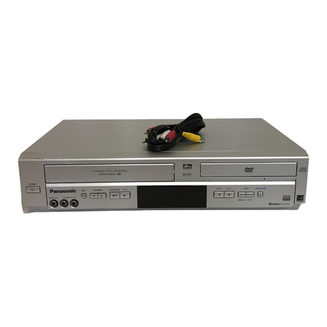
  9. Panasonic PVD734S - DVD/VCR DECK User manual

Panasonic PVD734S - DVD/VCR DECK User manual

ORDERNO.MKE0309803C1
B3
DVDVIDEO PLAYER/ VIDEO CASSETTEREOCRDER
PV-D734S / PV-D744S
ORIGINALMFR'SVERSIONA
1. CAUTION
THIS DIGITALVIDEOPLAYEREMPLOYS ALASERSYSTEM.
TOENSURE PROPERUSE OFTHIS PRODUCT, PLEASE READTHIS SERVICE MANUALCARE-
FULLYAND RETAINFORFUTURE REFERENCE. SHOULDTHE UNITREQUIRE MAINTENANCE,
CONTACTANAUTHORIZEDSERVICE LOCATION-SEE SERVICE PROCEDURE.
USE OFCONTROLS, ADJUSTMENTS ORTHE PERFORMANCE OFPROCEDURES OTHERTHAN
THOSE SPECIFIEDHEREINMAYRESULTINHAZARDOUS RADIATIONEXPOSURE.
TOPREVENTDIRECTEXPOSURE TOLASERBEAM, DONOTTRYTOOPENTHE ENCLOSURE.
VISIBLE LASERRADIATIONMAYBE PRESENTWHENTHE ENCLOSURE IS OPENED. DONOT
STARE INTOBEAM.
1
2. IMPORTANTSERVICE SAFETYINFORMATION
Operating thereceiveroutsideofitscabinetor withitsback removedinvolves ashock hazard.
Workon these modelsshouldonlybeperformedbythose who arethoroughlyfamiliarwith
precautionsnecessarywhenworking on high voltageequipment.
Exercise carewhenservicing thischassiswithpowerapplied. ManyBplusand high voltageRF
terminalsareexposedwhich, ifcarelesslycontacted, cancause seriousshock or resultin
damagetothechassis.
Maintaininterconnecting ground leadconnectionsbetweenchassis, escutcheon, picturetube
dagand tunerclusterwhenoperating thechassis.
These receivershave a"polarized" AClinecord. TheACplug isdesignedtofitintostandard AC
outletsinonedirection only. Thewidebladeconnectstothe"ground side" and thenarrowblade
connectstothe"hotside" oftheACline. Thisassures thattheTV receiverisproperlygrounded
tothehouse wiring. Ifanextension cord mustbeused, make sureitisofthe"polarized" type.
Since thechassisofthisreceiverisconnectedtoonesideoftheACsupplyduring operation,
service shouldnotbeattemptedbyanyonenotfamiliarwiththeprecautionsnecessarywhen
working on these types ofequipment.
Whenitisnecessarytomake measurementsor testswithACpowerappliedtothereceiver
chassis, anIsolation Transformermustbeusedas asafetyprecaution and topreventpossible
damagetotransistors. TheIsolation TransformershouldbeconnectedbetweentheTV linecord
plug and theACpoweroutlet.
CertainHV failures canincrease X-ray radiation.ReceiversshouldnotbeoperatedwithHV levels
exceeding thespecifiedrating for theirchassistype. Themaximum operating HV specifiedfor
thechassisusedinthese receiversis22kV±1.0kVatzero beam currentwithalinevoltageof120V
AC. Highervoltagemay alsoincrease thepossibilityoffailureintheHV supply.
Itisimportanttomaintainspecifiedvalues ofall componentsinthehorizontal and high voltage
circuitsand anywhereelse inthereceiverthatcouldcause arise inhigh voltage, or operating
supplyvoltages. Nochanges shouldbemadetotheoriginal design ofthereceiver.
Componentsshownintheshadedareas on theschematicdiagram and/or identifiedbyinthe
replacementpartslistshouldbereplacedonlywithexactfactoryrecommendedreplacement
parts. Theuse ofunauthorizedsubstitutepartsmay createshock, fire, X-ray radiation, or other
hazards.
Todeterminethepresence ofhigh voltage, use anaccuratehigh impedance HV meterconnected
betweenthesecond anodeleadand theCRTdaggrounding device. Whenservicing theHigh
VoltageSystem, remove staticcharges from itbyconnecting a10kohm resistor inseries withan
insulatedwire(suchas atestprobe)betweenthepicturetubedagand 2nd anodelead(have AC
linecord disconnectedfrom ACsupply).
Thepicturetubeusedinthisreceiveremploys integral implosion protection. Replace withatube
ofthesametypenumberfor continuedsafety. Donotlift picturetubebytheneck. Handlethe
picturetubeonlywhenwearing shatterproofgogglesand afterdischarging thehigh voltage
completely. Keepotherswithoutshatterproofgoggles away.
2
Whenremoving springsor spring mountedpartsfrom thetuner, tunerclusteror chassis,
shatterproofgoggles mustbeworn. Keepotherswithoutshatterproofgoggles away.
Beforereturning thereceivertotheuser, perform thefollowing safetychecks:
1. Inspect all leaddress tomake certainthat leadsarenotpinchedor
that hardwareisnotlodgedbetweenthechassisand othermetal
parts inthereceiver.
2. Replace all protectivedevices suchas nonmetalliccontrol knobs,
insulating fishpapers, cabinet backs, adjustmentand compartment
coversorshields, isolation resistor-capacitornetworks,
mechanical insulators, etc.
3. To besurethat no shock hazardexists, acheck forthepresence
ofleakagecurrentshouldbemadeat eachexposedmetal part
having areturnpathtothechassis(antenna, cabinet metal, screw
heads, knobsand/orshafts, escutcheon,etc.)inthefollowing
manner.
Plug theAClinecord directlyintoa120V ACreceptacle.
(Donotuse anIsolation Transformerduring these checks.)All checks mustberepeatedwiththe
AClinecord plug connection reversed. (Ifnecessary, anonpolarizedadapterplug mustbeused
onlyfor thepurpose ofcompleting these checks.)
Ifavailable, measurecurrentusing anaccurateleakagecurrenttester. Anyreading of0.35mAor
moreisexcessive and indicates apotential shock hazard whichmustbecorrectedbefore
returning thereceivertotheowner.
Ifareliableleakagecurrenttesterisnotavailable, thisalternatemethod ofmeasurementshould
beused.Using twoclipleads, connecta1500 ohm, 10 watt resistor paralleledbya0.15 F
capacitor inseries withaknownearthground,suchas awaterpipeor conduitand themetal part
tobechecked. Use aVTVMorVOMwith1000 ohmspervolt, or higher, sensitivitytomeasurethis
ACvoltagedrop across theresistor. Anyreading of0.35 voltRMS or moreisexcessive and
indicatesa potential shock hazard whichmustbecorrectedbeforereturning thereceivertothe
owner.
3. IMPORTANTSAFEGUARDS
4. TAPE REMOVALMETHODATNO POWER SUPPLY
1. RemovetheTop Cabinet, FrontCabinet and DVDBlock. (Referto
item1oftheDISASSEMBLYINSTRUCTIONS.)
3
2. Removethescrew 1oftheDeck Chassisand removetheLoading
Motor. (Referto Fig. 2 )
3. Rotate thePinchRollerCaminthedirection ofthearrow byhand
toslackentheVideoTape.
4. Rotate theClutchAss'yeitherofthederectionstowind theVideo
TapeintheCassette Case.
5. Repeat theabovestep3~4. Thentake outtheVideoCassette from
theDeck Chassis. Becareful nottoscratchon thetape.
Fig. 1
Fig. 2
5. DISC REMOVALMETHODATNO POWER SUPPLY
1. RemovetheTop Cabinet and FrontCabinet.(Refertoitem1ofthe
DISASSEMBLYINSTRUCTIONS.)
2. SlidetheRack Loading (White) towardthearrow direction by
using aminusdrivertorelease thelock. (Referto Fig. 1 )
3. Draw theTray.
Fig. 1
4
6. PARENTALCONTROL- RATING LEVEL
4DIGITPASSWORD CANCELLATION
Ifthestored4digitpassword intheRating Level menu needstobecancelled, please followthe
stepsbelow.
1. TurnUnitON.
2. Press and holdthe'7'keyon theremote control unit.
3. Simultaneouslypress and holdthe'STOP'keyon thefrontpanel.
4. Holdbothkeysformorethan3seconds.
5. TheOnScreenDisplaymessage'PASSWORD CLEAR' will appear.
6. The4digitpasswordhas now beencleared.
7. GENERALSPECIFICATIONS
8. ABOUTLEADFREE SOLDER (PbF)
Distinction ofPbF PCB:
PCBs(manufactured)using leadfree solderwill have aPbF stampor printing on thePCB.
(Please refertofigures.)
5
Caution:
-Pbfree solderhas ahighermelting pointthanstandardsolder;
Typicallythemelting pointis50°F~70°F(30°C~40°C)higher.
Please use asoldering iron withtemperaturecontrol and adjust it
to700°F±20°F(370°C±10°C).
Incase ofusing high temperaturesoldering iron, please becarefull
nottoheat too long.
-Pbfree solderwill tend tosplashwhenheatedtoo high (about
1100°F/ 600°C).
-All products withtheprintedcircuitboardwithPbF stampor
printing must beservicedwithleadfree solder.
Whensoldering orunsoldering, completelyremoveall ofthe
solderfromthepinsorsolderarea, and besuretoheat the
soldering points withtheleadfree solderuntil itmelts sufficiently.
Recommendations
Recommendedleadfree soldercomposition isSn96.5Ag3.0Cu0.5.
9. DISASSEMBLYINSTRUCTIONS
9.1. REMOVALOFMECHANICALPARTSAND P.C. BOARDS
9.1.1. TOP CABINETAND FRONTCABINET(Referto Fig. 1-1 )
1. Removethe5screws .
2. RemovetheTop Cabinet inthedirection ofarrow (A).
3. Disconnect thefollowing connector:(CP651).
4. Unlock the9supports .
5. RemovetheFrontCabinet inthedirection ofarrow (B).
6
6. Removethe2screws .
7. RemovetheOperation PCB inthedirection ofarrow (C).
Fig. 1-1
9.1.2. FLAP (Referto Fig. 1-2 )
1. OpenFlapto90° and flex indirection ofarrow (A), at thesame
timeslideindirection ofarrow (B).
2. Thenlift indirection ofarrow (C).
Fig. 1-2
9.1.3. DVDDECK (Referto Fig. 1-3 )
1. Make theshortcircuiton theposition as shown Fig. 1-3 using a
soldering. Ifyou removetheDVDDeck withno soldering, the
Lasermaybedamaged.
2. Unlock thesupport and removetheDeck Top Holderinthe
direction ofarrow (A).
3. Removethe3screws .
4. Removethescrew .
7
5. Disconnect thefollowing connectors:(CP2601, CP2602, CP2603).
6. RemovetheDVDDeck inthedirection ofarrow (B).
7. Removethe3screws .
8. RemovetheFrontAngleinthedirection ofarrow (C).
9. Removethescrew .
10. RemovetheDVDAngle.
Fig. 1-3
NOTE
Whentheinstallation oftheDVDDeck, remove all thesoldering on theshortcircuitposition after
theconnection ofPick UpPCB and DVDPCB connector.
9.1.4. DVDPCB (Referto Fig. 1-4 )
1. Removethe3screws .
2. Removethe4screws .
3. Disconnect thefollowing connectors:(CP4002 and CP8102).
4. RemovetheDVDPCB inthedirection ofarrow.
Fig. 1-4
8
9.1.5. VCR DECK (Referto Fig. 1-5 )
NOTE
Donotremove thecableattheFE Headsection. TheFE Headmay bedamagedifyou remove the
cablebyforce.
1. MovetheCassette HolderAss’ytotheback side.
2. Removethescrew .
3. RemovetheFEHead.
4. Removethe3screws .
5. Disconnect thefollowing connectors:(CP101, CP102, and CP3001).
6. RemovetheACHeadCoverand VCR Deck inthedirection of
arrow.
Fig. 1-5
9.1.6. VCR PCB (Referto Fig. 1-6 )
1. Removethescrew .
9
2. Removethe2screws .
3. Removethescrew .
4. Removethe3PinShield.
5. RemovetheVCR PCB inthedirection ofarrow.
Fig. 1-6
9.2. REMOVALOFVCR DECK PARTS
9.2.1. TOP BRACKET(Referto Fig. 2-1 )
1. Extend the2supports .
2. Slidethe2supports and removetheTop Bracket.
NOTE
1. Aftertheinstallation oftheTop Bracket, bend thesupport so
that theTop Bracket isfixed.
Fig. 2-1
9.2.2. CASSETTE HOLDERASS'Y (Referto Fig. 2-2 )
1. MovetheCassette HolderAss'ytothefrontside.
10
2. PushtheLockerRtoremovetheCassette SideR.
3. RemovetheCassette SideL.
Fig. 2-2
9.2.3. CASSETTE SIDE L/R(Referto Fig. 2-3-A )
1. RemovetheLockerSpring.
2. Unlock the4supports and thenremovetheCassette SideL/R.
3. Unlock thesupport and thenremovetheLockerR.
Fig. 2-3-A
NOTE
1. Incase oftheLockerRinstallation, check iftheoneposition of
Fig. 2-3-B arecorrectlylocked.
2. Whenyou install theCassette SideR, besuretomovetheLocker
Rafterinstalling.
Fig. 2-3-B
11
9.2.4. LINK UNIT(Referto Fig. 2-4 )
1. Set theLinkUnittotheEject position.
2. Unlock thesupport .
3. Removethe(A)sideoftheLinkUnitfirst, thenremovethe(B)side.
Fig. 2-4
9.2.5. LINK LEVER/FLAP LEVER(Referto Fig. 2-5 )
1. Extend thesupport .
2. RemovetheLinkLever.
3. RemovetheFlapLever.
Fig. 2-5
9.2.6. LOADINGMOTOR/WORM(Referto Fig. 2-6-A )
1. Removethescrew .
2. RemovetheLoading Motor.
12
3. RemovetheWorm.
Fig. 2-6-A
NOTE
1. Incase oftheWorm installation, check ifthevalueofthe Fig. 2-6-B
iscorrect.
2. Incase oftheLoading Motorinstallation, hookthewireon the
Cassette Openeras shown Fig. 2-6-C .
3. Wheninstalling thewires betweenCapstanDD Unitand Loading
Motor, connect themcorrectlyas shown Fig. 2-6-D .
Fig. 2-6-B
Fig. 2-6-C
Fig. 2-6-D
13
9.2.7. TENSIONASS'Y (Referto Fig. 2-7-B )
1. TurnthePinchRollerCamclockwise sothat theTension Holder
hookisset totheposition of Fig. 2-7-A tomovetheTension Arm
Ass'y.
2. RemovetheTension Spring.
3. Unlock the2supports and removetheTension Band.
4. Unlock thesupport and removetheTension Arm Ass'y.
5. Unlock thesupport and removetheTension Connect.
6. Float thehook and turnitclockwise thenremovetheTension
Holder.
Fig. 2-7-A
Fig. 2-7-B
NOTE
1. Incase oftheTension Band installation, note thedirection ofthe
installation. (Referto Fig. 2-7-C )
2. Incase oftheTension Band installation, install correctlyas Fig. 2-7
-D .
3. Incase oftheTension Connect installation, install as thecircled
section of Fig. 2-7-E .
14
Fig. 2-7-C
Fig. 2-7-D
Fig. 2-7-E
9.2.8. TBRAKE ARM/TBRAKE BAND (Referto Fig. 2-8-A )
1. RemovetheTBrake Spring.
2. TurntheTBrake Arm clockwise and bend thehooksection to
removeit.
3. Unlock the2supports and removetheTBrake Band.
Fig. 2-8-A
NOTE
1. Incase oftheTBrake Band installation, install correctlyas Fig. 2-8-
B
Fig. 2-8-B
15
9.2.9. S REEL/TREEL/IDLERARMASS'Y/IDLERGEAR (Referto Fig. 2-9-A )
1. RemovetheSReel and TReel.
2. Removethe2PolysliderWashers .
3. RemovetheIdlerArm Ass'yand IdlerGear.
NOTE
1. Take carenottodamagethegearsoftheSReel and TReel.
2. ThePolysliderWashermayberemainedon theback ofthereel.
3. Take carenottodamagetheshaft.
4. Donottouchthesection "A"ofSReel and TReel. (Use gloves.)
(Referto Fig. 2-9-A )Donotadherethestainson it.
5. Whenyou install thereel, cleantheshaft and grease it(FG-84M).
(Ifyou do notgrease, noise maybeheardinFF/REW mode.)
6. Afterinstalling thereel, adjust theheightofthereel. (Referto
MECHANICALADJUSTMENT)
Fig. 2-9-A
NOTE
16
1. Incase oftheSReel and TReel installation, check ifthecorrect
parts areinstalled. (Referto Fig. 2-9-B )
2. Incase oftheIdlerArm Ass'yinstallation, install correctlyas Fig. 2-
9-C . And alsoset itsothat thesection "B"of Fig. 2-9-A isplaced
undertheMainChassistab.
Fig. 2-9-B
Fig. 2-9-C
9.2.10. CASSETTE OPENER/ PINCH ROLLERBLOCK / P5ARMASS'Y (Referto
Fig. 2-10-A )
1. Unlock thesupport and removetheCassette Opener.
2. RemovethePinchRollerBlock and P5Arm Ass'y.
Fig. 2-10-A
NOTE
1. DonottouchthePinchRoller. (Use gloves.)
2. Incase ofthePinchRollerBlock and thePinchRollerCam
installation, install correctlyas Fig. 2-10-B .
17
Fig. 2-10-B
9.2.11. A/CHEAD (Referto Fig. 2-11-A )
1. Removethescrew .
2. RemovetheA/CHeadBase.
3. Removethe3screws .
4. RemovetheA/CHeadand A/CHeadSpring.
NOTE
1. DonottouchtheA/CHead. (Use gloves.)
2. Whenyou install theA/CHeadSpring, install as shownin Fig. 2-11-
B.
3. Whenyou install theA/CHead, tightenthescrew (1) first, then
tightenthescrew (2), finallytightenthescrew (3).
Fig. 2-11-A
Fig. 2-11-B
18
9.2.12. FE HEAD (RECORDERONLY)(Referto Fig. 2-12 )
1. Removethescrew .
2. RemovetheFEHead.
Fig. 2-12
9.2.13. AHC ASS'Y/CYLINDERUNITASS'Y (Referto Fig. 2-13 )
1. Unlock thesupport and removetheAHC Ass'y.
2. Disconnect thefollowing connector:(CD2001)
3. Removethe3screws .
4. RemovetheCylinderUnitAss'y.
NOTE
1. Whenyou install theCylinderUnitAss'y, tightenthescrewsfrom
(1) to(3) inorderwhilepulling theAss'ytowardtheleft front
direction.
Fig. 2-13
9.2.14. CAPSTAN DD UNIT(Referto Fig. 2-14-A )
19
1. RemovetheCapstanBelt.
2. Removethe3screws .
3. RemovetheCapstanDD Unit.
Fig. 2-14-A
NOTE
1. Incase oftheCapstanDD Unitinstallation, applythesilicon bond
(TSE3843-W)on theposition Fig. 2-14-B correctly. (Ifno silicon
bond applied, abnormal noise will beheardon thedeck operation.)
(Referto Fig. 2-14-B , C)
Fig. 2-14-B
Fig. 2-14-C
9.2.15. MAINCAM/PINCH ROLLERCAM/JOINTGEAR (Referto Fig. 2-15-A )
20

This manual suits for next models

1

Other Panasonic DVD Player manuals

Panasonic DVD-LS80P User manual

Panasonic

Panasonic DVD-LS80P User manual

Panasonic DMP-BDT700 Technical specifications

Panasonic

Panasonic DMP-BDT700 Technical specifications

Panasonic DVD-RV20 User manual

Panasonic

Panasonic DVD-RV20 User manual

Panasonic CX-DH801W User manual

Panasonic

Panasonic CX-DH801W User manual

Panasonic DVDH2000 - DIG. VIDEO DISCPLAYE User manual

Panasonic

Panasonic DVDH2000 - DIG. VIDEO DISCPLAYE User manual

Panasonic DVD-S68GA User manual

Panasonic

Panasonic DVD-S68GA User manual

Panasonic CQDVR592U - AUTO RADIO/CD/DVD PL User manual

Panasonic

Panasonic CQDVR592U - AUTO RADIO/CD/DVD PL User manual

Panasonic PalmTheater DVD-L50 User manual

Panasonic

Panasonic PalmTheater DVD-L50 User manual

Panasonic DVD-S700 Operating instructions

Panasonic

Panasonic DVD-S700 Operating instructions

Panasonic SL-DT300EG User manual

Panasonic

Panasonic SL-DT300EG User manual

Panasonic DVD-S48 User manual

Panasonic

Panasonic DVD-S48 User manual

Panasonic DVD-S77 User manual

Panasonic

Panasonic DVD-S77 User manual

Panasonic DVD-RV80 User manual

Panasonic

Panasonic DVD-RV80 User manual

Panasonic CXDVP292U - CAR DVD PLAYER User manual

Panasonic

Panasonic CXDVP292U - CAR DVD PLAYER User manual

Panasonic DVDA110 - DIG. VIDEO DISCPLAYE User manual

Panasonic

Panasonic DVDA110 - DIG. VIDEO DISCPLAYE User manual

Panasonic DVD-CP72S Operating User manual

Panasonic

Panasonic DVD-CP72S Operating User manual

Panasonic DVD-LS80EE User manual

Panasonic

Panasonic DVD-LS80EE User manual

Panasonic DVD-S35S - Ultra-Slim Progressive-Scan DVD User manual

Panasonic

Panasonic DVD-S35S - Ultra-Slim Progressive-Scan DVD User manual

Panasonic DMR-EZ37VK Use and care manual

Panasonic

Panasonic DMR-EZ37VK Use and care manual

Panasonic DVD-S59 User manual

Panasonic

Panasonic DVD-S59 User manual

Panasonic PalmTheater DVD-LV60 User manual

Panasonic

Panasonic PalmTheater DVD-LV60 User manual

Panasonic DVD-S75EG User manual

Panasonic

Panasonic DVD-S75EG User manual

Panasonic DVD-S52E User manual

Panasonic

Panasonic DVD-S52E User manual

Panasonic DMPBD10A - BD/DVD PLAYER User manual

Panasonic

Panasonic DMPBD10A - BD/DVD PLAYER User manual

Popular DVD Player manuals by other brands

Yamaha DVD-S830 Service manual

Yamaha

Yamaha DVD-S830 Service manual

Pioneer DV-370 operating instructions

Pioneer

Pioneer DV-370 operating instructions

KiSS DVD Player user guide

KiSS

KiSS DVD Player user guide

Sony SLV-D990P B Service manual

Sony

Sony SLV-D990P B Service manual

Denon DVD-5000 operating instructions

Denon

Denon DVD-5000 operating instructions

McIntosh MVP851 Service manual

McIntosh

McIntosh MVP851 Service manual

Toshiba SD1010KE owner's manual

Toshiba

Toshiba SD1010KE owner's manual

JVC XV-DDV1SL Service manual

JVC

JVC XV-DDV1SL Service manual

Soundstream SHAD-9H owner's manual

Soundstream

Soundstream SHAD-9H owner's manual

THOMSON DTH175EL Service manual

THOMSON

THOMSON DTH175EL Service manual

Samsung DVD-2020 owner's manual

Samsung

Samsung DVD-2020 owner's manual

Coby DVD-755 instruction manual

Coby

Coby DVD-755 instruction manual

Samsung DVD-SH873 user manual

Samsung

Samsung DVD-SH873 user manual

Coby DVD-404 instruction manual

Coby

Coby DVD-404 instruction manual

Philips DVP3316 Service manual

Philips

Philips DVP3316 Service manual

Philips DVD580MT99 Quick use guide

Philips

Philips DVD580MT99 Quick use guide

Hama 55455 Operating	 instruction

Hama

Hama 55455 Operating instruction

Magnavox MDV443 - Dvd-video Player owner's manual

Magnavox

Magnavox MDV443 - Dvd-video Player owner's manual

manuals.online logo
manuals.online logoBrands
  • About & Mission
  • Contact us
  • Privacy Policy
  • Terms and Conditions

Copyright 2025 Manuals.Online. All Rights Reserved.