Panasonic SJ-HD515 User manual

AD0003058C2
Mini Disc Deck
SJ-HD515
Mechanism Unit: MR3A
Colour
(S)..........Silver Type
Area
(E)..........Europe.
SPECIFICATIONS
1

2000 Matsushita Electric Industrial Co., Ltd. All rights reserved.
Unauthorized copying and distribution is a violation of law.
1. Note
Refer to the service manual for Model No. SE-HD515MD (ORDER No. AD0003056C2) for
information on Accessories and Packaging.
2. Blue LED
- The blue LED mounted to each sides of front panel is very
sensitive to static electricity. When handling the LED base plate,
be verycareful about it.
- Do not replace the blue LED byitself because it maybe subject to
electrostatic breakdown or deterioration in quality. When
replacing the LED base plate, be sure to replace L and R sides
simultaneouslyto adjust the brightness. For configuration at the
time of supplyof replacement parts, refer to Printed Circuit Board
Diagram.
3. Before Repair
This equipment (SJ-HD515), which is a component of the system, is supplied with power from
the Amplifier (SE-HD515MD) through the Tuner (ST-HD515MD). When repairing this equipment
or checking operation of the system, be sure to connect to the amplifier and tuner with it.
This equipment, even in the state of it as a single equipment, permits power supplyand
operation check. When operating it as a single equipment without the amplifier and tuner, refer
to the To Supply Power Source and Signal Check .
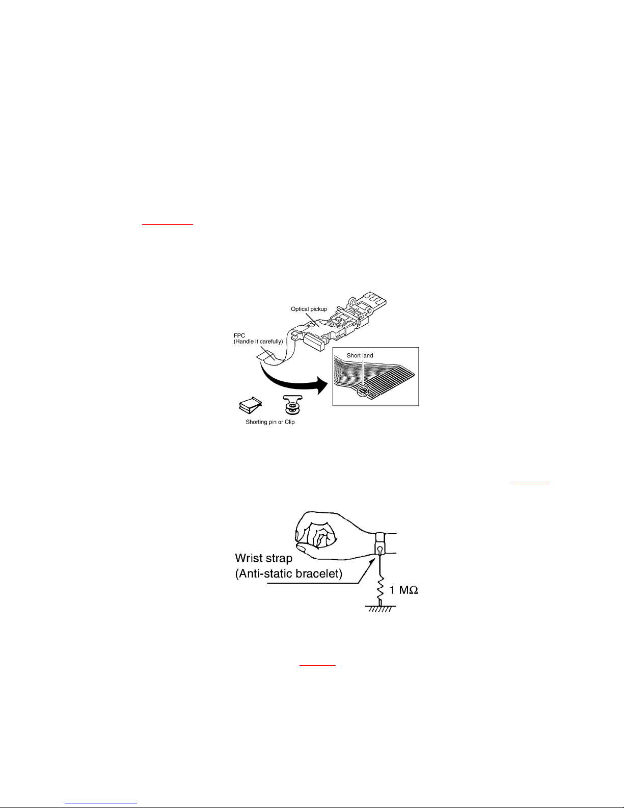
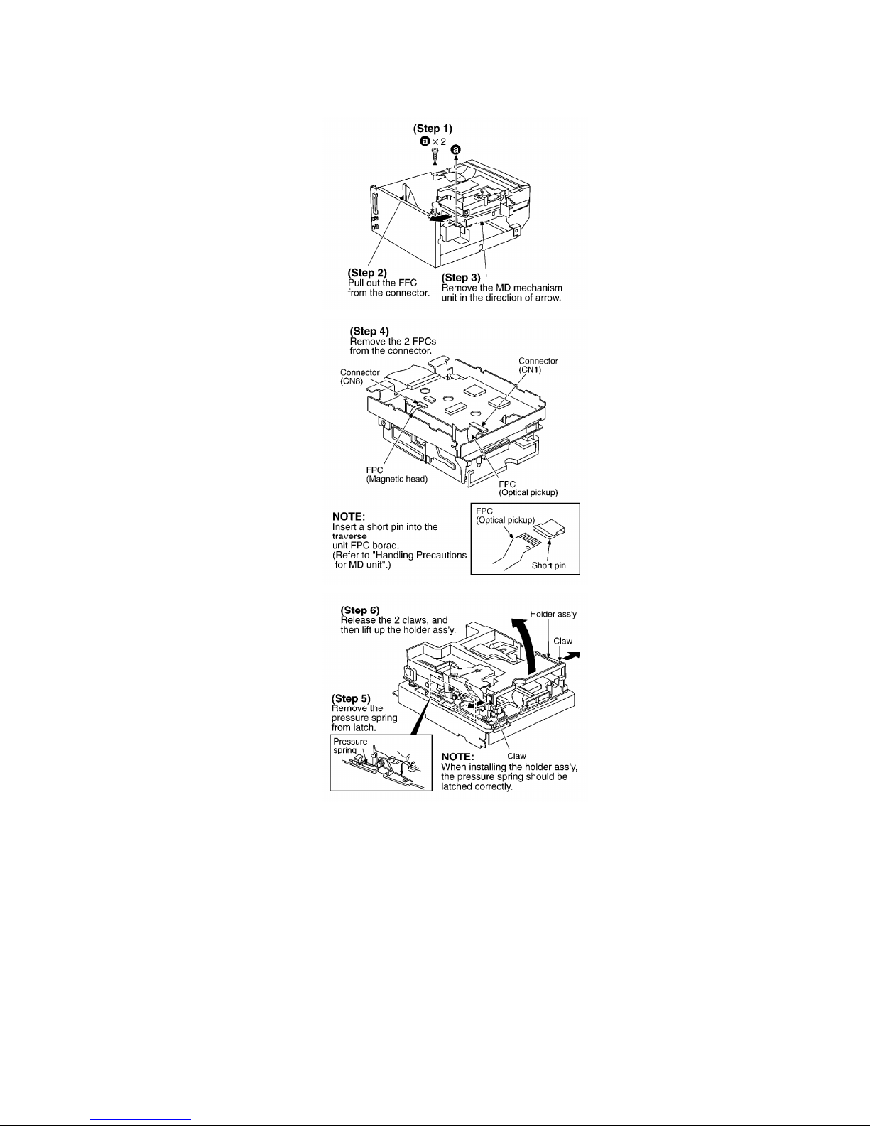
4. Handling Precautions for MD Unit
The laser diode in the MD unit (optical pickup) maybreak down due to potential difference
2

caused bystatic electricityof clothes or human body. So be careful of electrostatic breakdown
during repair of the MD unit (optical pickup).
4.1. Handling of MD Unit (optical pickup)
1. Do not subject the MD unit (optical pickup) to static electricityas
it is extremelysensitive to electrical shock.
2. To protect the breakdown of the laser diode, an anti-static
shorting pin is inserted into the flexible board (FPC board). Refer
to Fig. 4-1.
3. Take care not to applyexcessive stress to the flexible board (FPC
board).
Fig. 4-1.
4.2. Grounding for electrostatic breakdown prevention
4.2.1. Human bodygrounding
Use the anti-static wrist strap to discharge the static electricityfrom your body. Refer to Fig. 4-2.
Fig. 4-2.
4.2.2. Work table grounding
Put a conductive material (sheet) or steel sheet on the area where the MD unit (optical pickup)
is placed, and ground the sheet. Refer to Fig. 4-3.
Fig. 4-3.
3

Caution:
The static electricityof your clothes will not be grounded through
the wrist strap.
So take care not to let your clothes touch the MD unit (optical
pickup).
5. Precaution of Laser Diode
6. Location of Controls
7. Operation Checks and Component Replacement /
Procedures
- This section describes procedures for checking the operation of
the major printed circuit boards and replacing the main
4

components.
- For reassemblyafter operation checks or replacement, reverse the
respective procedures. Special reassemblyprocedures are
described onlywhen required.
7.1. Checking for the main P.C.B.
- Check the main P.C.B. as shown below.
7.2. Checking for the MD servo P.C.B.
7.2.1. Checking for the MD servo P.C.B. (Aside)
- Followthe (Step 1) - (Step 3) of item 7.1.
5

- Check the MD servo P.C.B. (Aside) as shown below.
7.2.2. Checking for the MD servo P.C.B. (B side)
6

7.3. Replacement for the magnetic head and optical pickup
- Followthe (Step 1) - (Step 3) of item 7.1.
7

8

9

10

7.4. Replacement for the belt and loading motor ass’y
- Followthe (Step 1) - (Step 3) of item 7.1.
11

12

7.5. Replacement for the traverse motor ass’y
- Followthe (Step 1) - (Step 3) of item 7.1.
- Followthe (Step 1) - (Step 11) of item 7.3.
13

14

8. Self-Diagnostic Function
This unit is equipped with a Self-Diagnostic Function, so that if the unit operates incorrectly,
the fault is displayed using an error code on the FL displayof the Tuner (ST-HD515MD). The
system control IC and FL displayare part of the tuner so make sure the system has been
connected properlybefore using this function. (This unit can be operated independently,
although the Self-Diagnostic Function cannot be used.) Use this Self-Diagnostic Function when
servicing the unit.
8.1. Setting to the Self-Diagnostic Function
1. Turn on the power.
2. Hold down the button for at least 2 seconds and then
press the button for at least 2
seconds while continuing to hold down the button. Refer
to Fig. 8-1.
The unit sets to Self-Diagnostic Function. Then an error code is
displayed on the FL displayof the Tuner (ST-HD515MD) if any. For
details of the error code, refer to Table 8-1. In case of no error, “
” is displayed on the FL displayof the tuner.
3. If more than one error exists, the displaywill sequentiallyshow
15

the respective error codes each time
button is pressed.
Fig. 8-1.
Table 8-1.
Error code Symptom Possible cause
F15 Interval till MD starts playing is
too long.
-Traverse det. switch (S8) is defective; Check and replace if
necessary.
F28 MD cannot be loaded. -Confirm that the disc is not catching on anything.
-The connection (flexible circuit board or connector cable) between
the
and MD servo circuit board is disconnected or damaged; check and
replace
necessary.
-The MD unit maybe malfunctioning; replace it.
F29 MD cannot be ejected. -Confirm that the disc is not catching on anything.
-The connection (flexible circuit board or connector cable) between
the
and MD servo circuit board is disconnected or damaged; check and
replace
necessary.
-The MD unit maybe malfunctioning; replace it.
8.2. Canceling the Self-Diagnostic Function
The Self-Diagnostic Function can be canceled bypressing the power button (POWER) on the
Amplifier (SE-HD515MD) to turn off the system. And then pressing the power button again to
turn it on again.
8.3. Clearing the Self-Diagnostic Function
The contents of abnormalitydisplayare stored in memory. In order to clear the memory,
continue to press the STOP button for at least 2 seconds while in the Self-Diagnostic Function.
The memorywill clear. Always be sure to clear this memoryafter completing repair.
9. To SupplyPower Source and Signal Check
Caution:
- It is verydangerous to look at or touch the laser beam. (Laser
radiation is invisible.) With the unit turned ON, laser radiation is
16

emitted from the pickup lens.
- Avoid exposure to the laser beam, especiallywhen performing
adjustments.
This unit (SJ-HD515) is designed to operate on power supplied
from the Amplifier (SE-HD515MD) through the Tuner (ST-
HD515MD). When connecting the unit to other system components,
do not connect to the Amplifier (SE-HD515MD) directly. When
operating the unit (SJ-HD515) alone for testing and servicing
without having power supplied from the Amplifier (SE-HD515MD),
use the following method.
9.1. Power Supplyto This Unit alone
1. Setting of the unit switches: Set MARKING to AUTO and TRACK
to ONE. Refer to Fig. 9-1.
2. Short the IC10-pin 67 (TP77) and GND (TP74) with the lead wire.
Refer to Fig. 9-2. (This enables the unit to enter the operation
mode and to active the operation switches on the front panel.)
3. ApplyDC 10 V between the CP304-pin 5 (+10 V) and CP304-pin 11
(GND). Refer to Fig. 9-3. (The LED of REC and PLAY will light up.
The PLAY LED is orange color.)
Fig. 9-1.
Fig. 9-2.
17

Fig. 9-3.
9.2. Preparation for Play/Rec Signal Check
Connect the oscilloscope or the speaker with built-in amplifier to the section between CP304-
pin 12 (R ch OUT) and CP304-pin 17 (A.GND) as well as the section between CP304-pin 14 (L ch
OUT) and CP304-pin 17 (A.GND) and check if the signals are outputting from this unit. Refer to
Fig. 9-3.
9.3. Checking Play/Rec Signal to This Unit alone
9.3.1. NecessaryInstruments
- Recorded MD
- Recordable MD
- Optical fiber cable
- Portable CD player and CD
(You can check this operation with anyother player that has an
optical digital output terminal but the portable CD player. The
following procedure explains check operation with the portable
CD player, but the procedure is the same for other players.)
9.3.2. Playback Signal Check
1. Set the unit so that Power Supplyto This Unit alone as previously
explained.
18

2. Prepare for Play/Rec Signal Check.
3. Set the recorded MD in the unit.
4. Press the button and check if the MD playbacks
normally. (When the button is pressed, the PLAY LED
turns green.) Refer to Fig. 9-4.
5. Remove the MD after check. (Continued to Recording Signal
Check.)
Fig. 9-4.
9.3.3. Recording Signal Check
1. After completing the item 5 of Playback Signal Check, connect to
the portable CD player (or anyother player with an optical digital
output terminal). Refer to Fig. 9-5.
2. Set the recordable MD.
3. Press the REC button. The REC LED (red color) blinks. Refer to
Fig. 9-4.
4. Playback the CD and press the button. The recording
starts. Refer to Fig. 9-4.
5. Press the button. (UTOC will be written.) Refer to Fig. 9-4.
6. Playback the MD and check if the MD is recorded.
7. Remove the MD after check.
19

8. Turn off the power, and remove the lead wire between the IC10-
pin 67 (TP77) and GND (TP74). (Refer to Power Supply to This Unit
alone.)
Fig. 9-5.
10. Schematic Diagram Notes
- This schematic diagram maybe modified at anytime with the
development of newtechnology.
Notes:
S1:
PROTECTdet. switch
S2:
REFLECTdet. switch
S3:
LOAD OPEN det. switch
S4:
DISC IN det. switch
S5:
LOAD PLAY/REC det. switch
S6:
LOAD PLAY det. switch
S7:
LOAD TRG det. switch
S8:
20
Table of contents
Other Panasonic Mini Disc Player manuals

Panasonic
Panasonic Lx-600 User manual

Panasonic
Panasonic SJ-MJ55GH User manual

Panasonic
Panasonic SJ-MJ55GH User manual

Panasonic
Panasonic SJ-MJ70 User manual

Panasonic
Panasonic SJ-MJ95 User manual

Panasonic
Panasonic SJ-MR220 Administrator Guide

Panasonic
Panasonic SJ-MJ75 User manual

Panasonic
Panasonic SJ-MJ17 User manual

Panasonic
Panasonic SJ-MJ50GH User manual

Panasonic
Panasonic SJ-MD150 Building instructions