Panasonic SJ-MJ55GH User manual

ORDER No.AD0211153C3
Portable MD Player
SJ-MJ55GH
Colour
(S)...................Silver Type
SPECIFICATIONS
Specifications

Audio
System:MiniDisc digital audio system
Beam source:Semiconductor laser
Wave length:780 nm
Sampling frequency:44.1 kHz
Coding:Adaptive Transform Acoustic
Coding (ATRAC/ ATRAC3)
No. of channels:2 (left and right, stereo)
1 (monaural)
Frequencyresponse:20 Hz~20 kHz (+0 dB, -6dB)
Wowand flutter:Belowmeasurable limit
General
Headphones:
Output level (approx.):3.0 mW+3.0 mW
Inpedance (approx.):32
Speakers (ceramic card type):
Output level (approx.):45 mW+45 mW
Inpedance (approx.):200 / 1kHz
Power supply
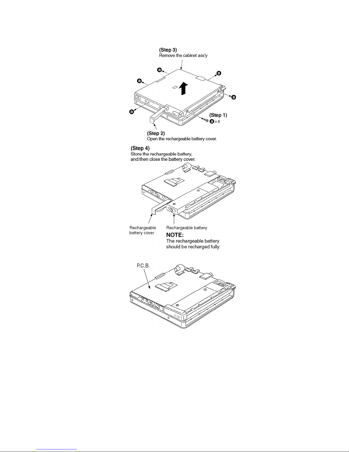
Rechargeable battery:DC 1.2V
(included rechargeable battery)
Battery:DC 1.5V (One LR6, AA, UM-3 battery)
Dimensions (WxHxD)
Cabinet dimensions:79.9x72.7x14.1 mm
incl.projecting parts:80.9x74.2x17.0 mm
Weights:96 g (with battery)
69 g (without battery)
Playtime
[Approximate operating time in hours (in hold mode, at 25°C, on
a flat, stable surface)]
Batterytype:Playtime (Stereo/ LP2/ LP4)
Rechargeable:40 hours/ 53 hours/ 70 hours
Panasonic alkaline:63 hours/ 93 hours/ 121 hours
Both together:103 hours/ 148 hours/ 193 hours
[When the rechargeable battery(included) is fullyrecharged.]
AC adaptor and charger
AC adaptor input:AC220 V, 50/60 Hz, 5 VA
AC adaptor output and
Charger input:
DC 3.5 V, 0.5A
Charger output:DC 2V, 0.5 A
Recharging time:About 3.5 hours

Notes:
- The playtime maybe less depending on the operating
conditions.
- Specifications are subject to change without notice. Weight
and dimensions are approximate.
2002 Matsushita Electric Industrial Co., Ltd. All rights reserved.
Unauthorized copying and distribution is a violation of law.
1. Accessories
- Stereo earphones...................................................1 pc. /
(L0BAB0000174)
- Wired remote control..............................................1 pc. /
(N2QCBD000020)
- External batterycase..............................................1 pc. /
(K3ZZ00200038)
- Nickel-metal hydride rechargeable battery.............1 pc. /
(RFKFFAZ01EM1)
- Soft case.................................................................1 pc. / (RFC0074-H)
- Speaker/Batterycharger............................................1 pc. /
(L0EAAB000011)
- AC adaptor...............................................................1 pc. /
(N0JCBD000001)
2. Precaution of Laser Diode

3. Operating Instructions
4. Handling Precautions for MD Mechanism (Optical
pickup)
The laser diode in the MD mechanism (optical pickup) maybreak down due to potential
difference caused bystatic electricityof clothes or human body.
So, be careful of electrostatic breakdown during repair of the traverse deck (optical pickup).
4.1. Handling the MD mechanism (optical pickup)
1. The MD mechanism (optical pickup) is an extremelyhigh-
precision construction and must not be subjected to impact,
excessive vibration, or other types of rough handling.
2. In order to prevent static electricitydamage to the laser diode,
use a short pin or similar tool to short the optical pickup’s flexible
circuit boards after theyhave been disconnected from the main
circuit board. (as shown in Fig. 1 )
3. Handle the flexible circuit boards with care; excessive force could
cause them to be broken.
4. Do not turn the pre-set variable resistor (for adjustment of the
laser power); it has been adjusted at the factory.
(as shown in Fig. 2 )
Fig. 1

Fig. 2
4.2. Grounding for electrostatic breakdown prevention
1. Human bodygrounding
Use the anti-static wrist strap to discharge the static electricity
from your body. (as shown in Fig. 3 )
2. Work table grounding
Put a conductive material (sheet) or steel sheet on the area where
the traverse deck (optical pickup) is placed, and ground the sheet.
(as shown in Fig. 4 )
Caution
The static electricityof your clothes will not be grounded through
the wrist strap.
So, take care not to let your clothes touch the traverse deck (optical
pickup).
Fig. 3

Fig. 4
5. Operation Checks and Component Replacement
Procedures
- This section describes procedures for checking the operation of
the major printed circuit boards and replacing the main
components.
- For reassemblyafter operation checks or replacement, reverse the
respective procedures. Special reassemblyprocedures are
described onlywhen required.
- After replacing the main components (optical pickup or traverse
motor, etc.) of mechanism unit block, change to the adjust mode,
and then perform the adjustments (Laser power, off-set, ROM/
RAM).
5.1. Checking for the P.C.B.

- Check the P.C.B. as shown below.

5.2. Replacement for the intermediate cabinet
- Followthe (Step1)-(Step3) of item 5.1.

5.3. Replacement for the disk cover ass’yand the link units (L), (R)
- Followthe (Step1)-(Step3) of item 5.1.
- Followthe (Step1)-(Step4) of item 5.2.

5.4. Replacement for the traverse motor
- Followthe (Step1)-(Step3) of item 5.1.

5.5. Replacement for the optical pickup
- Followthe (Step1)-(Step3) of item 5.1.
- Followthe (Step1)-(Step5) of item 5.4.


6. Measurements and Adjustments
Note:
After replacing the main components (optical pickup, traverse motor, IC201, IC202 or P.C.B.
ass’y, etc.) of mechanism unit block, change to the adjust mode, and then perform the “Laser
power adjustment”, “Off-setautomatic adjustment” and “Playback-onlydisc/magneto-optical
disc automatic adjustment”.
6.1. Instruments to prepare
1. Playback-onlydisc (Test disc RFKV0006)
2. Commerciallyavailable recordable disc (fullyrecorded with
music) (magneto-optical disc)
3. Laser power meter (LE8010 or compatible meter)
4. Remote controller (Parts No: N2QCBD000020) [or Remote
controller of SJ-MJ88 etc. (Parts No: RFEV025P-SM)]
6.2. Laser power adjustment, Off-set automatic adjustment, Playback
-onlydisc/magneto-optical disc automatic adjustment magnet
6.2.1. Enter the adjustment mode
Note:
For use of MD cartridge type laser power meter, disassemble this unit into the state of onlythe
mechanism unit before perform the laser power adjustment (as for the method of disassembly,
refer to “5.2. Replacement for the intermediatecabinet”).

1. Set the batteryand connect the remote controller. (The position of
the HOLD switch of remote controller is “OFF”.)
2. Turn off the power, and switch main unit’s HOLD switch off.
3. Press the VOL+( ), VOL-( ), ( ), and ( )keys on the
remote controller within two seconds. (asshown in Fig. 5 )
Fig. 5
4. When the adjustment mode is activated, “T0E ” will be displayed
on the LCD of remote controller. After “T0E ” is displayed, select
the desired adjustment item with the button or button of
the remote controller. (If it is not displayed, perform the
procedures written above again.)
*In the displayof T0E ~ TFE shown above, you must adjust T0E , T1E , T2E and T3E . You must
perform the adjustment byobserving the order T0E T1E T2E T3E .
Note:
If it is going to perform “T2E” and “T3E”, without performing “T1E”, it will be displayed as “NG”.
If it is going to perform “T3E” when “T2E” is “NG”, it will be displayed as “NG”.

6.2.2. Laser Power Adjustment
Adjust each laser power: read power for reading (play).
6.2.2.1. Set the Unit to the Adjustment Mode
Cautions
About handling the optical pickup and the magnetic head.
- The optical pickup is structured precisely; therefore, it is very
fragile. Be careful not to touch it with the edge of the laser power
meter. Do not touch the lens.
- The sensor of the laser power meter is a veryfine part. Be careful
not to touch it to the optical pickup lens.
- The focus point of the laser reaches to 356°F. Therefore, avoid
adjusting using laser power for a long time because the sensor of
the laser power meter maybe burned.
- Do not set the unit to the laser power adjustment mode with the
MD loaded. Doing so mayresult in damage to the MD.
- Laser diode in the optical pickup maybe destroyed bythe static
electricitygenerated in your clothes or body. Be especiallycareful
with the static electricity.
6.2.2.2. Adjustment Procedure
1. Have “T0**” indicated on display, and move the optical pickup to
the most inside (onlywhen a MD cartridge type laser power meter
is used).
2. Set the laser power meter.
[For use of stick type laser power meter.]
2-1 Uncover the laser power meter (as shown in Fig. 6 ).
2-2 Locate the sensor of the laser power meter right over above
the optical pickup (horizontallyat a level of the disc position).
(as shown in Fig. 7 )
[For use of MD cartridge type laser power meter.]
2-1 Open the shutter of the laser power meter. (as shown in Fig. 9 )
2-2 Set the laser power meter. (as shown in Fig. 8 )
Fig. 6

3. Press the keyof the remote controller (“T0E ” changes to
“LD ” of the LCD).
4. Press the keyof the remote controller (“LD ” changes to “LP ”
of the LCD).
5. Set the laser power at 600 W±10%byusing VOL+ and VOL- key
of the remote controller. / [Specified range: 600 W±10%]
Caution:
Proceeding on to the subsequent adjustment procedure with the
read power exceeding “over 660 W” will result in damage to the
optical pickup.
6. Set the laser power with the keyof the remote controller (“LP
” changes to “LDOK ” in the LCD).
7. Press the keyof the remote controller (“LDOK ” changes to
“T0E ” on the LDC.
8. Remove the laser power meter. Laser power adjustment is
finished.
<Stick type>
Fig. 7

<MD cartridge type>
Fig. 8
[Howto open the shutter]
1. Insert a thin and hard card to the crevice between laser power
meter, and pull a card in the direction of an arrow(1).
2. Astopper moves in the direction of an arrow(2).
3. Move the shutter in the direction of an arrow(3) and the shutter
opens.
Caution:
Please be sure to shut the shutter after the adjustment end.
Fig. 9

6.2.3. Off-set automatic adjustment
1. With “T1E ” displayed, leave the disc cover open.
2. Pressing the keyon the remote controller will start
adjustment.
3. During adjustment, “FADJ ” is displayed on the LCD of the remote
controller. If there is no abnormality, “FOK ” will be displayed.
4. Pressing the keywhile “FOK ” is displayed will return to the
“T1E ” displaymode.
6.2.4. Magneto-optical disc automaticallyadjustment
1. Have “T2E ” indicated on display, and set the full-recorded
magneto-optical disc. (Check to make sure the disc is properly
seated.)
2. Press keyof the remote controller. The adjustment is
started.
3. During adjustment, “AADJ ” is displayed on the LCD of the

remote controller. / If there is no abnormality, “AOK ” will be
displayed.
Note:
If it is displayed “ANG ”, check “7. Troubleshooting Guide” in the order.
4. Press key(“AOK ” or “ANG ” changes to “T2E ”).
5. After the adjustment is finished, remove the disc.
6.2.5. Playback-onlydisc automatic adjustment
1. Have “T3E ” indicated on display, set the playback-onlydisc. /
(Check to make sure the disc is properlyseated.)
2. Press keyof the remote controller. The adjustment is
started.
3. During adjustment. “AADJ ” is displayed on the LCD of the
remote controller. / If there is no abnormality, “AOK ” will be
displayed.
Note:
If it is displayed “ONG ”, check “7. Troubleshooting Guide” in the order.
4. Press key(“OOK ” or “ONG ” changes to “T3E ”).
5. After the adjustment is finished, remove the disc.
6.2.6. Howto get out the adjustment mode
Remove the batterywhen you finish the adjustment.
6.3. Checking the main unit's keys
1. Set the batteryand connect the remote controller.
2. Turn off the power, and switch main unit’s HOLD switch ON.
3. Press the VOL+( ), VOL-( ), ( ), and ( ) keys on the
remote controller within two seconds. (asshown in Fig. 5 )
4. When the unit enters the unit keycheck mode, the displayshows
“E KEX ”. While “E KEX ” is displayed, press the , , ,
VOL+, VOL- and HOLD keys of the unit. / *When the first keyis
pressed, the displaywill change to “E ”.

Main unit’s keys LCD displayposition and letters
After the second keyis pressed, the first digit displayed
will change from “ ” to “O ”.
HOLD OFF
VOL+ After the second keyis pressed, the second digit
displayed will change from “ ” to “O ”.
VOL-
After the second keyis pressed, the third digit displayed
will change from “ ” to “O ”.
5. After all keys have been pressed and there is no abnormality, “E
OOO ” will be displayed.
6. Perform belowvoltage check about the keys come under if it is
not displayed “E OOO ”.
Main unit’s keys Check points ON OFF
IC201 48pin 0V 2.2V
HOLD TP428 0V 2.2V
VOL+ TP421 0V 2.2V
VOL- TP421 0.58V 2.2V
TP421 1.13V 2.2V
TP421 1.69V 2.2V
Note:
Refer to “12. Printed Circuit Board Diagram” for the test points.
7. Remove the batterywhen you exit from this mode.
7. Troubleshooting Guide
Other manuals for SJ-MJ55GH
1
Table of contents
Other Panasonic Mini Disc Player manuals

Panasonic
Panasonic SJ-MJ10 User manual

Panasonic
Panasonic SJ-HD515 User manual

Panasonic
Panasonic SJ-MR240 User manual

Panasonic
Panasonic SJ-MJ50GH User manual

Panasonic
Panasonic SJ-MJ88 User manual

Panasonic
Panasonic Lx-600 User manual

Panasonic
Panasonic SJ-MJ95 User manual

Panasonic
Panasonic SJ-MR220 Administrator Guide

Panasonic
Panasonic SJ-MJ55GH User manual

Panasonic
Panasonic SJ-MD150 Building instructions