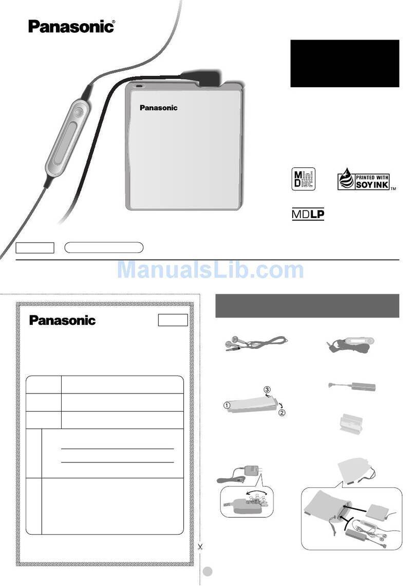
Panasonic SJ-MJ70 User manual

ORDERNo.AD9903073C2
PortableMDPlayer
SJ-MJ70
Colour
(S)...................Silver Type
Areas
EB...................Great Britain.
EG...................Germanyand Italy, etc.
SPECIFICATIONS
Specifications
1

Mechanism unit:RAE1610ZMechanism Series
Audio
System: MiniDisc digital audiosystem
Laser: Semiconductorlaser (=790 nm)
Sampling frequency: 44.1kHz
Coding: AdaptiveTransform Acoustic
Coding (ATRAC)
No. of channels: 2(left and right, stereo)
1(monaural)
Frequencyresponse: 20 Hz-20 kHz (+0dB, -6dB)
Wowand flutter: Belowmeasurablelimit
General
Output Jack: Phones, 14
Power output: 6mW+6mW
Power supply
Rechargeablebattery: DC 1.2V
(includedrechargeablebattery)
Battery: DC 1.5V (OneLR6, AA, UM-3battery)
Dimensions(WxHxD)
Cabinet dimensions: 71.7x79.7x14.5mm
incl.projecting parts: 73.3x81.3x15.3mm
Weight: 94 g(withbattery)
69 g(without battery)
Playtime
(Whenusedinholdmode, at 25°C, on aflat, stablesurface)
Batterytype: Playtime
Rechargeable: About 7hours
Panasonicalkaline: About 24 hours
Bothtogether: About 32 hours
Charger
Input: AC 120-240 V (forContinental
Europe)/ AC230-240 V (forUK), 50 Hz
4W
Output: DC 340 mA(forContinental Europe)/
DC 350 mA(forUK), 1.2V
Notes:
- Theplaytime maybeless depending on theoperating
conditions.
- Specificationsare subject tochargewithout notice. Weight
and dimensionsare approximate.
1999 Matsushita ElectricIndustrial Co., Ltd. / / All rights
reserved. Unauthorized copying and / / distribution isaviolation
of law.
2
1. Precaution of Laser Diode
2. Operating Instructions
3. Handling Precautions for Traverse Deck
(Mechanism Unit)
The laserdiode inthe mechanismunit (optical pickup) maybreak downdue topotential
difference causedbystatic electricityof clothes orhumanbody.So, be careful of electrostatic
breakdownduring repairof the mechanismunit (optical pickup).
3.1. Mechainsm Unit(optical pickup)
1. Donot subject the mechanism unit(optical pickup) to static
electricityas itisextremelysensitive to electrical shock.
2. The short land between the No. 11 (GND)and No. 12 (LD)pins on
the flexibleboard isshorted with asolder build-up to prevent
damage to the laser diode. (Asshownin Fig. 1.)
To connect to the PCboard, be sure to open byremoving the
solder build-up, and finish the work quickly.
3. Take care not to applyexcessive stress to the flexibleboard (FFC).
4. Donot turn the variableresistor (laser power adjustment). Ithas
alreadybeen adjusted.
Fig. 1
3

3.2. Grounding for electrostaticbreakdownprevention
1. Human bodygrounding
Use the anti-staticwrist strap to discharge the staticelectricity
from your body. (Asshownin Fig. 2.)
2. Work tablegrounding
Put aconductive material (sheet) or steel sheet on the area where
the optical pickup isplaced, and ground the sheet.
Caution:
The staticelectricityof your clothes will not be grounded through
the wrist strap. So, take care not to let your clothes touch the
traverse deck (optical pickup). Fig. 2
4. Operation Checks and Main Component
Replacement Procedures
4

5

6

7

5. Measurements and Adjsutments
Note:
If you exchange mechanismunit “RAE1610Z” whenyou repair, you must perform the automatic
adjustment and checking of “playback-onlydisc” “magneto-optical disk” at the “adjsutment
mode”.
Discs toprepare
1. Test disc (Playback-onlydisc)
8

2. Commerciallyavailablerecordabledisc (fullyrecorded with
music) (magneto-optical disc)
Playback-onlydisc/magneto-optical disc automatic adjustment
-Preparations for adjustment
1. Check the PCboard. (Refer to the item of “Checking for the
P.C.B.”in“Operation Checks and MainComponent Replacement
Procedures”).
2. Check the laser emission.
A. Make the player to the mechanism unitonly. (Refer to Fig.3or
the item of “Replacement for the intermediate cabinet” in
“Operation Checks and MainComponent Replacement
Procedures).
B. Set the battery.
C. Whilepressing the batterycover to connect the batterypower,
continuouslypress the OPEN/CLOSE switch. (Asshownin Fig.3
)
D. The optical pickup moves up and downand emits alaser.
(Caution: Donot look directlyat the laser light source.)Ifthe
laser does not emitabeam, follow the item of “operation
check” in“Troubleshooting Guide ”and check for a
malfunction. Fig.3
3. Mount the mechanism uniton the disc cover. (Showninthe item
of “Replacement for the intermediate cabinet” in“Operation
Checks and MainComponent Replacement Procedures”).
4. Connect the remote controller.
5. Check that the batteries are loaded, and set the test disc (TOC
read).
9

6. Turn off the power. Then, with the mainunit’sHOLDswitch at
OFF, press the VOL+, VOL-, , and buttons on the
remote controller withintwoseconds without pressing the OFF
button.
A. Using your thumb, whilepressing the VOL+ button, also press
the VOL- button.
B. Then, whilestill pressing the VOL- button, release your thumb
from the VOL+ and press the button.
C. Whilestill pressing the button, release your thumb from
the VOL- button and press the button. Then, whilestill
pressing the button, release your thumb from the
button and then from the button. (a-c are shownin Fig.4
)Fig.4
10

7. When the adjustment mode isactivated, “TA”will be displayed.
After “TA”isdisplayed, select the desired adjustment item with
11

the button or button.
Adjustment mode
Adjustment mode Display
Playback-onlydisc automatic
adjustment T1
Magneto-optical disc automatic
adjustment T2
Playback-onlydisc automatic
adjustment value check T3
Magneto-optical disc automatic
adjustment value check T4
Laserpowercheck T5
EFM jittermeasurement T6
ADIP jittermeasurement T7
Errorrate measurement T8
Tilt measurement T9
PWB inspection (audiotest) TA
*Inthe displayof T1 ~ TA shownabove, you must adjust T1 and T2.
-Playback-onlydisc automaticadjustment / With the T1 displayed,
press the PLAYkeyto active the adjustment mode. / During the
adjustment, “OADJ” will be displayed. Ifthere are no
abnormalities, “OOK”will be displayed. (Note1) / Ifthe
keyispressed whilethe “OOK”or “ONG”isbeing displayed, the
setting returns to the T1 display. / When finished, remove the disc.
/
Note 1:
When“ONG” is displayed, followthe itemof “operation check” in“Troubleshooting Guide” and
check fora malfunction.
-Magneto-optical disc automaticadjustment / With the T2 displayed,
set the commerciallyavailablerecordabledisc (which isfully
recorded with music). / Press keyto activate the
adjustment mode. / During the adjsutment, “AADJ” will be
displayed. Ifthere are no abnormalities, “AOK”will be displayed.
(Note 2) / If keyispressed whilethe “OOK”or “ONG”is
being displayed, the setting returns to the T2 display.
Whenfinished, remove the disc.
12

Note 2:
When“ANG” is displayed, followthe itemof “operation check” in“Troubleshooting Guide” and
check fora malfunction.
*To exit the adjustment mode, remove the battery.
Checking the mainunit's keys
1. Check the PCboard. (Refer to the item of “Check for the P.C.B.”
in“Operation Checks and MainComponent Replacement
Procedures”).
2. Set the batteryand connect the remote controller.
3. Turn off the power. Then, with the mainunit’sHOLDswitch at
OFF, press the VOL+, VOL-, , and buttons on the
remote controller withintwoseconds without pressing the OFF
button.
A. Using your thumb, whilepressing the VOL+ button, also press
the VOL- button.
B. Then, whilestill pressing the VOL- button, release your thumb
from the VOL+ and press the button.
C. Whilestill pressing the button, release your thumb from
the VOL- button and press the button. Then, whilestill
pressing the button, release your thumb from the
button and then from the button. (a-c are shownin Fig.5
)Fig.5
13

4. When entering the mainunit’skeycheck mode, “KEY” will be
displayed.
14

With “KEY” displayed, press , , , VOL(+/-)
keysand set the HOLDswitch to OFF (no order). Then, “KEY OK”
will be displayed.
Note:
If “KEY OK” is not displayed, check the following voltage foreachkey.
Key Test point ON OFF
IC201-35 pin 0V 2.4V
HOLD TPX110 2.4V 0V
VOL+ TP307 0V 2.4V
VOL- TP307 0.6V 2.4V
TP307 1.2V 2.4V
TP307 1.8V 2.4V
To exit the mainunit’s keycheck mode, remove the battery.
Note:
Referto“PrintedCircuit Boardand Wiring Connection Diagram” forthe test points.
6. Troubleshooting Guide
15

16

17

18

19

20
Table of contents
Other Panasonic Mini Disc Player manuals

Panasonic
Panasonic SJ-MR240 User manual

Panasonic
Panasonic SJ-MJ17 User manual

Panasonic
Panasonic SJ-MJ75 User manual

Panasonic
Panasonic SJ-MJ75 User manual

Panasonic
Panasonic SJ-MD150 Building instructions

Panasonic
Panasonic SJ-MJ55GH User manual

Panasonic
Panasonic SJ-MJ97 User manual

Panasonic
Panasonic SJ-HD515 User manual

Panasonic
Panasonic SJ-MJ10 User manual

Panasonic
Panasonic SJ-MJ95 User manual