Samson MPL 1640 User manual


Introduction 1
MPL 1640 Features 1
Guided Tour 3
Overview 3
Channel 4
Main Section 6
Rear Panel 8
Connecting the MPL 1640 10
Balanced connectors 10
Unbalanced connectors 10
Mic connectors 10
Insert connectors 11
Setting Up and Using the MPL 1640 12
Setting the correct gain structure 12
Grounding Techniques 15
Using Bus 3/4 17
Using Pan 18
Using Equalization 19
Using the Auxiliary Sends and Returns 20
Using Channel Inserts 21
Using PFL Solo 22
Changing the MPL 1640 from Rack-mount to
Tabletop 23
Applications 24
Using the MPL 1640 as a main live mixer 24
Using the MPL 1640 as an onstage monitor mixer 25
Using the MPL 1640 as a keyboard submixer 26
Using the MPL 1640 as a recording mixer 27
Appendix A: Changing the MPL 1640 Voltage 28
Appendix B: Block Diagram 29
Specifications 30

Introduction
Congratulations on purchasing the Samson MPL 1640 mixer! In this manual,
we’ll take you on a guided tour through all the features of this powerful and flexi-
ble device, and we’ll tell you how to get the most out of the MPL 1640 in your
particular environment. If this is your first mixer, we’re confident that you’ll find
the information in these pages valuable—read them carefully before proceeding
further. If, on the other hand, you’ve had some previous experience with mixers
and dislike reading manuals—well, we have to admit that the 1640 was
designed so you folks can start using it right away—but we still suggest you first
take some time to go through these pages so you can fully understand how
we’ve implemented a number of unique features.
We’ll start with system features and an overview of the MPL 1640, followed by a
guided tour of its front and rear panels. Then we’ll describe how the MPL 1640
should be connected to your existing equipment (including wiring diagrams) and
talk about the important topics of signal flow, gain structure, and grounding
techniques. Next, we’ll cover a number of specific MPL 1640 features (such as
busing, panning, equalization, auxiliary sends and returns, channel inserts, and
soloing) in detail. Finally, we’ll wrap things up with a series of applications notes
describing how you can use the MPL 1640 for both live performance and
recording.
Oh, and one last thing—don’t forget to fill out and mail in the enclosed warranty
card! This will enable you to receive online technical support and will allow us to
send you updated information about this and other Samson products in the
future.
SPECIAL NOTE: Should your unit ever require servicing, a Return Authorization
number (RA) is necessary. Without this number, the unit will not be accepted.
Please call Samson at (516) 932-1062 for a Return Authorization number prior
to shipping your unit. Please retain the original packing materials and, if
possible, return the unit in its original carton and packing materials.
MPL 1640 Features
“MPL” stands for “Microphone/Program/Line” and the name describes the broad
range of signals which can be handled by this powerful console. In fact, the
compact design of the MPL 1640 belies an extraordinary versatility. Add excel-
lent sound quality to the equation, and you’ve got a product which is equally
useful as a live performance mixer, a keyboard submixer, or even a main
recording mixer (you’ll find descriptions of each of these applications at the
conclusion of this manual). Here are some of the MPL 1640’s main features:
• 16 input channels, each providing electronically balanced inputs that can be
used for a broad range of microphone or line-level input sources.
• An electronically balanced main stereo output for connection to a power
amplifier or tape recorder, as well as a secondary Bus 3/4 output for connec-
tion to auxiliary equipment such as a monitoring system.
1

Introduction
• 3 auxiliary sends and 3 stereo auxiliary returns (which can be used as 6
monophonic returns). Auxiliary return balance controls allow you to adjust
the relative levels of the left and right inputs for each return. Aux send 1 is
pre-fader and pre-equalizer, making it ideal for use as a headphone or moni-
tor cue mix, while Aux sends 2 and 3 are post-fader and post-equalizer.
• Independent 3-band equalization for each channel, with 15 dB of cut or boost
for low (80 Hz) and high (10 kHz) frequencies and 12 dB of cut or boost for
the mid (800 Hz) frequency.
• Constant level pan controls for placing each channel in the left-right stereo
spectrum.
• Channel PFL (Pre-Fade Listen) switches enable channels to be selectively
soloed.
• Bus switches on each channel allow signal to be muted or routed to a
separate stereo Bus 3/4 output.
• Channel input trim controls are continuously adjustable from +4 to -50 dB,
making it possible to use the MPL 1640 with a wide variety of signal sources
and outboard equipment.
• Center detents for all pan, balance, and EQ controls, making it easy to use
the MPL 1640 even in low-light situations such as live performance.
• Sixteen high-quality short-throw channel faders, along with two independent
Main stereo output faders. Each is detented at its “0” (unity gain) position.
• Peak input LEDs for each channel, showing you when an input signal is
overloading or near overloading (these illuminate 5 dB prior to distortion).
• Channel inserts for twelve of the sixteen channels, enabling you to use out-
board signal processors such as outboard equalizers, compressor/ limiters,
or noise gates in a standard “effect loop.” In addition, Main Mix and Bus 3/4
inserts allow you to process the final output signal in the same way.
• The provision of 48v phantom power makes it possible to plug high-quality
condenser microphones directly into the MPL 1640, without the need for
expensive and cumbersome external power supplies.
• A powerful and flexible front-panel metering system, which includes a seven-
segment meter that allows you to view at a glance the continuous main out-
put level or PFL solo level. Also included are various LEDs which show the
status of various conditions within the MPL 1640.
• An independent front-panel headphone jack with dedicated volume control.
• The MPL 1640 can be mounted in any standard 19” rack (taking 8 rack
spaces), making it easy to integrate into any existing system. When rack-
mounted, its connector panel rotates to the rear for easy accessibility.
• Last but certainly not least, an affordable price. The MPL 1640 has been
designed from the ground up to provide versatility and excellent sound
quality without breaking the bank.
2

Guided Tour - Overview
The following illustration shows an overview of the front panel of the MPL 1640:
3
+4 -50
INPUT TRIM
0
-10
-15 +15
HIGH
0
-12 +12
MID
0
-15 +15
LOW
0
+10
AUX 1
0
−∞
+10
AUX 2
0
−∞
+10
AUX 3
0
−∞
PFL
BUS
ON
OFF
3 / 4
L / R
1
-∞
dB
PEAK
+4 -50
INPUT TRIM
0
-10
-15 +15
HIGH
0
-12 +12
MID
0
-15 +15
LOW
0
+10
AUX 1
0
−∞
+10
AUX 2
0
−∞
+10
AUX 3
0
−∞
R
PAN
L
16
PEAK
+4 -50
INPUT TRIM
0
-10
-15 +15
HIGH
0
-12 +12
MID
0
-15 +15
LOW
0
+10
AUX 1
0
−∞
+10
AUX 2
0
−∞
AUX 3
0
−∞
12
PEAK
+4 -50
INPUT TRIM
0
-10
-15 +15
HIGH
0
-12 +12
MID
0
-15 +15
LOW
0
+10
AUX 1
0
−∞
+10
AUX 2
0
−∞
+10
AUX 3
0
−∞
6
PEAK
+4 -50
INPUT TRIM
0
-10
-15 +15
HIGH
0
-12 +12
MID
0
-15 +15
LOW
0
+10
AUX 1
0
−∞
+10
AUX 2
0
−∞
+10
AUX 3
0
−∞
2
+15
0
PEAK
+4 -50
INPUT TRIM
0
-10
-15 +15
HIGH
0
-12 +12
MID
0
-15 +15
LOW
0
+10
AUX 1
0
−∞
+10
AUX 2
0
−∞
+10
AUX 3
0
−∞
3
PEAK
+4 -50
INPUT TRIM
0
-10
-15 +15
HIGH
0
-12 +12
MID
0
-15 +15
LOW
0
+10
AUX 1
0
−∞
+10
AUX 2
0
−∞
+10
AUX 3
0
−∞
4
PEAK
+4 -50
INPUT TRIM
0
-10
-15 +15
HIGH
0
-12 +12
MID
0
-15 +15
LOW
0
+10
AUX 1
0
−∞
+10
AUX 2
0
−∞
+10
AUX 3
0
−∞
5
PEAK
+4 -50
INPUT TRIM
0
-10
-15 +15
HIGH
0
-12 +12
MID
0
-15 +15
LOW
0
+10
AUX 1
0
−∞
+10
AUX 2
0
−∞
+10
AUX 3
0
−∞
7
PEAK
+4 -50
INPUT TRIM
0
-10
-15 +15
HIGH
0
-12 +12
MID
0
-15 +15
LOW
0
+10
AUX 1
0
−∞
+10
AUX 2
0
−∞
+10
AUX 3
0
−∞
8
PEAK
+4 -50
INPUT TRIM
0
-10
-15 +15
HIGH
0
-12 +12
MID
0
-15 +15
LOW
0
+10
AUX 1
0
−∞
+10
AUX 2
0
−∞
+10
AUX 3
0
−∞
9
PEAK
+4 -50
INPUT TRIM
0
-10
-15 +15
HIGH
0
-12 +12
MID
0
-15 +15
LOW
0
+10
AUX 1
0
−∞
+10
AUX 2
0
−∞
+10
AUX 3
0
−∞
10
PEAK
+4 -50
INPUT TRIM
0
-10
-15 +15
HIGH
0
-12 +12
MID
0
-15 +15
LOW
0
+10
AUX 1
0
−∞
+10
AUX 2
0
−∞
+10
AUX 3
0
−∞
11
PEAK
+10
+4 -50
INPUT TRIM
0
-10
-15 +15
HIGH
0
-12 +12
MID
0
-15 +15
LOW
0
+10
AUX 1
0
−∞
+10
AUX 2
0
−∞
AUX 3
0
−∞
13
PEAK
+10
+4 -50
INPUT TRIM
0
-10
-15 +15
HIGH
0
-12 +12
MID
0
-15 +15
LOW
0
+10
AUX 1
0
−∞
+10
AUX 2
0
−∞
AUX 3
0
−∞
14
PEAK
+10
+4 -50
INPUT TRIM
0
-10
-15 +15
HIGH
0
-12 +12
MID
0
-15 +15
LOW
0
+10
AUX 1
0
−∞
+10
AUX 2
0
−∞
AUX 3
0
−∞
15
PEAK
+10
LR
R
PAN
L
R
PAN
L
R
PAN
L
R
PAN
L
R
PAN
L
R
PAN
L
R
PAN
L
R
PAN
L
R
PAN
L
R
PAN
L
R
PAN
L
R
PAN
L
R
PAN
L
R
PAN
L
R
PAN
L
+20
RETURN 1 LEVEL
0
−∞
+20
0
−∞
RETURN 2 LEVEL
+20
0
−∞
RETURN 3 LEVEL
R
BALANCE
L
R
BALANCE
L
R
BALANCE
L
HEADPHONES
3 - 4
LEVEL
010
−∞ +15
STEREO AUXILIARY RETURNS
12345678910 11 12 13 14 15 16
STERE0 PFL
LEFT
RIGHT
PFL PHANTOM POWER
-20 -10 -6 -3 0+3+6
-20 -10 -6 -3 0+3+6
16 CHANNEL AUDIO MIXER
MPL 1640
MPL 1640
16 CHANNEL
AUDIO MIXER
-∞
dB
+15
0
-∞
dB
+15
0
-∞
dB
+15
0
-∞
dB
+15
0
-∞
dB
+15
0
-∞
dB
+15
0
-∞
dB
+15
0
-∞
dB
+15
0
-∞
dB
+15
0
-∞
dB
+15
0
-∞
dB
+15
0
-∞
dB
+15
0
-∞
dB
+15
0
-∞
dB
+15
0
-∞
dB
+15
0
MAIN
PFL
BUS
ON
OFF
3 / 4
L / R
PFL
BUS
ON
OFF
3 / 4
L / R
PFL
BUS
ON
OFF
3 / 4
L / R
PFL
BUS
ON
OFF
3 / 4
L / R
PFL
BUS
ON
OFF
3 / 4
L / R
PFL
BUS
ON
OFF
3 / 4
L / R
PFL
BUS
ON
OFF
3 / 4
L / R
PFL
BUS
ON
OFF
3 / 4
L / R
PFL
BUS
ON
OFF
3 / 4
L / R
PFL
BUS
ON
OFF
3 / 4
L / R
PFL
BUS
ON
OFF
3 / 4
L / R
PFL
BUS
ON
OFF
3 / 4
L / R
PFL
BUS
ON
OFF
3 / 4
L / R
PFL
BUS
ON
OFF
3 / 4
L / R
PFL
BUS
ON
OFF
3 / 4
L / R
SAMSON
MUTEMUTEMUTEMUTEMUTEMUTE MUTEMUTEMUTEMUTEMUTEMUTEMUTEMUTEMUTE MUTE
Main SectionInput Channels
0

Guided Tour - Channel
Let’s start our guided tour by examining the various controls provided by each
channel:
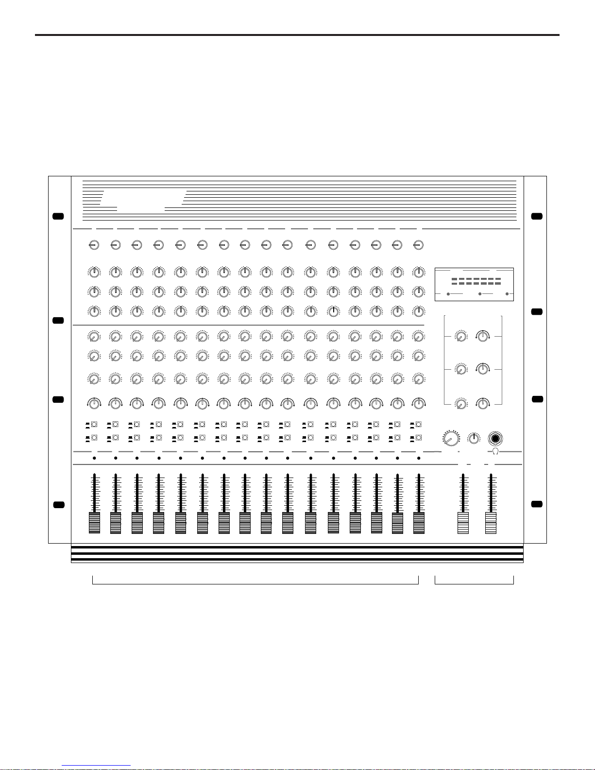
1: Input Trim (black) - This knob determines the input level of the connected
mic or line signal. Continuously adjustable from +4 dB to -50 dB, the input trim is
at unity gain (no boost or cut) when set to the 0 position. The input signal is
boosted when the knob is turned to the right of 0 and attenuated when turned to
the left of 0. For information on how to properly set this for each channel, see the
section on page 12 entitled “Setting The Correct Gain Structure.”
2: Equalizer (blue) - These knobs determine the amount of boost or attenuation
in each of three frequency areas. The “High”and “Low”frequency knobs provide
15 dB of cut or boost at 10 kHz and 80 Hz, respectively, with shelving-type
control. The “Mid”frequency knob provides 12 dB of cut or boost at 800 Hz, with
a bell (peaking) curve. A center detent in each knob (at the 12 o’clock position)
indicates no boost or attenuation (that is, flat response). As each knob is turned
clockwise from the center detent position, the frequency area is boosted; as it is
turned counterclockwise from the center detent position, the frequency area is
attenuated. For more information on the application of EQ, see the “Using
Equalization”section on page 19 of this manual.
3: Auxiliary sends (light gray) - These knobs allow you to route signal to any of
the MPL 1640’s three monophonic auxiliary outputs. These are typically used to
create submixes (for example, a monitor mix or headphone cue mix) or to feed
signal from single or multiple channels to outboard effects devices. At the 0 posi-
tion, the send signal is routed with unity gain (that is, no boost or attenuation).
As each knob is turned clockwise from the 0 position, the signal is boosted; as it
is turned counterclockwise from the 0 position, it is attenuated. At the fully
counterclockwise “-∞”position, the send signal is infinitely attenuated—that is,
no signal is routed. At the fully clockwise “+10”position, the send signal is routed
with 10 dB of gain. Auxiliary send 1 is always pre-fader; that is, the level of the
send signal is determined solely by the channel’s input trim and is unaffected by
its fader position and EQ settings. Auxiliary sends 2 and 3 are post-fader; that is,
the level of the send signal is determined by the channel’s input trim, its EQ
settings, and the position of its fader.
4: Pan (white) - This knob allows you to place each channel’s signal anywhere
in the left-right stereo spectrum, while keeping the overall signal level constant.
When the knob is placed at its center (detented) position, the signal is sent
equally to both left and right outputs. When moved left of center, less signal is
sent to the right output (making the sound appear left of center) and when moved
right of center, less signal is sent to the left output (making the sound appear
right of center). To route a signal hard left or right, place the pan knob either fully
counterclockwise or fully clockwise. See the “Using Pan”section on page 18 of
this manual for more information.
5: PFL switch (gray) - When pressed in, the channel is soloed in PFL (Pre-Fade
Listen) mode, affecting headphone monitoring only. For more information, see
the section on page 22 entitled “Using PFL Solo.”
4
+4 -50
INPUT TRIM
0
-10
-15 +15
HIGH
0
-12 +12
MID
0
-15 +15
LOW
0
+10
AUX 1
0
−∞
+10
AUX 2
0
−∞
+10
AUX 3
0
−∞
PFL
BUS
ON
OFF
3 / 4
L / R
1
-∞
dB
PEAK
+15
0
R
PAN
L
1
MUTE
1
2
3
4
5
6
7
8

Guided Tour - Channel
6: Bus switch (gray) - When up, the channel’s signal is routed to the Main L/R
faders (as described on page 7) and then on to the MPL 1640 Main Mix output
jacks (as described on page 8). When pressed in, the channel’s signal is
removed from the Main L/R output and is instead routed to the 3/4 Level knob
(as described on page 6) and then to the 3L/4R output jacks (as described on
page 8). If you don‘t have anything connected to the MPL 1640 Bus 3/4 output
jacks, this switch can be used for channel muting. See the “Using Bus 3/4”
section on page 17 for more information.
7: Peak LED (red) - This warning light indicates an overload situation. It lights
whenever a channel’s signal is 5 dB short of clipping. To stop it from lighting
(and to eliminate the accompanying sonic distortion), turn down the channel’s
Trim knob (see #1 on the previous page) or reduce the amount of equalization
boost. See the “Setting the Correct Gain Structure”and “Using Equalization”
sections on pages 12 and 19 for more information.
8: Channel fader (gray with a blue line) - This linear slider determines the signal
level being sent to the main output as well as affecting the signal level being
routed to Aux sends 2 and 3 (which are post-fader; Aux 1 is always pre-fader).
In practice, you will use the channel faders to continuously adjust the levels of
the various signals being blended together by the MPL 1640. The detented “0”
position of the fader indicates unity gain (no level attenuation or boost). Moving
the fader down from the “0”position (towards “-∞”) causes the signal to be atten-
uated (at the very bottom, it is attenuated infinitely—in other words, there is no
sound). Moving it up from the “0”position (towards “+15”) causes the signal to
be boosted by as much as 15 dB.
For best signal-to-noise ratio, all faders for channels carrying signal should gen-
erally be kept at or near the “0”detented position. Channels that are unused
should have their faders kept all the way down at their "-∞" (minimum) level. See
the “Setting the Correct Gain Structure”section on page 12 for more information.
5

Guided Tour - Main Section
1: Meter - This seven-segment bar meter shows the continuous output level of
the Main L/R stereo output. For optimum signal-to-noise ratio, try to adjust all
levels so that program material is usually at or around 0 VU, with occasional but
not steady excursions to the red +3 or +6 segments. See the “Setting the
Correct Gain Structure”section on page 12 for more information.
2: Meter LEDs - These show the status of various conditions within the MPL
1640. The bottom left LED (labeled “PFL”) lights steadily red whenever one or
more channels is soloed. The bottom center LED (labeled “Phantom”) lights
steadily red when Phantom power is being supplied to all mic connectors (see #1
on page 8 of this manual for more information). The bottom right LED (labeled
“Power”) lights steadily red whenever the MPL 1640 is powered on.
3: Stereo Auxiliary Return Level (green) - These knobs determine the input
level of signal arriving via the MPL 1640’s three stereo Auxiliary returns. Each
return is at unity gain (no boost or attenuation) when set to the 0 position. The
input signal is boosted when the knob is turned to the right of 0 and attenuated
when turned to the left of 0. When turned fully clockwise (to the “+20”position),
the return signal is boosted by 20 dB; when turned fully counterclockwise (to the
“-∞”position), the return signal is infinitely attenuated—that is, there is no sound.
For information on how to properly set these, see the sections on pages 12 and
20 entitled “Setting the Correct Gain Structure”and “Using the Auxiliary Sends
and Returns.”
4: Stereo Auxiliary Return Balance (dark gray) - These knobs determine the
relative levels of the left and right input signals connected to the MPL 1640’s
three stereo Auxiliary returns. When the knob is placed at its center (detented)
position, both left and right input signals for that Aux return are at equal strength.
When moved left of center, the left input signal remains at the same strength but
the right input signal is attenuated; when the knob is moved right of center, the
right input signal remains at the same strength but the left input signal is attenu-
ated. When placed fully counter-clockwise, only the left input signal is heard
(panned hard left); when placed fully clockwise, only the right input signal is
heard (panned hard right). These “radical”positions are useful when you are
using a stereo Aux return as two mono returns—see the “Using the Auxiliary
Sends and Returns”section on page 20 for more information.
When only the left input of an Aux return is connected, its Balance knob func-
tions as a constant level Pan control, allowing you to continuously place the
incoming signal anywhere in the left-right stereo field.
5: 3/4 Level (green) - This knob determines the final output level of the Bus 3/4
signal. We made this knob extra big so you won’t miss it even under low-light
performance conditions. Signals from all channels that have their Bus
switch (see page 5) set to the “3/4”position are routed here prior to being sent to
the rear panel 3/4 output jacks (as described on on page 8). The center detent-
ed “0”position of the knob indicates unity gain (no level attenuation or boost).
Moving the knob counterclockwise from the “0”position (towards “-∞”) causes
the signal to be attenuated (at the fully counterclockwise position, it is attenuated
infinitely—in other words, there is no sound). Moving the knob clockwise from
the “0”position (towards “+15”) causes the signal to be boosted by as much as
15 dB. For more information, see the “Using Bus 3/4”section on page 17 of this
manual.
LR
+20
RETURN 1 LEVEL
0
−∞
+20
0
−∞
RETURN 2 LEVEL
+20
0
−∞
RETURN 3 LEVEL
R
BALANCE
L
R
BALANCE
L
R
BALANCE
L
HEADPHONES
3 - 4
LEVEL
010
−∞ +15
STEREO AUXILIARY RETURNS
STERE0 PFL
LEFT
RIGHT
PFL PHANTOM POWER
-20 -10 -6 -3 0+3+6
-20 -10 -6 -3 0+3+6
16 CHANNEL AUDIO MIXER
MPL 1640
-∞
dB
+15
0
MAIN
1
2
4
3
5
6
7
8
0
6

Guided Tour - Main Section
6: Headphones control (black) - This knob sets the level of the signal sent to
the headphone jack (see #7 below). WARNING: To avoid possible damage
to connected headphones (or, worse yet, to your ears!), always turn this all
the way off (to the fully counterclockwise “0” position) before plugging in a
pair of headphones—then raise the level slowly while listening. The
Headphones control has no effect on the final Main Mix or Bus 3/4 output levels.
7: Headphone jack - Connect any standard stereo headphones to this jack (via
a standard 1/4”TRS plug) for private monitoring of the main stereo output. The
built-in MPL 1640 headphone preamp delivers 150 mw at 30 ohms.
8: Main L/R Faders (white with blue line) - These linear sliders determine the
relative level of the two Main Left/Right outputs just prior to being sent to the rear
panel Main Mix output jacks (as described on page 8). The “0”(detented)
position of each fader indicates unity gain (no level boost or attenuation).
Moving the fader below this position (towards the “-∞”dB position) causes the
signal to be attenuated (at the very bottom, it is attenuated infinitely—in other
words, there is no sound). Moving it above this position (towards the “+15”
position) causes the signal to be boosted by as much as 15 dB.
For best signal-to-noise ratio, both Main L/R faders should generally be kept at
or near the detented 0 level. See the “Setting The Correct Gain Structure”
section on page 12 of this manual for more information.
7

Guided Tour - Rear Panel
1: Phantom switch - When this switch is turned on, the MPL 1640 delivers 48 volts of
phantom power to pins 2 and 3 of all XLR microphone connectors (channels 1 - 10).
WARNING: Only turn this on or off with the MPL 1640 powered down. Before turn-
ing phantom power on, be sure to disconnect all non-microphone signal sources (such as
direct injection boxes) from the XLR mic jacks. Although phantom power will have no
adverse affect on connected dynamic microphones, it should be used only when one or
more condenser microphones are connected to the MPL 1640 (refer to the owners manu-
al of your microphone to determine whether or not it requires 48 volts phantom power).
If you’re not completely certain that one or more connected mics require 48 volts
phantom power, leave this switch OFF.
2: Power switch - This is what you use to turn the MPL 1640 on and off. To avoid
potential damage to your speakers, turn the mixer on before you turn on any connected
power amps—and turn it off after the power amps are turned off.
3: AC Input - Connect the supplied standard 3-pin “EEC”plug here.
4: Fuse sled - Fuse ratings are 1 amp for 115 V usage and .5 amp for 230 volt usage.
See Appendix A on page 28 for more information.
5: Main Mix Out (L,R) - These are the MPL 1640’s main outputs. You’ll usually use
these to connect the MPL 1640 to a power amplifier or to a tape recorder. These jacks
are electronically balanced, so use balanced three-conductor cabling and 1/4" TRS plugs
wherever possible (unbalanced two-conductor plugs can also be inserted into these jacks,
but you’ll get better signal quality and less noise and hum if you use balanced lines). See
the “Connecting the MPL 1640”section on page 10 for more information.
6: 3L/4R Out - These are the MPL 1640’s secondary outputs. The 3/4 Out jacks are
unbalanced, accepting standard two-conductor 1/4" plugs. For this reason, it is generally
preferable to use the Main Mix outputs when only two outputs are required. See the
“Using Bus 3/4”section on page 17 for more information.
7: Main Mix Insert (L,R) - Use these to insert an external in-line effects processor (such
as outboard equalizer, compressor/limiter or noise gate) into the Main Mix output in an
“effects loop”configuration. These jacks accept 1/4" TRS plugs, with the ring carrying the
send signal and the tip carrying the return signal. Normally, this will be connected to a
Y-cable; see the “Connecting The MPL 1640”section on page 10 for more information
and a wiring diagram.
8
1
2
3
1
2
3
1
2
3
1
2
3
1
2
3
CH 1CH 2
CH 3CH 4
CH 5
CH 1
CH 2CH 3
CH 4CH 5
CH 6
CH 7CH 8CH 9CH 10CH 11CH 12CH 13CH 14CH 15CH 16
ON
OFF
1
2
3
CH 6
1
2
3
CH 7
1
2
3
CH 8
1
2
3
CH 9
1
2
3
CH 10
CH 11
CH 12CH 13CH 14
CH 15
CH 16
115
CAUTION
RISK OF ELECTRIC SHOCK
DO NOT OPEN
!
ON
OFF
~115V /230V
50/60Hz 42W
MAIN MIX OUT
(BALANCED 600Ω
+ 4dB)
P
O
W
E
R
PHANTOM
SERIAL
NUMBER
AVIS:
RISQUE DE CHOC ELECTRIQUE
NE PAS OUVRIR.
DO NOT EXPOSE THIS EQUIPMENT
TO RAIN OR MOISTURE.
XLR
1 GND
2 +
3 -
MPL 1640
16 CHANNEL
AUDIO MIXER
TIP RING SLEEVE
TIP +
RING -
SLEEVE GND
ASSEMBLED IN R.O.K.
SAMSON TECHNOLOGIES CORP., NEW YORK, U.S.A.
SAMSON
L
CHANNEL INSERT (TIP RETURN - RING SEND)
AUX 1AUX 2
3L - 4RMAIN MIX
R
L
AUX 3
AUX 3 AUX 2 AUX 1
AUX RETURN (UNBAL.2KΩ
+ 4dB)
R
RR LLL
(BALANCED - 50dB TO + 4dB)
MIC INPUT
R
3L - 4R(UNBAL.2KΩ +4dB)
BUS INSERT AUX OUT
(UNBAL.2KΩ +4dB) LINE INPUT (BALANCED 10 KΩ - 40dB
TO + 4dB)
1
2 3 4
5 6
7810 11
1213
14
9

Guided Tour - Rear Panel
8: Bus Insert - Use these to insert an external in-line effects processor (such as out-
board equalizer, compressor/limiter or noise gate) into the Bus 3/4 output in an “effects
loop”configuration. These jacks accept 1/4" TRS plugs, with the ring carrying the send
signal and the tip carrying the return signal. Normally, this will be connected to a
Y-cable; see the “Connecting The MPL 1640”section on page 10 for more information
and a wiring diagram.
9: Aux Outs - These unbalanced 1/4" outputs allow you to route signal from each of the
three discrete Aux sends to external devices such as effects processors. Aux send 1 is
pre-fader and pre-EQ, while Aux sends 2 and 3 are post-fader and post-EQ. See the
“Using the Auxiliary Sends and Returns”section on page 20 for more information.
10: Aux Returns - These unbalanced 1/4" inputs allow you to route signal from exter-
nal devices such as effects processors to any of the three stereo Aux Returns. See the
“Using the Auxiliary Sends and Returns”section on page 20 for more information.
11: Channel Inserts (1 - 12) - Use these to insert external in-line effects processors
(such as outboard equalizers, compressor/limiters or noise gates) into channels 1 - 12 in
an “effects loop”configuration. These jacks accept 1/4”TRS plugs, with the ring
carrying the send signal and the tip carrying the return signal. Normally, this will be
connected to a Y-cable; see the “Connecting The MPL 1640”section on page 10 for
more information and a wiring diagram.
12: Line Inputs (1 - 16) - Use these standard balanced 1/4" jacks to connect line-level
sources such as synthesizers, drum machines, CD players, tape decks, or effects
processors to any of the MPL 1640’s input channels. All channel line input jacks are
electronically balanced, so you should use balanced three-conductor cabling and plugs
wherever possible (unbalanced two-conductor plugs can also be inserted into these
inputs, but you’ll get better signal quality and less outside noise and hum if you use
balanced lines). See the “Connecting The MPL 1640”section on page 10 for more
information. WARNING: Do not connect a channel’s line input if you already have
something connected to its mic input; each channel is designed to accept only
one or the other.
13: XLR Mic Inputs (1 - 10) - Use these standard XLR jacks to connect microphones to
any of the MPL 1640’s first ten channels (channels 1 - 10). These are intended to
accept signal from low-level, low-impedance mics but can also be used for signal from
other sources (such as direct injection boxes) if the channel’s Trim control is turned
down. WARNING: Do not turn Phantom power on if signal sources other than
microphones are connected to any of these inputs. Also, do not connect a chan-
nel’s mic input if you already have something connected to its line input; each
channel is designed to accept only one or the other.
14: 1/4" Mic Inputs (11 - 16) - Use these standard balanced 1/4" jacks to connect
microphones to any of the MPL 1640’s last six channels (channels 11 - 16). These are
intended to accept signal from low-level, low-impedance mics but can also be used for
signal from other sources (such as direct injection boxes) if the channel’s Trim control is
turned down. WARNING: Do not connect a channel’s mic input if you already have
something connected to its line input; each channel is designed to accept only
one or the other.
9

Connecting The MPL 1640
The actual connections you’ll make to and from the MPL 1640 will vary accord-
ing to the environment you use it in and the particular equipment you have. In
the “Applications”sections at the conclusion of this manual (pages 24 - 27),
you’ll find some suggested setups. Here we present a few basic rules concern-
ing MPL 1640 connections that will apply in pretty much all situations:
•In general, it’s best to make all connections with the MPL 1640 and all
power amplifiers turned off. If you must make connections with the power
on, make sure that both the Main Mix and 3/4 output levels are completely
down. Whenever powering down, turn both output levels completely down
and then turn off all power amps first. Wait a few seconds for their power
supplies to discharge and then turn off all connected equipment, turning the
MPL 1640 off last.
•Try to use balanced connectors and cabling wherever possible. These kind
of connections do a better job of rejecting extraneous noise and hum and
generally provide a cleaner signal. Although the MPL 1640 will accept
unbalanced connectors throughout, it specifically provides electronically
balanced connectors for all sixteen mic and line inputs and for its Main Mix
outputs. The wiring diagram below shows how 1/4" TRS (Tip/Ring/Sleeve)
plugs should be wired for use with these inputs and outputs:*
Unbalanced cables use standard 1/4" phone plugs, wired as follows:
•Make one connection at a time and then monitor the incoming signal. If you
hear a distinct hum or buzz, you may have a grounding problem with that
particular device. See the section on page 15 entitled “Grounding
Techniques”for information on how to avoid grounding problems.
•NEVER connect a microphone and line level input to the same channel
simultaneously—use one or the other. You can have some channels con-
nected to microphones and others to line level signals (for example, you
might want to plug mics into channels 1 - 6 and line level signals into chan-
nels 7 - 10)—just don’t have both kinds of inputs connected to the same
channel. The diagram below shows how your XLR mic connectors should
be wired:*
* You’ll also find this information silk-screened on the MPL 1640 rear panel.
10
TIP +
GROUND
RING -
RING
TIP
SLEEVE
+ SIGNAL
GROUND
+ SIGNAL
GROUND
3 - SIGNAL
1 GROUND
2 + SIGNAL
TO MIXER

•In addition to the sixteen monophonic input channels, there are three “hid-
den”(or at least not so obvious) stereo inputs to the MPL 1640; these are
the Auxiliary returns.* Use these whenever you want to bring in a stereo
signal that will not need to be equalized. Also bear in mind that the three
stereo Auxiliary returns can also be used as six monophonic returns (with
the Aux return Balance controls giving you the ability to adjust the relative
levels of the left/right inputs). For example, if you’re using the MPL 1640 in
live performance to drive a mono PA system, you may not need to take the
stereo returns from outboard effects processors.
•Because Aux 1 is pre-fader, you should use it only where a pre-fade mix is
required. For example, in a recording situation, Aux 1 is optimum for head-
phone cueing or for driving a secondary monitor (such as a studio room
monitor). In live performance, Aux 1 can be used to route signal to an
onstage monitor system so that the signal the performers hear is indepen-
dent of the house mix.
•Signals that are likely to require “in-line”processing (such as compression/
limiting or expansion/noise gating) should be connected to channels 1 - 12,
since these channels provide an insert connection.
Insert cables (sometimes called “Y-cables”) should terminate in standard 1/4”
TRS jacks (tip to return and ring to send), wired as follows:**
* The MPL 1640 Aux returns are hardwired to the Main Mix outputs; there is no
provision for routing their signal to the Bus 3/4 outputs.
** You’ll also find this information silkscreened on the MPL 1640 rear panel.
11
Connecting The MPL 1640
TIP RETURN
GROUND
RING SEND
RING
TIP
SLEEVE

12
Setting up your MPL 1640 is a simple procedure which takes only a few minutes:
1. Remove all packing materials (save them in case of need for future service)
and decide where the unit is to be physically placed—it can be used on a
tabletop or mounted in any standard 19”rack, requiring 8 rack spaces.
2. Before even plugging the unit into an AC socket, begin by connecting the
MPL 1640 Main Mix outputs (or secondary 3L/4R outputs) into a switched-
off power amp and the amp into loudspeakers. It is never a good idea to
power up any amplifier that is not connected to loudspeakers.
3. Next, make all signal connections to the mic or line inputs of the various
channels and to the MPL 1640’s Aux sends and returns and insert points as
required. WARNING: Do not connect a channel’s line input if you already
have something connected to its microphone input, or vice versa; each
channel is designed to accept only one source or the other.
4. Bring all channel faders and the Main L/R faders completely down (to their
“-∞”setting) and turn the 3/4 Level knob fully counterclockwise (to its
“-∞”setting). Then connect the EEC main power cord and plug the MPL
1640 into any grounded AC socket.
5. Press the MPL 1640’s rear-panel Power switch. Once power is received,
the “Power”LED in the meter section will light up.
Setting the Correct Gain Structure
You’re now ready to establish the correct gain structure—the key to getting the
best performance from the MPL 1640, or from any mixer, for that matter. This is
a simple procedure that ensures optimum input and output levels so that no
unnecessary noise (caused by too low a signal) or overload distortion (caused by
too high a signal) is created. Here’s a step-by-step description of how to do so:
a Turn off the MPL 1640 and all connected power amplifiers. Set all power
amplifier volumes to minimum. On the MPL 1640, bring all channel faders
down to the bottom-most “-∞”position, and set both Main L/R faders to their
center detent “0”position. If any devices are connected to the secondary
3L/4R outputs, turn the 3/4 Level knob fully counterclockwise (to its “-∞”
setting).
b. Set all channel input trim knobs to their fully counterclockwise (+4) position.
c. Set all channel equalizer and pan knobs as well as all three Aux return
balance knobs to their center detent “0”positions.
d. Set all channel Aux send knobs and all three stereo Aux return level knobs
to their fully counterclockwise (“-∞”) position.
e. Turn on all devices connected to channel line inputs and Aux returns and
set their output level controls to unity gain or, if there is no unity gain indi-
cated on their output control, to maximum. If you’ve got outboard effects
processors connected to MPL 1640 Aux returns, make sure they are send-
ing completely “wet”(processed) signal, with no “dry”(unprocessed) signal
mixed in.
Setting Up and Using the MPL 1640
MAIN MIX OUT
(BALANCED 600Ω + 4dB)
L
R
SERVO- 240
SAMSON
115
ON
OFF
P
O
W
E
R

13
Setting Up and Using the MPL 1640
f. If any condenser microphones are connected to the MPL 1640, turn on the
Phantom switch.* Then turn on the MPL 1640—the Power LED in the
meter section will light up. Finally, turn on the power amplifier.
g. Play an instrument connected to one of the MPL 1640’s line inputs** and,
while doing so, raise the corresponding channel fader to the “0”position.
You should see the segment meter begin to move—adjust the input trim
control for that channel so that the “0”segment lights frequently and the
“+3”segment lights only occasionally. If the incoming signal seems too hot
even with the input channel trim all the way at its minimum (+4) setting, you
may need to lower the output level of the instrument, though this will rarely
occur. Conversely, if the signal is too low even with the input channel trim
all the way up, something's definitely wrong: in all likelihood, the connecting
audio cable is faulty.
h. Once you’ve set the optimum level in step (g) above, continue playing the
instrument and slowly raise the power amplifier volume until you get the
level you want to hear.
i. Repeat step (g) above for each instrument connected to the MPL 1640
channel line inputs.
j. The procedure for setting optimum microphone levels is virtually identical;
sing or speak into the mic at the level you expect to use in performance
while slowly raising the fader for that channel to its “0”position. Then adjust
the input trim control for that channel while watching the meter. You should
expect that microphone inputs will require rather more in the way of input
trim boost than line inputs.
k. If you have any outboard signal processors connected to the Aux send and
return jacks on the rear panel, follow this step. Because outboard effects
processors can sometimes be quite noisy, it’s particularly important to maxi-
mize the amount of signal being sent to them via the MPL 1640 Aux sends.
The idea is to drive these devices as hot as possible (short of overloading
them) and to then use the corresponding Aux return level to carefully adjust
the amount of processed signal being blended with the dry signal. To set
optimum Aux send levels, use a channel that has already had its gain struc-
ture adjusted in step (g) or (j) above. Turn all three Aux send knobs for that
channel to their “0”(unity gain) position and then play the instrument (or
sing into the microphone) connected to that channel. Adjust the input levels
of connected outboard effects processors so that their meter shows incom-
ing signal normally in the 0 VU range (with just occasional higher excur-
sions). Then it’s time to optimize the Aux return levels. While continuing to
play your instrument (or continuing to sing into the microphone), slowly raise
each Aux return level control until you hear the desired amount of
processed signal added to the dry signal. For more information, see the
“Using the Auxiliary Sends and Returns”section on page 20 of this manual.
* CAUTION: Before turning phantom power on, be sure to disconnect all non-
microphone signal sources (such as direct injection boxes) from the XLR
mic jacks (channels 1 - 10).
** If you're using an instrument such as electric guitar or bass, we recommend
that you connect it to the MPL 1640 with a direct injection box to ensure cor-
rect impedance.

14
Setting Up and Using the MPL 1640
l. The gain structure is now correctly set—you’ve optimized the level of all sig-
nals coming into and out of the MPL 1640, and the end result will be mini-
mum noise and distortion and maximum clean sound. You’ll now find that
the majority of your mixes can be accomplished with most channel faders
and both Main L/R faders at or near their 0 (unity gain) position and that the
channel peak LEDs rarely if ever light (remember, if they do light, it means
that something is distorting!). If you need to make adjustments to the over-
all level, use the volume control of your power amplifier.
Because this procedure sets the optimum input gain of all channels, it also
sets the correct gain structure when using the MPL 1640’s alternative Bus
3/4 outputs. Following this procedure, if you opt to route a channel’s signal
to the Bus 3/4 outputs (by pressing in that channel’s Bus switch), simply set
the main Bus 3/4 level knob to its detented 0 (unity gain) position for best
signal-to-noise ratio.
If you encounter difficulty with any aspect of setting up or using your MPL 1640,
you can call Samson Technical Support (516-932-1062) between 9 AM and
5 PM EST.

Grounding Techniques
Hum and buzz are the biggest enemies you face when interconnecting a large
number of different pieces of equipment to a central audio mixer. This is
because each piece of equipment may operate at a marginally different voltage
(this difference is called potential) and, when two devices at slightly different
potential are physically connected with audio cabling, the end result can be
nasty, extraneous noise (mind you, connecting two devices at very different
potential can result in a major electrical shock!).
However, there are several steps you can take to avoid grounding problems.
First, assuming you have an isolated electrical circuit that can handle the electri-
cal demands of your mixer and all connected audio equipment (these needs will
usually be modest), you should always plug your mixer and all connected equip-
ment into the same circuit. If possible, nothing else but this equipment should be
connected to that circuit. If you can’t do this, at least avoid plugging your mixer
and audio equipment into the same circuit that is already powering things like
heavy machinery, air conditioners, heaters, refrigerators, washing machines,
neon signs or fluorescent light fixtures. One particular culprit that will almost cer-
tainly create problems is the standard light dimmer (the kind that uses silicon
controlled rectifiers). Where low-level lighting is desired, use incandescent fix-
tures with autotransformer-type dimmers (sometimes called Variacs) instead—
these cost considerably more than the standard dimmer you’ll find at your local
hardware store, but are well worth the extra expense.
Three-prong plugs (such as the one used by the MPL 1640) should always be
used as is; don’t use adapters to lift the ground (unless you’re using a “star
ground network”—see below). If you hear hum or buzz from a device that uses
a two-prong plug (or an external two-prong AC/DC adapter), you can try revers-
ing the plug in the socket. If that doesn’t work, you may need to physically
ground that device’s chassis by connecting a wire (called a strap) from it to a
grounded piece of metal such as rack ears. Some pieces of equipment have a
screw-type ground post to which the strap can be connected; if not, you can
attach some kind of metallic binding post to the case itself. If you are using rack-
mounted audio devices and are experiencing hum or buzz, there's a simple test
to determine the source of the problem: while keeping all devices powered on
and connected with audio cabling, physically remove each device, one by one,
from the rack. If the hum disappears when a particular device is removed, you'll
know that that device is the culprit.
We also recommend that you use balanced audio cabling and connectors wher-
ever possible. The MPL 1640 provides electronically balanced inputs for all
channel mic and line inputs as well as for its Main Mix outputs. The wiring dia-
gram in the “Connecting The MPL 1640”section of this manual (page 10) shows
how 1/4”TRS (Tip/Ring/Sleeve) connectors should be wired for use with these
inputs and outputs.
In addition, you can minimize possible interference by planning your audio, elec-
trical, and computer cable runs so that they are as far apart from one another as
possible and so they don’t run parallel to one another. If they have to cross, try
to ensure that they do so at a 90°angle (that is, perpendicular to one another).
In particular, try to keep audio cabling away from external AC/DC adapters.
15

Grounding Techniques
If you’re using the MPL 1640 in a fixed location such as a recording studio, you
may want to invest the time and money into creating a star ground network. This
is by far the best technique for avoiding grounding problems. It involves using a
formidable ground source such as a cold water pipe or a copper spike driven into
the earth. A thick grounding cable is connected to that source and is then
brought to a central distribution point; from there, individual cables are connected
to each piece of equipment. This setup also requires that you lift the ground plug
of all three-prong AC connectors, so there is the possibility of danger if it is done
incorrectly. We strongly recommend that you contract with a qualified profes-
sional to carry out this or any kind of electrical work.
Another, less common problem you may encounter is that of oscillation (a ringing
tone), which, apart from being annoying, is potentially dangerous to your speak-
ers. This is generally caused either by poor outside wiring or by returning a sig-
nal out of phase (most commonly from an outboard signal processor). If audible
oscillation occurs, try isolating each input signal (by muting all other inputs or by
using the PFL soloing function). If one signal alone is causing the problem, you
should be able to eliminate the oscillation by reversing that signal’s phase (many
signal processors have a switch that allows you to do this).
16

Using Bus 3/4
In addition to the Main Mix stereo output, the MPL 1640 provides two indepen-
dent bus outputs (Bus 3/4).* A “bus”is simply a pathway through which a signal
can be routed. The provision of these secondary outputs makes it possible for
you to create two mixes simultaneously, so that some channels send signal to
the Main Mix output jacks (via the Main L/R faders) while other channels send
signal to the Bus 3 and 4 output jacks.**
For example, when using the MPL 1640 with a two-track digital or analog tape
recorder, you might want to connect the Main Mix outputs to the tape inputs
while connecting the Bus 3/4 outputs to the inputs of a stereo power amplifier.
If you then connect the tape outputs to two channels routed to Bus 3/4 (by
pressing in their Bus switches), you can then use the Main L/R faders to control
the signal level going to tape while using the Bus 3/4 level knob to control the
playback volume (you’ll want to set the tape recorder to monitor input signal
while recording). See the “Applications”section on page 24 of this manual for
more information.
If no equipment is connected to the rear panel Bus 3/4 output jacks, you can use
the MPL 1640 Bus switches to mute particular channels (that is, remove them
temporarily from the overall mix without having to change their fader position).
To do this, all you have to do is press in that channel’s Bus switch; when you do
so, the signal will be rerouted to the Bus 3/4 output jacks (which are not
connected to anything) and will be removed from the Main Mix you hear. To
restore the signal (that is, unmute it), all you have to do is press that channel’s
Bus switch again—since its fader hasn’t been moved, the sound will come back
at the same level as before.
* When only two outputs are required, the Main Mix outputs are preferable to the
Bus 3/4 outputs since they provide electronically balanced jacks.
** A channel cannot be routed to both the Main Mix and Bus 3/4 output jacks
simultaneously. Note also that the MPL 1640 Aux returns are hardwired to the
Main Mix outputs; there is no provision for routing their signal to the Bus 3/4
outputs.
17
MAIN MIX OUT
(BALANCED 600Ω + 4dB)
L
R
3L - 4R(UNBAL.2KΩ +4dB)
3 - 4
LEVEL
−∞ +15
0
BUS
3 / 4
L / R MUTE

18
Using Pan
The final Main output of the MPL 1640 is stereo—that is, there are two discrete
Main Mix output jacks, labeled “left”and “right,”which will normally route signal
(via a power amplifier) to two discrete speakers.* Because of this, you will usual-
ly be working with a stereo field that ranges from hard left to hard right. The Pan
control in each channel allows you to place each individual sound at any point
within this left-right field, while keeping the overall level constant.
You can use stereo panning creatively in a variety of ways: For example, you
might want to have guitars coming from one speaker and keyboards from anoth-
er, or you might use panning to “spread”the signal from a piano miked with two
microphones—one over the bass notes (panned left) and the other over the tre-
ble notes (panned right). By turning a Pan knob while a signal is present, the
sound appears to move in space (a process known as dynamic panning)—this
can be particularly effective when applied to sound effects.
In live performance, you may want to resist the temptation to pan anything com-
pletely hard left or right, since some members of the audience not seated in the
center of the venue may miss some signal altogether. In these circumstances,
you’re best to use modest panning, with signals routed no further than the 9
o’clock and 3 o’clock positions.
In the stereo Auxiliary return section, the Balance control allows you to adjust the
relative levels of the signals arriving at the left and right inputs. In Aux returns
where both inputs are connected, the left signal is automatically panned hard left
and the right signal is automatically panned hard right. The Balance knob con-
trols the relative levels of the paired input signals. When the knob is placed at its
center (detented) position, both the left and right signals are at equal strength.
When moved left of center, the left input signal remains the same but the right
input signal is attenuated; when the knob is moved right of center, the right input
signal remains the same but the left input signal is attenuated. When placed
fully counterclockwise, only the left input is heard (panned hard left); when
placed fully clockwise, only the right input is heard (panned hard right).
If you connect different monophonic devices (such as effects processors) to both
the left and right inputs of an Aux return, you can use the Aux Balance control to
blend the relative contribution of each. If you turn the Balance knob fully coun-
terclockwise, you’ll hear only the device connected to the left Aux input; if you
turn it fully clockwise, you’ll hear only the device connected to the right Aux input.
For more information, see the “Using the Auxiliary Sends and Returns”section
on page 20 of this manual.
* You can, of course, also use the MPL 1640 monophonically—simply route the
same signal to both the left and right outputs.
R
BALANCE
L
R
PAN
L
Table of contents
Other Samson Mixer manuals

Samson
Samson MIXPAD User manual

Samson
Samson MPL 1204 User manual

Samson
Samson SM10 User manual

Samson
Samson MPL 1502 User manual

Samson
Samson MDR MDR 6 User manual

Samson
Samson SASM4 User manual

Samson
Samson SM10 User manual

Samson
Samson SM4 User manual

Samson
Samson MDR 8 User manual

Samson
Samson Txm16 Installation instructions
Popular Mixer manuals by other brands

BluMill
BluMill SL-9831 manual

UNITED
UNITED CM-6058 instructions

KitchenAid
KitchenAid KP26M1XCE5 Instructions and recipes

Sunbeam
Sunbeam Mixmaster MX7700 Instruction/recipe booklet

Cuisinart
Cuisinart EVOLUTIONX RHM-100 Instruction/recipe booklet

Kenwood
Kenwood Titanium Chef Baker Weiss XL KVC65 instructions