FONESTAR MX-867RU User manual

INSTRUCTION MANUAL/MANUAL DE USUARIO/
MODE D’EMPLOI/MANUAL DE INSTRUÇÕES
MX-867RU
MATRIX MIXER
MEZCLADOR MATRICIAL
TABLE MIXAGE MATRICIELLE
MISTURADOR DE MATRIZ

EN
- 2 -
DESCRIPTION
- The model MX-867RU is a professional mixer/preamplifier with 5 input channels to 4 output zones with
independent volume control. It includes a USB/SD/MP3 player module with digital FM tuner. Specially
designed for PA applications with different loudspeaker zones which require independent volume control.
- It includes 2 balanced micro inputs/selectable lines and 2 auxiliary inputs, assignable to each output
channel. Phantom power supply in inputs 2 and 3, and priority for signal level in input 1.
CONTROLS AND FUNCTIONS
FRONT PANEL
FUSE
ZONE 4
REMOTE
VOL
REMOTE
VOL
BAL. OUTPUT BAL. OUTPUT
REMOTE
VOL
BAL. OUTPUT
REMOTE
VOL
BAL. OUTPUT
ZONE 3 ZONE 2 ZONE 1 FM ANT INPUT 4 INPUT 3 INPUT 2
GAIN
INPUT 1
PHANTOM
+48 V
GAIN
PHANTOM
+48 V
~115 V AC, 50/60 Hz FUSE: T1.6 A 250 V
~230 V AC, 50/60 Hz FUSE: T0.8 A 250 V
MULTIZONE MIXER / PREAMPLIFIER
MX-867RU
MIC
Z
PRIORITY
ON / OFF
Z Z
INPUTS ZONES
1 2 3 4 Z1
SIG SIG SIG SIG
FM RADIO & MP3 PLAYER
Z2 Z3 Z4 INPUTS MONITOR
VOL-
CH+
MODE
FM / MP3
EQ
SCAN
VOL+
INPUT 5
AUX
Z1
Z
ZZ2 Z3 Z4
MULTIZONE MIXER / PREAMPLIFIER MX-867RU
FM RADIO & MP3 PLAYER
VOL-
CH+
MODE EQ
SCAN
VOL+
a d e
b
1
1
2
2 3
5610
c f g h i
9
6
7
12
4
10 11 13 14
9
8
3
47
58
1.- Input 1 volume control.
2.- Priority ON/OFF: input 1 priority selector. Activates/deactivates the priority by level for the microphone
connected to this input.
3.- INPUT 1: dynamic microphone balanced input for channel 1, 6.3 mm jack connector.
4.- Inputs 2, 3 and 4 volume control.
5.- INPUT 2-3-4: these microswitches allow the corresponding input signal to be allocated to one or several
output zones. To allocate a zone, place the corresponding microswitch (1 to 4) in the ON position and
in that or those selected output zones the selected input will be heard.
6.- Z1, Z2, Z3, Z4: Zones 1 to 4 output level volume control.
7.- SIG: LED indicators which light up in green when a signal is detected in the corresponding output
zone.
8.- USB/SD/MP3 player module with digital FM tuner.
FUSE
ZONE 4
REMOTE
VOL
REMOTE
VOL
BAL. OUTPUT BAL. OUTPUT
REMOTE
VOL
BAL. OUTPUT
REMOTE
VOL
BAL. OUTPUT
ZONE 3 ZONE 2 ZONE 1 FM ANT INPUT 4 INPUT 3 INPUT 2
GAIN
INPUT 1
PHANTOM
+48 V
GAIN
PHANTOM
+48 V
~115 V AC, 50/60 Hz FUSE: T1.6 A 250 V
~230 V AC, 50/60 Hz FUSE: T0.8 A 250 V
MULTIZONE MIXER / PREAMPLIFIER
MX-867RU
MIC
Z
PRIORITY
ON / OFF
Z Z
INPUTS ZONES
1 2 3 4 Z1
SIG SIG SIG SIG
FM RADIO & MP3 PLAYER
Z2 Z3 Z4 INPUTS MONITOR
VOL-
CH+
MODE
FM / MP3
EQ
SCAN
VOL+
INPUT 5
AUX
Z1
Z
ZZ2 Z3 Z4
MULTIZONE MIXER / PREAMPLIFIER MX-867RU
FM RADIO & MP3 PLAYER
VOL-
CH+
MODE EQ
SCAN
VOL+
a d e
b
1
1
2
2 3
5610
c f g h i
9
6
7
12
4
10 11 13 14
9
8
3
47
58
a.- USB/SD/MP3 player with digital FM radio tuner display.
b.- SD card memory slot.
c.- USB storage device slot.
d.- / : in PLAY mode, a short press of these buttons allows passing to the previous/next track.
A long press of these buttons allows fast forwarding/rewinding. In radio mode, it allows moving to
the previous/next frequency point with 0.1 MHz.
e.- VOL-/VOL+: USB/SD/MP3 player with digital FM radio tuner volume controls.
f.- MODE: allows selection of audio source among a USB storage device, an SD memory card or the
digital FM radio tuner.
g.- EQ-SCAN: in playback mode, it allows selection among the different equalizations available. In
radio mode, it allows automatic tuning of the FM radio stations. The tuning begins at the lowest
frequency and the stations are automatically stored in consecutive memory positions.

EN
- 3 -
h.- / / CH+: in playback mode, a short press of this button starts and pauses playback. A long
press allows playback selection among (RAN) random playback, (SIN) repeat a track, (FOL) repeat
folders, (ALL) repeat all. In radio mode, this button allows successive changes among the stations
stored during the automatic tuning.
i.- : button to switch off the USB/SD/MP3 player with FM tuner.
9.- FM/MP3: these microswitches allow the USB/SD/MP3 player with digital FM tuner module signal to be
allocated to one or several output zones. Place the corresponding microswitch (1 a 4) in the ON position
and the source will be heard in that or those zones.
10.- These microswitches allow the input signal INPUT 5 to be allocated to one or several output zones.
Place the corresponding microswitch (1 a 4) in the ON position and the source will be heard in that or
those zones.
11.- INPUT 5: auxiliary input, 3’5 mm jack connector.
12.- Z1-Z2-Z3-Z4: selectors to allocate one or several output zones to the headphones output. Press the
buttons to send the desired zone or zones to the headphones output.
13.- Headphones output, 6.3 mm stereo jack connector.
14.- Headphones output volume control.
REAR PANEL
FUSE
ZONE 4
REMOTE
VOL
REMOTE
VOL
BAL. OUTPUT BAL. OUTPUT
REMOTE
VOL
BAL. OUTPUT
REMOTE
VOL
BAL. OUTPUT
ZONE 3 ZONE 2 ZONE 1 FM ANT INPUT 4 INPUT 3 INPUT 2
GAIN
INPUT 1
PHANTOM
+48 V
GAIN
PHANTOM
+48 V
~115 V AC, 50/60 Hz FUSE: T1.6 A 250 V
~230 V AC, 50/60 Hz FUSE: T0.8 A 250 V
MULTIZONE MIXER / PREAMPLIFIER
MX-867RU
MIC
Z
PRIORITY
ON / OFF
Z Z
INPUTS ZONES
1 2 3 4 Z1
SIG SIG SIG SIG
FM RADIO & MP3 PLAYER
Z2 Z3 Z4 INPUTS MONITOR
VOL-
CH+
MODE
FM / MP3
EQ
SCAN
VOL+
INPUT 5
AUX
Z1
Z
ZZ2 Z3 Z4
MULTIZONE MIXER / PREAMPLIFIER MX-867RU
FM RADIO & MP3 PLAYER
VOL-
CH+
MODE EQ
SCAN
VOL+
a d e
b
1
1
2
2 3
5610
c f g h i
9
6
7
12
4
10 11 13 14
9
8
3
47
58
1.- AC power supply socket.
2.- Mixer/Preamplifier on/off switch.
3.- ZONE 1-ZONE 4 REMOTE VOL: outputs for remote control of output zones volume. Connect a
potentiometer in the desired zones to control the volume remotely. For more information, consult the
section Instructions for Use.
4.- ZONE 1-ZONE 4 BAL. OUTPUT: balanced line level outputs for zones Z1 to Z4, XLR connectors.
5.- FM ANT: FM antenna input.
6.- INPUT 4: auxiliary input, 2 x RCA connectors.
7.- INPUT 2-INPUT 3: microphone/line balanced inputs, combo connector (XLR and 6.3 mm jack).
8.- PHANTOM +48V: phantom power supply selector +48 V. Activate this selector when connecting an
electret condenser microphone to the input which requires phantom power supply (48 V between pins
2 and 3 of the XLR connector).
9.- GAIN: INPUT 2 and INPUT 3 sensitivity level. Allows the input sensitivity to be adjusted according to the
required level. If a microphone is being connected, set the control at its minimum level. If connecting
to a line level input, set the control approximately halfway. Adjust the control until an ideal sensitivity is
achieved.
10.- INPUT 1: dynamic microphone balanced input, combo connector (XLR and 6.3 mm jack).

EN
- 4 -
INSTRUCTIONS FOR USE
INPUT CHANNEL ALLOCATION TO OUTPUT ZONES
- The input channels INPUT 2 to 5 and the USB/SD/MP3 player with digital FM tuner module can be
allocated independently to one or several output zones ZONE 1 to ZONE 4.
FUSE
ZONE 4
REMOTE
VOL
REMOTE
VOL
BAL. OUTPUT BAL. OUTPUT
REMOTE
VOL
BAL. OUTPUT
REMOTE
VOL
BAL. OUTPUT
ZONE 3 ZONE 2 ZONE 1 FMANT INPUT 4 INPUT 3 INPUT 2
GAIN
INPUT 1
PHANTOM
+48 V
GAIN
PHANTOM
+48 V
~115 V AC, 50/60 Hz FUSE: T1.6 A 250 V
~230 V AC, 50/60 Hz FUSE: T0.8 A 250 V
MULTIZONEMIXER / PREAMPLIFIER
MX-867RU
MIC
Z
PRIORITY
ON / OFF
Z Z
INPUTS ZONES
1 2 3 4 Z1
SIG SIG SIG SIG
FM RADIO & MP3 PLAYER
Z2 Z3 Z4 INPUTS MONITOR
VOL-
CH+
MODE
FM / MP3
EQ
SCAN
VOL+
INPUT 5
AUX
Z1
Z
ZZ2 Z3 Z4
MULTIZONE MIXER / PREAMPLIFIER MX-867RU
ZONE
2
3
1
10 kΩ - 100 kΩ
POTENCIOMETRE
MIC
PRIORITY
ON / OFF
1
ON OFF
231
- Using the microswitches 1 to 4, you can select the zone to which the input channel signal will be sent.
Place the corresponding microswitch in the ON position to send that input signal to the desired zone.
For example, if you want input channel 3 to be heard in zones 1 and 2, microswitches 1 and 2 of INPUT
3 must be set in the ON position. If you want the USB/SD/MP3 player with digital FM tuner to be heard in
zones 1 and 4, the microswitches 1 and 4 of the USB/SD/MP3/FM module must be set in the ON position
INPUT PRIORITY
- The priority function automatically reduces the level of the inputs with lower priority so that the message
broadcast by those of higher priority can be clearly heard.
- In this case, the input with maximum priority is the dynamic microphone input INPUT 1 and it is activated
by signal level. To activate the priority function, the PRIORITY ON/OFF button located on the front panel
of the device should be pressed.
FUSE
ZONE 4
REMOTE
VOL
REMOTE
VOL
BAL. OUTPUT BAL. OUTPUT
REMOTE
VOL
BAL. OUTPUT
REMOTE
VOL
BAL. OUTPUT
ZONE 3 ZONE 2 ZONE 1 FMANT INPUT 4 INPUT 3 INPUT 2
GAIN
INPUT 1
PHANTOM
+48 V
GAIN
PHANTOM
+48 V
~115 V AC, 50/60 Hz FUSE: T1.6 A 250 V
~230 V AC, 50/60 Hz FUSE: T0.8 A 250 V
MULTIZONEMIXER / PREAMPLIFIER
MX-867RU
MIC
Z
PRIORITY
ON / OFF
Z Z
INPUTS ZONES
1 2 3 4 Z1
SIG SIG SIG SIG
FM RADIO & MP3 PLAYER
Z2 Z3 Z4 INPUTS MONITOR
VOL-
CH+
MODE
FM / MP3
EQ
SCAN
VOL+
INPUT 5
AUX
Z1
Z
ZZ2 Z3 Z4
MULTIZONE MIXER / PREAMPLIFIER MX-867RU
INPUT 1
PHANTOM
PHANTOM
MIC
PRIORITY
ON / OFF
INPUTS
1
INPUTS
ZONE
2
3
1
10 kΩ - 100 kΩ
POTENCIOMETRE
MIC
PRIORITY
ON / OFF
1
ON OFF
231
REMOTE CONTROL OF ZONES
- The remote control outputs REMOTE VOL allow the zone volume to be selected remotely with
a potentiometer installed in the output connector. The use of a 10 kΩ a 100 kΩ potentiometer is
recommended according to the following diagram:
FUSE
ZONE 4
REMOTE
VOL
REMOTE
VOL
BAL. OUTPUT BAL. OUTPUT
REMOTE
VOL
BAL. OUTPUT
REMOTE
VOL
BAL. OUTPUT
ZONE 3 ZONE 2 ZONE 1 FMANT INPUT 4 INPUT 3 INPUT 2
GAIN
INPUT 1
PHANTOM
+48 V
GAIN
PHANTOM
+48 V
~115 V AC, 50/60 Hz FUSE: T1.6 A 250 V
~230 V AC, 50/60 Hz FUSE: T0.8 A 250 V
MULTIZONEMIXER / PREAMPLIFIER
MX-867RU
MIC
Z
PRIORITY
ON / OFF
Z Z
INPUTS ZONES
1 2 3 4 Z1
SIG SIG SIG SIG
FM RADIO & MP3 PLAYER
Z2 Z3 Z4 INPUTS MONITOR
VOL-
CH+
MODE
FM / MP3
EQ
SCAN
VOL+
INPUT 5
AUX
Z1
Z
ZZ2 Z3 Z4
MULTIZONE MIXER / PREAMPLIFIER MX-867RU
ZONE
2
3
1
10 kΩ - 100 kΩ
POTENCIOMETRE
MIC
PRIORITY
ON / OFF
1
ON OFF
231
CONNECTION
- Make the connections with the amplifier and PA power amplifier of the system switched off and
disconnected from the power supply.
- Connect the audio devices or microphones desired to the corresponding inputs. If a dynamic microphone
is connected to inputs 2 or 3, set the sensitivity adjustment control GAIN close to its minimum. If a
condenser microphone is connected to inputs 2 or 3, also place this control in the same position and
activate the PHANTOM +48V selector.

EN
- 5 -
If a priority microphone is being connected, connect it to input 1.
If connecting to a line level source, set the sensitivity adjustment control to approximately halfway.
Adjust this control until an ideal sensitivity is achieved.
- Check that the input volume controls and the headphones output are set at their minimum.
- Power the mixer/amplifier mod. MX-867RU using the AC power supply.
- Once the connections have been made according to your needs, connect the devices to the power
supply and switch them on. After use, do not forget to switch off and disconnect the device from the
power supply.
FUSE
ZONE 4
REMOTE
VOL
REMOTE
VOL
BAL. OUTPUT BAL. OUTPUT
REMOTE
VOL
BAL. OUTPUT
REMOTE
VOL
BAL. OUTPUT
ZONE 3 ZONE 2 ZONE 1 FM ANT INPUT 4 INPUT 3 INPUT 2
GAIN
INPUT 1
PHANTOM
+48 V
GAIN
PHANTOM
+48 V
~115 V AC, 50/60 Hz FUSE: T1.6 A 250 V
~230 V AC, 50/60 Hz FUSE: T0.8 A 250 V
MULTIZONE MIXER / PREAMPLIFIER
MX-867RU
MX-867RU
PLAYER
POWER AMPLIFIER
TECHNICAL SPECIFICATIONS
MX-867RU
FEATURES Mixer/preamplifier.
Microphone input with paging priority.
Allocation matrix with 5 input channels to 4 output zones.
USB/SD player for MP3 files.
Digital FM radio tuner.
4 output zones with independent volume control.
Remote volume control for the zones.
Phantom power supply.
INPUTS 1 balanced microphone, 6.3 mm stereo jack, 12 mV RMS
1 balanced mic., combo (XLR and 6.3 mm jack), 12 mV RMS
2 balanced mics./lines combo (XLR and 6.3 mm jack) adjustable, 12 mV RMS and 640 mV RMS
1 stereo aux, 2 x RCA, 230 mV RMS
1 stereo aux, 3.5 m jack, 450 mV RMS
OUTPUTS 4 balanced zones, XLR, 2.5 V RMS
Remote volume control for the zones
1 stereo monitor, 6.3 mm jack, 1 V RMS
CONTROLS 4 micro allocation switches for zones 1 to 4
Inputs 1 to 4: volume control
Inputs 2 and 3: gain control
Zones 1 to 4: volume control
Monitor: volume control and zone selection
USB/SD player
FM tuner
RESPONSE 20-20,000 Hz
DISTORTION Harmonic: < 0.2 % to 1 kHz
S/N RATIO Microphones > 65 dB
Aux/Line > 80 dB
PHANTOM 48 V in mics. 2 and 3, selectable
PRIORITY Mic. 1 input level priority, selectable
POWER SUPPLY 230/115 V AC, 9 W
DIMENSIONS 483 x 44.5 x 200 mm depth. 1 U 19" rack

EN
- 6 -
ES
DESCRIPCIÓN
- El modelo MX-867RU es un mezclador/preamplificador profesional de 5 canales de entrada a 4 zonas
de salida con control independiente de volumen. Incluye un módulo reproductor USB/SD/MP3 con
sintonizador digital de radio FM. Indicado para aplicaciones de megafonía y sonorización con diferentes
zonas de altavoces que precisen un control independiente de volumen.
- Cuenta con 2 entradas balanceadas de micro/línea seleccionables y 2 entradas auxiliares, asignables
a cada canal de salida. Alimentación phantom en las entradas 2 y 3, y prioridad por nivel de señal en la
entrada 1.
CONTROLES Y FUNCIONES
PANEL FRONTAL
FUSE
ZONE 4
REMOTE
VOL
REMOTE
VOL
BAL. OUTPUT BAL. OUTPUT
REMOTE
VOL
BAL. OUTPUT
REMOTE
VOL
BAL. OUTPUT
ZONE 3 ZONE 2 ZONE 1 FM ANT INPUT 4 INPUT 3 INPUT 2
GAIN
INPUT 1
PHANTOM
+48 V
GAIN
PHANTOM
+48 V
~115 V AC, 50/60 Hz FUSE: T1.6 A 250 V
~230 V AC, 50/60 Hz FUSE: T0.8 A 250 V
MULTIZONE MIXER / PREAMPLIFIER
MX-867RU
MIC
Z
PRIORITY
ON / OFF
Z Z
INPUTS ZONES
1 2 3 4 Z1
SIG SIG SIG SIG
FM RADIO & MP3 PLAYER
Z2 Z3 Z4 INPUTS MONITOR
VOL-
CH+
MODE
FM / MP3
EQ
SCAN
VOL+
INPUT 5
AUX
Z1
Z
ZZ2 Z3 Z4
MULTIZONE MIXER / PREAMPLIFIER MX-867RU
FM RADIO & MP3 PLAYER
VOL-
CH+
MODE EQ
SCAN
VOL+
a d e
b
1
1
2
2 3
5610
c f g h i
9
6
7
12
4
10 11 13 14
9
8
3
47
58
1.- Control de volumen de la entrada 1.
2.- Priority ON/OFF: selector de prioridad de la entrada 1. Activa/desactiva la prioridad por nivel para el
micrófono conectado en esta entrada.
3.- INPUT 1: entrada balanceada de micrófono dinámico para el canal 1, conector jack 6’3 mm.
4.- Controles de volumen de las entradas 2, 3 y 4.
5.- INPUT 2-3-4: estos microinterruptores permiten asignar la señal de entrada correspondiente a una o
varias zonas de salida. Para asignar una zona, sitúe el microinterruptor correspondiente (1 a 4) en la
posición ON y por esa o esas zonas de salida se escuchará la entrada seleccionada.
6.- Z1, Z2, Z3, Z4: controles de volumen del nivel de salida de las zonas 1 a 4.
7.- SIG: indicadores luminosos que se encienden en color verde cuando se detecta señal en la zona de
salida correspondiente.
8.- Módulo reproductor USB/SD/MP3 con sintonizador radio FM.
FUSE
ZONE 4
REMOTE
VOL
REMOTE
VOL
BAL. OUTPUT BAL. OUTPUT
REMOTE
VOL
BAL. OUTPUT
REMOTE
VOL
BAL. OUTPUT
ZONE 3 ZONE 2 ZONE 1 FM ANT INPUT 4 INPUT 3 INPUT 2
GAIN
INPUT 1
PHANTOM
+48 V
GAIN
PHANTOM
+48 V
~115 V AC, 50/60 Hz FUSE: T1.6 A 250 V
~230 V AC, 50/60 Hz FUSE: T0.8 A 250 V
MULTIZONE MIXER / PREAMPLIFIER
MX-867RU
MIC
Z
PRIORITY
ON / OFF
Z Z
INPUTS ZONES
1 2 3 4 Z1
SIG SIG SIG SIG
FM RADIO & MP3 PLAYER
Z2 Z3 Z4 INPUTS MONITOR
VOL-
CH+
MODE
FM / MP3
EQ
SCAN
VOL+
INPUT 5
AUX
Z1
Z
ZZ2 Z3 Z4
MULTIZONE MIXER / PREAMPLIFIER MX-867RU
FM RADIO & MP3 PLAYER
VOL-
CH+
MODE EQ
SCAN
VOL+
a d e
b
1
1
2
2 3
5610
c f g h i
9
6
7
12
4
10 11 13 14
9
8
3
47
58
a.- Pantalla de información del reproductor USB/SD/MP3 con sintonizador FM.
b.- Puerto de conexión de tarjetas SD.
c.- Puerto de conexión de dispositivos de almacenamiento USB.
d.- / : en modo reproducción, una pulsación corta de estos botones permite pasar a la anterior/
siguiente canción. Una pulsación larga de estos botones permite realizar un retroceso/avance
rápido de la reproducción.
En modo radio, permiten pasar al anterior/siguiente punto de frecuencia con un paso de 0’1 MHz.
e.- VOL-/VOL+: controles de volumen del reproductor USB/SD/MP3 com sintonizador FM.
f.- MODE: permite seleccionar la fuente de audio entre un dispositivo de almacenamiento USB, una
tarjeta de memoria SD o el sintonizador de radio FM.

EN
- 7 -
ES
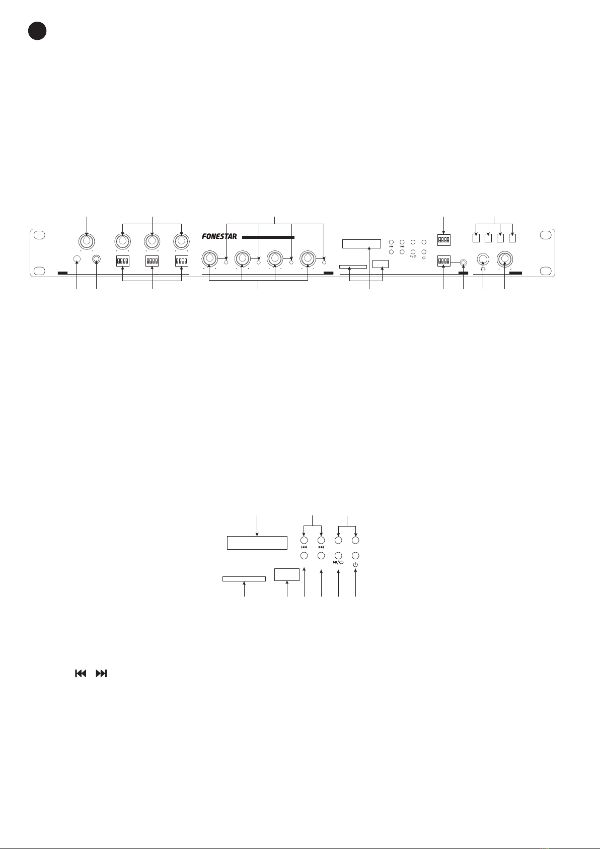
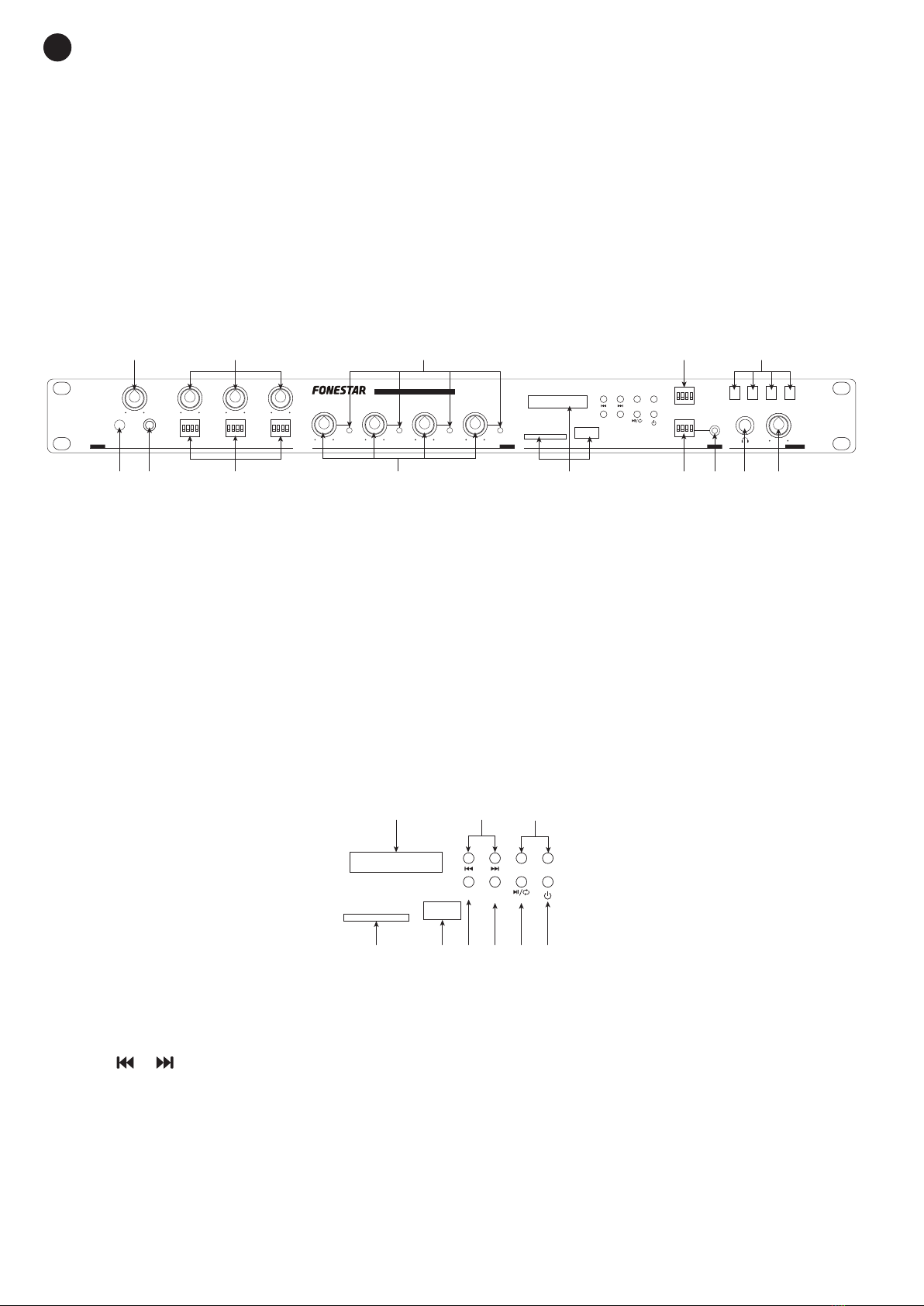
g.- EQ-SCAN: en modo reproducción, permite seleccionar entre las diferentes ecualizaciones
disponibles.
En modo radio, permite realizar una sintonización automática de las emisoras de radio FM. La
sintonización comenzará desde la frecuencia más baja y las emisoras se irán guardando en
posiciones de memoria consecutivas de manera automática.
h.- / / CH+: en modo reproducción, una pulsación corta de este botón permite iniciar y hacer
pausa en la reproducción. Una pulsación larga permite seleccionar el modo de reproducción entre:
reproducción aleatoria (RAN), repetir una pista (SIN), repetir carpetas (FOL), repetir todo (ALL).
En modo radio, este botón permite ir cambiando sucesivamente entre las emisoras guardadas
durante la sintonización automática.
i.- : botón para apagar el módulo reproductor USB/SD/MP3 con sintonizador FM.
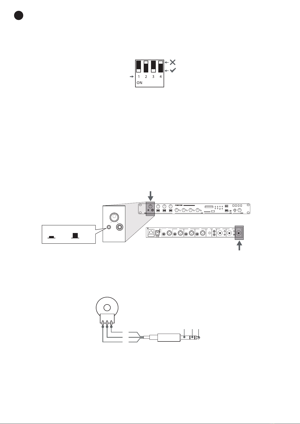
9.- FM/MP3: estos microinterruptores permiten asignar la señal del módulo reproductor USB/SD/MP3 con
sintonizador digital FM a una o varias zonas de salida. Sitúe el microinterruptor correspondiente (1 a 4)
en la posición ON y por esa o esas zonas de salida se escuchará esta fuente.
10.- Estos microinterruptores permiten asignar la señal de entrada INPUT 5 a una o varias zonas de salida.
Sitúe el microinterruptor correspondiente (1 a 4) en la posición ON y por esa o esas zonas de salida se
escuchará esa fuente.
11.- INPUT 5: entrada auxiliar, conector jack 3’5 mm.
12.- Z1-Z2-Z3-Z4: selectores para asignar una o varias zonas de salida a la salida de auriculares. Presione
los botones para enviar la zona o zonas deseadas a la salida de auriculares.
13.- Salida de auriculares, conector jack 6’3 mm estéreo.
14.- Control de volumen de la salida de auriculares.
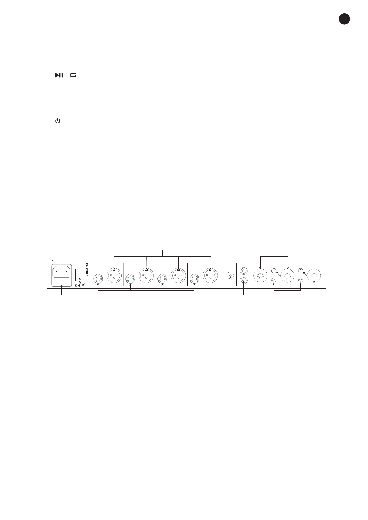
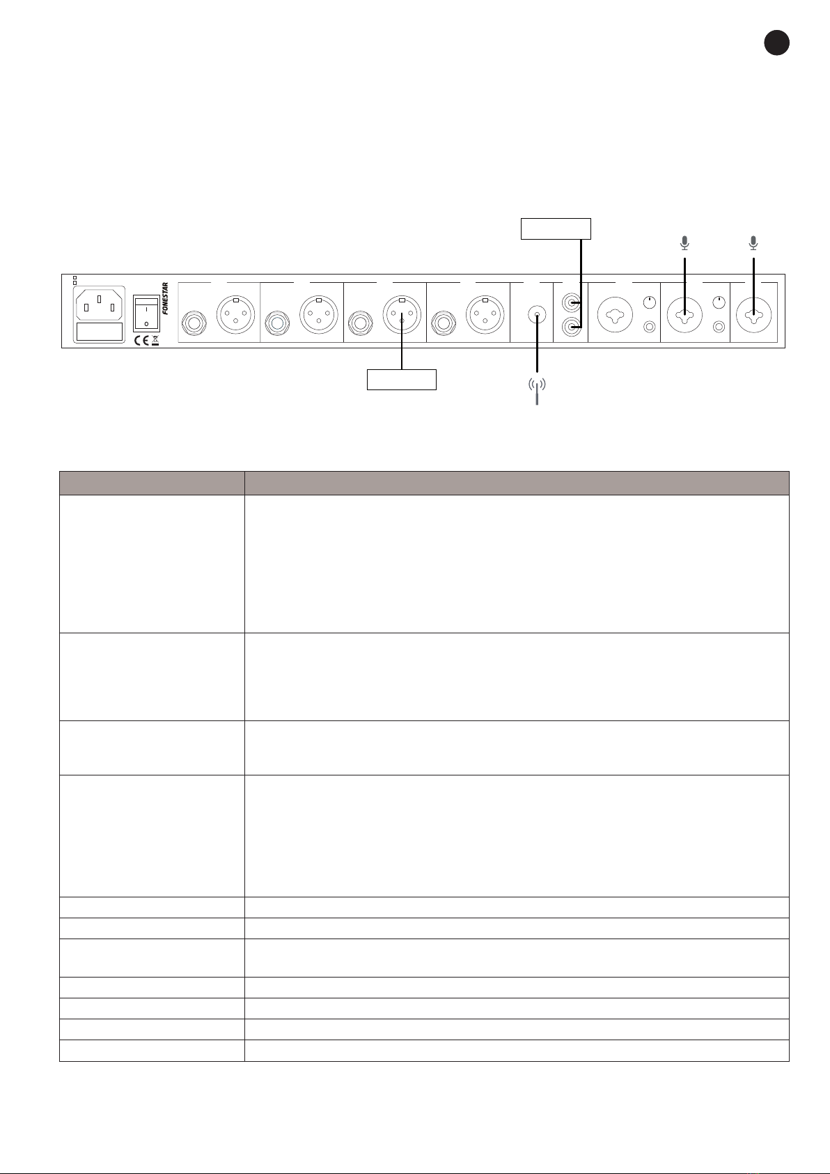
PANEL POSTERIOR
FUSE
ZONE 4
REMOTE
VOL
REMOTE
VOL
BAL. OUTPUT BAL. OUTPUT
REMOTE
VOL
BAL. OUTPUT
REMOTE
VOL
BAL. OUTPUT
ZONE 3 ZONE 2 ZONE 1 FM ANT INPUT 4 INPUT 3 INPUT 2
GAIN
INPUT 1
PHANTOM
+48 V
GAIN
PHANTOM
+48 V
~115 V AC, 50/60 Hz FUSE: T1.6 A 250 V
~230 V AC, 50/60 Hz FUSE: T0.8 A 250 V
MULTIZONE MIXER / PREAMPLIFIER
MX-867RU
MIC
Z
PRIORITY
ON / OFF
Z Z
INPUTS ZONES
1 2 3 4 Z1
SIG SIG SIG SIG
FM RADIO & MP3 PLAYER
Z2 Z3 Z4 INPUTS MONITOR
VOL-
CH+
MODE
FM / MP3
EQ
SCAN
VOL+
INPUT 5
AUX
Z1
Z
ZZ2 Z3 Z4
MULTIZONE MIXER / PREAMPLIFIER MX-867RU
FM RADIO & MP3 PLAYER
VOL-
CH+
MODE EQ
SCAN
VOL+
a d e
b
1
1
2
2 3
5610
c f g h i
9
6
7
12
4
10 11 13 14
9
8
3
47
58
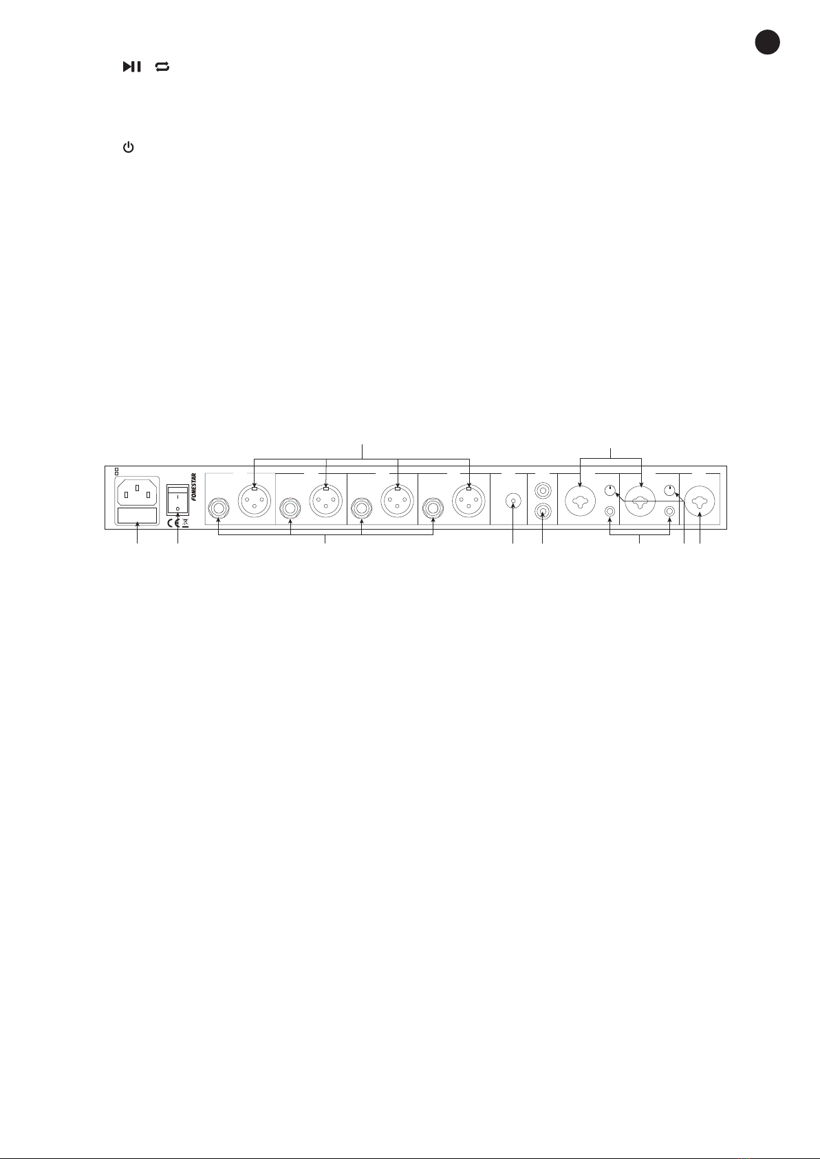
1.- Zócalo de alimentación CA.
2.- Interruptor de encendido/apagado del mezclador/preamplificador.
3.- ZONE 1-ZONE 4 REMOTE VOL: salidas para control remoto de volumen de las zonas de salida.
Conecte un potenciómetro en las zonas deseadas para controlar el volumen remotamente. Para más
información, consulte la sección Instrucciones de Uso.
4.- ZONE 1-ZONE 4 BAL. OUTPUT: salidas balanceadas de nivel de línea de las zonas Z1 a Z4, conectores
XLR.
5.- FM ANT: entrada de antena de FM.
6.- INPUT 4: entrada auxiliar, conectores 2 x RCA.
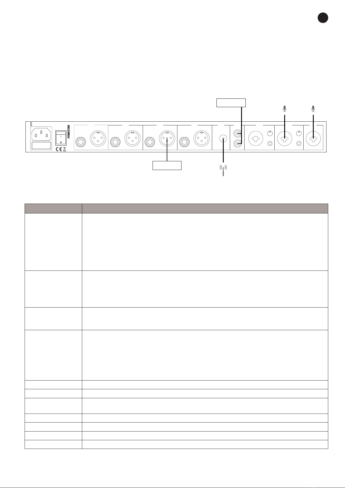
7.- INPUT 2-INPUT 3: entradas balanceadas de micrófono/línea, conector combo (XLR y jack 6’3 mm).
8.- PHANTOM +48 V: selector de nivel de alimentación phantom +48 V. Active este selector cuando
conecte a la entrada un micrófono de condensador electret que requiera alimentación phantom (48 V
entre los pines 2 y 3 del conector XLR).
9.- GAIN: nivel de sensibilidad para las entradas INPUT 2 e INPUT 3. Permite ajustar la sensibilidad de la
entrada según el nivel que necesite. Si conecta un micrófono, sitúe el control cerca del mínimo de su
recorrido. Si conecta una entrada de nivel de línea, sitúe el control aproximadamente a la mitad de su
recorrido. Varíe este control hasta lograr un ajuste de sensibilidad idóneo.
10.- INPUT 1: entrada balanceada de micrófono dinámico, conector combo (XLR y jack 6’3 mm).

EN
- 8 -
ES
INSTRUCCIONES DE USO
ASIGNACIÓN DE CANALES DE ENTRADA A ZONAS DE SALIDA
- Los canales de entrada INPUT 2 a 5 y el módulo reproductor USB/SD/MP3 con sintonizador FM pueden
ser asignados independientemente a una o varias zonas de salida ZONE 1 a ZONE 4.
FUSE
ZONE 4
REMOTE
VOL
REMOTE
VOL
BAL. OUTPUT BAL. OUTPUT
REMOTE
VOL
BAL. OUTPUT
REMOTE
VOL
BAL. OUTPUT
ZONE 3 ZONE 2 ZONE 1 FMANT INPUT 4 INPUT 3 INPUT 2
GAIN
INPUT 1
PHANTOM
+48 V
GAIN
PHANTOM
+48 V
~115 V AC, 50/60 Hz FUSE: T1.6 A 250 V
~230 V AC, 50/60 Hz FUSE: T0.8 A 250 V
MULTIZONEMIXER / PREAMPLIFIER
MX-867RU
MIC
Z
PRIORITY
ON / OFF
Z Z
INPUTS ZONES
1 2 3 4 Z1
SIG SIG SIG SIG
FM RADIO & MP3 PLAYER
Z2 Z3 Z4 INPUTS MONITOR
VOL-
CH+
MODE
FM / MP3
EQ
SCAN
VOL+
INPUT 5
AUX
Z1
Z
ZZ2 Z3 Z4
MULTIZONE MIXER / PREAMPLIFIER MX-867RU
ZONE
2
3
1
10 kΩ - 100 kΩ
POTENCIOMETRE
MIC
PRIORITY
ON / OFF
1
ON OFF
231
- Mediante los microinterruptores 1 a 4, puede seleccionar la zona a la que se enviará la señal del canal de
entrada. Sitúe el microinterruptor correspondiente en la posición ON para enviar esa señal de entrada a
la zona deseada.
Por ejemplo, si se quiere que el canal de entrada 3 se escuche en las zonas 1 y 2, deberá situar en la
posición ON los microinterruptores 1 y 2 de la entrada INPUT 3. Si se desea que el módulo reproductor
USB/SD/MP3 con sintonizador FM se escuche en las zonas 1 y 4, deberá situar en la posición ON los
microinterruptores 1 y 4 del módulo USB/SD/MP3/FM.
PRIORIDAD EN LAS ENTRADAS
- La función de prioridad disminuye automáticamente el nivel de las entradas con menos prioridad para
que el mensaje emitido por las de mayor prioridad se pueda escuchar claramente.
- En este caso, la entrada con máxima prioridad es la entrada de micrófono dinámico INPUT 1 y se activa
por nivel de señal. Para habilitar la función de prioridad, deberá pulsar el botón PRIORITY ON/OFF
situado en el panel frontal del equipo.
FUSE
ZONE 4
REMOTE
VOL
REMOTE
VOL
BAL. OUTPUT BAL. OUTPUT
REMOTE
VOL
BAL. OUTPUT
REMOTE
VOL
BAL. OUTPUT
ZONE 3 ZONE 2 ZONE 1 FMANT INPUT 4 INPUT 3 INPUT 2
GAIN
INPUT 1
PHANTOM
+48 V
GAIN
PHANTOM
+48 V
~115 V AC, 50/60 Hz FUSE: T1.6 A 250 V
~230 V AC, 50/60 Hz FUSE: T0.8 A 250 V
MULTIZONEMIXER / PREAMPLIFIER
MX-867RU
MIC
Z
PRIORITY
ON / OFF
Z Z
INPUTS ZONES
1 2 3 4 Z1
SIG SIG SIG SIG
FM RADIO & MP3 PLAYER
Z2 Z3 Z4 INPUTS MONITOR
VOL-
CH+
MODE
FM / MP3
EQ
SCAN
VOL+
INPUT 5
AUX
Z1
Z
ZZ2 Z3 Z4
MULTIZONE MIXER / PREAMPLIFIER MX-867RU
INPUT 1
PHANTOM
PHANTOM
MIC
PRIORITY
ON / OFF
INPUTS
1
INPUTS
ZONE
2
3
1
10 kΩ - 100 kΩ
POTENCIOMETRE
MIC
PRIORITY
ON / OFF
1
ON OFF
231
CONTROL REMOTO DE LAS ZONAS
- Las salidas de control remoto REMOTE VOL permiten seleccionar el volumen de las zonas remotamente
con un potenciómetro instalado en el conector de salida. Se recomienda utilizar un potenciómetro de 10
kΩ a 100 kΩ según el siguiente esquema:
FUSE
ZONE 4
REMOTE
VOL
REMOTE
VOL
BAL. OUTPUT BAL. OUTPUT
REMOTE
VOL
BAL. OUTPUT
REMOTE
VOL
BAL. OUTPUT
ZONE 3 ZONE 2 ZONE 1 FMANT INPUT 4 INPUT 3 INPUT 2
GAIN
INPUT 1
PHANTOM
+48 V
GAIN
PHANTOM
+48 V
~115 V AC, 50/60 Hz FUSE: T1.6 A 250 V
~230 V AC, 50/60 Hz FUSE: T0.8 A 250 V
MULTIZONEMIXER / PREAMPLIFIER
MX-867RU
MIC
Z
PRIORITY
ON / OFF
Z Z
INPUTS ZONES
1 2 3 4 Z1
SIG SIG SIG SIG
FM RADIO & MP3 PLAYER
Z2 Z3 Z4 INPUTS MONITOR
VOL-
CH+
MODE
FM / MP3
EQ
SCAN
VOL+
INPUT 5
AUX
Z1
Z
ZZ2 Z3 Z4
MULTIZONE MIXER / PREAMPLIFIER MX-867RU
ZONE
2
3
1
10 kΩ - 100 kΩ
POTENCIOMETRE
MIC
PRIORITY
ON / OFF
1
ON OFF
231
CONEXIÓN
- Realice las conexiones con el amplificador o etapa de potencia y todos los componentes del sistema de
audio apagados y desconectados de la alimentación.
- Conecte los equipos de audio o micrófonos deseados a las entradas correspondientes. Si conecta un
micrófono dinámico en la entrada 2 ó 3, sitúe el control de ajuste de sensibilidad GAIN cerca del mínimo
de su recorrido. Si conecta un micrófono de condensador en la entrada 2 ó 3, sitúe también este control
en la misma posición y active el selector PHANTOM +48V.

EN
- 9 -
ES
Si desea conectar un micrófono con prioridad, conéctelo en la entrada 1.
Si conecta una fuente de nivel de línea, sitúe el control de ajuste de sensibilidad aproximadamente a la
mitad de su recorrido. Varíe este control hasta lograr un ajuste de sensibilidad idóneo.
- Compruebe que los controles de volumen de las entradas y de la salida de auriculares están al mínimo.
- Alimente el mezclador matricial mod. MX-867RU utilizando la toma de alimentación CA.
- Una vez realizadas las conexiones según sus necesidades, conecte los aparatos a la toma de corriente
y enciéndalos. Tras su uso, no olvide apagar y desconectar el aparato de la toma de corriente.
FUSE
ZONE 4
REMOTE
VOL
REMOTE
VOL
BAL. OUTPUT BAL. OUTPUT
REMOTE
VOL
BAL. OUTPUT
REMOTE
VOL
BAL. OUTPUT
ZONE 3 ZONE 2 ZONE 1 FM ANT INPUT 4 INPUT 3 INPUT 2
GAIN
INPUT 1
PHANTOM
+48 V
GAIN
PHANTOM
+48 V
~115 V AC, 50/60 Hz FUSE: T1.6 A 250 V
~230 V AC, 50/60 Hz FUSE: T0.8 A 250 V
MULTIZONE MIXER / PREAMPLIFIER
MX-867RU
MX-867RU
REPRODUCTOR
ETAPA DE POTENCIA
ESPECIFICACIONES TÉCNICAS
MX-867RU
CARACTÉRISTICAS Mezclador/preamplificador.
Entrada de micrófono con prioridad de avisos.
Matriz de asignación de 5 canales de entrada a 4 zonas de salida.
Reproductor USB/SD de ficheros MP3.
Sintonizador digital de radio FM.
4 zonas de salida con control independiente de volumen.
Control remoto de volumen de las zonas.
Alimentación phantom.
ENTRADAS 1 micro balanceado, jack 6'3 mm, 12 mV RMS
1 micro balanceado, combo (XLR y jack 6'3 mm), 12 mV RMS
2 micros/líneas balanceados combo (XLR y jack 6'3 mm) ajustable, 12 mV RMS y 640 mV RMS
1 auxiliar estéreo, 2 x RCA, 230 mV RMS
1 auxiliar estéreo, jack 3'5 mm, 450 mV RMS
SALIDAS 4 zonas balanceadas, XLR, 2'5 V RMS
Control remoto de volumen de las zonas
1 monitor estéreo, jack 6'3 mm, 1 V RMS
CONTROLES 4 microinterruptores de asignación de zonas 1 a 4
Entradas 1 a 4: control de volumen
Entradas 2 y 3: control de ganancia
Zonas 1 a 4: control de volumen
Monitor: control de volumen y selección de zona
Reproductor USB/SD
Sintonizador FM
RESPUESTA 20-20.000 Hz
DISTORSIÓN Armónica: < 0'2 % a 1 kHz
RELACIÓN SEÑAL/RUIDO Micrófonos > 65 dB
Auxiliar/Línea > 80 dB
PHANTOM 48 V en micros 2 y 3, seleccionable
PRIORIDAD Micro 1 por nivel de señal, seleccionable
ALIMENTACIÓN 230/115 V CA, 9 W
MEDIDAS 483 x 44'5 x 200 mm fondo. 1 U rack 19"

FR
- 10 -
DESCRIPTION
- Le modèle MX-867RU est une table de mixage/préamplificateur professionnel de 5 canaux d’entrée à 4
zones de sorties avec contrôle indépendant du volume. Il inclut un module reproducteur USB/SD/MP3
avec syntoniseur de radio FM. Indiqués pour des applications de sonorisation avec différentes zones de
haut- parleurs demandant un contrôle indépendant du volume.
- Doté de 2 entrées équilibrées de micro/ligne sélectionnables et 2 entrées auxiliaires, attribualbles à
chaque canal de sortie. Alimentation phantom dans les entrées 2 et 3, et priorité par niveau de signal
dans l’entrée 1.
CONTRÔLES ET FONCTIONS
PANNEAU FRONTAL
FUSE
ZONE 4
REMOTE
VOL
REMOTE
VOL
BAL. OUTPUT BAL. OUTPUT
REMOTE
VOL
BAL. OUTPUT
REMOTE
VOL
BAL. OUTPUT
ZONE 3 ZONE 2 ZONE 1 FM ANT INPUT 4 INPUT 3 INPUT 2
GAIN
INPUT 1
PHANTOM
+48 V
GAIN
PHANTOM
+48 V
~115 V AC, 50/60 Hz FUSE: T1.6 A 250 V
~230 V AC, 50/60 Hz FUSE: T0.8 A 250 V
MULTIZONE MIXER / PREAMPLIFIER
MX-867RU
MIC
Z
PRIORITY
ON / OFF
Z Z
INPUTS ZONES
1 2 3 4 Z1
SIG SIG SIG SIG
FM RADIO & MP3 PLAYER
Z2 Z3 Z4 INPUTS MONITOR
VOL-
CH+
MODE
FM / MP3
EQ
SCAN
VOL+
INPUT 5
AUX
Z1
Z
ZZ2 Z3 Z4
MULTIZONE MIXER / PREAMPLIFIER MX-867RU
FM RADIO & MP3 PLAYER
VOL-
CH+
MODE EQ
SCAN
VOL+
a d e
b
1
1
2
2 3
5610
c f g h i
9
6
7
12
4
10 11 13 14
9
8
3
47
58
1.- Contrôle du volume de l’entrée 1.
2.- Priority ON/OFF : sélecteur de priorité de l’entrée 1. Active/désactive la priorité par niveau pour le
microphone connecté à cette entrée.
3.- INPUT 1 : entrée équilibrée du microphone dynamique pour le canal 1, connecteur jack 6’3 mm.
4.- Contrôles du volume des entrées 2, 3 et 4.
5.- INPUT 2-3-4 : ces micros interrupteurs permettent d’attribuer le signal d’entrée correspondant à une
ou à plusieurs zones de sortie. Pour attribuer une zone, placez le micro interrupteur correspondant (1 à
4) sur la position ON et par ces zones de sorties vous entendrez l’entrée sélectionnée.
6.- Z1, Z2, Z3, Z4 : contrôles du volume du niveau de sortie des zones 1 à 4.
7.- SIG : indicateurs lumineux qui s’allume en vert à la détection du signal dans la zone de sortie
correspondante.
8.- Module reproducteur USB/SD/MP3 avec syntoniseur de radio FM.
FUSE
ZONE 4
REMOTE
VOL
REMOTE
VOL
BAL. OUTPUT BAL. OUTPUT
REMOTE
VOL
BAL. OUTPUT
REMOTE
VOL
BAL. OUTPUT
ZONE 3 ZONE 2 ZONE 1 FM ANT INPUT 4 INPUT 3 INPUT 2
GAIN
INPUT 1
PHANTOM
+48 V
GAIN
PHANTOM
+48 V
~115 V AC, 50/60 Hz FUSE: T1.6 A 250 V
~230 V AC, 50/60 Hz FUSE: T0.8 A 250 V
MULTIZONE MIXER / PREAMPLIFIER
MX-867RU
MIC
Z
PRIORITY
ON / OFF
Z Z
INPUTS ZONES
1 2 3 4 Z1
SIG SIG SIG SIG
FM RADIO & MP3 PLAYER
Z2 Z3 Z4 INPUTS MONITOR
VOL-
CH+
MODE
FM / MP3
EQ
SCAN
VOL+
INPUT 5
AUX
Z1
Z
ZZ2 Z3 Z4
MULTIZONE MIXER / PREAMPLIFIER MX-867RU
FM RADIO & MP3 PLAYER
VOL-
CH+
MODE EQ
SCAN
VOL+
a d e
b
1
1
2
2 3
5610
c f g h i
9
6
7
12
4
10 11 13 14
9
8
3
47
58
a.- Écran d’information du reproducteur USB/SD/MP3 avec syntoniseur FM.
b.- Port de connexion de cartes SD.
c.- Port de connexion de dispositifs de stockage USB.
d.- / : sur mode reproduction, une courte pulsation sur ces boutons permet de passer à
l’antérieure/suivante chanson. Un appui long sur ces boutons permet de faire un recul/avance
rapide de la reproduction.
Sur le mode radio, ils permettent de passer de l’antérieur/suivant point de fréquence avec un pas
de 0’1 MHz.
e.- VOL-/VOL+ : contrôles du volume du reproducteur USB/SD/MP3 avec syntoniseur FM.
f.- MODE : permet de sélectionner la source d’audio entre un dispositif de stockage USB, une carte
de mémoire SD ou le syntoniseur de radio FM.

FR
- 11 -
g.- EQ-SCAN : sur mode reproduction, il permet de sélectionner entre les différents égalisations
disponibles. Sur mode radio, il permet de faire un syntonisation automatique des stations de radio
FM. La syntonisation commensera de la fréquence la plus basse et les stations se garderont en
positions de mémoire consécutif de façon automatique.
h.- / / CH+ : sur le mode reproduction une courte pulsation sur ce bouton permet de commencer
et de faire pause de la reproduction. Une longue pulsation permet de sélectionner le mode de
reproduction entre:: reproduction aléatoire (RAN), répéter une piste (SIN), répéter des fichiers
(FOL), tout répéter (ALL).
Sur le mode radio, ce bouton permet de changer successivement entre les stations gardées du-
rant la syntonisation automatique.
i.- : bouton pour éteindre le module reproducteur USB/SD/MP3 avec syntoniseur FM.
9.- FM/MP3 : ces micro interrupteurs permettent d’attribuer le signal du module reproducteur USB/
SD/MP3 avec syntoniseur numérique FM a une ou a plusieurs sorties. Placez le micro interrupteur
correspondant (1 à 4) sur la position ON et vous entendrez par cette ou ces sorties cette source.
10.- Ces micro interrupteurs permettent d’attribuer le signal d’entrée INPUT 5 a une ou a plusieurs zones de
sortie. Placez le micro interrupteur correspondant (1à 4) sur la position ON et par cette ou ces zones
vous entendrez cette source.
11.- INPUT 5 : entrée auxiliaire, connecteur jack 3’5 mm.
12.- Z1-Z2-Z3-Z4 : sélecteurs pour attribuer une ou plusieurs zones de sortie d’auriculaires. Appuyez les
boutons pour envoyer la zone ou les zones souhaitées à la sortie d’auriculaires.
13.- Sortie d’auriculaires, connecteur jack 6’3 mm stéréo.
14.- Contrôle du volume de la sortie des auriculaires.
PANNEAUPOSTÉRIEUR
FUSE
ZONE 4
REMOTE
VOL
REMOTE
VOL
BAL. OUTPUT BAL. OUTPUT
REMOTE
VOL
BAL. OUTPUT
REMOTE
VOL
BAL. OUTPUT
ZONE 3 ZONE 2 ZONE 1 FM ANT INPUT 4 INPUT 3 INPUT 2
GAIN
INPUT 1
PHANTOM
+48 V
GAIN
PHANTOM
+48 V
~115 V AC, 50/60 Hz FUSE: T1.6 A 250 V
~230 V AC, 50/60 Hz FUSE: T0.8 A 250 V
MULTIZONE MIXER / PREAMPLIFIER
MX-867RU
MIC
Z
PRIORITY
ON / OFF
Z Z
INPUTS ZONES
1 2 3 4 Z1
SIG SIG SIG SIG
FM RADIO & MP3 PLAYER
Z2 Z3 Z4 INPUTS MONITOR
VOL-
CH+
MODE
FM / MP3
EQ
SCAN
VOL+
INPUT 5
AUX
Z1
Z
ZZ2 Z3 Z4
MULTIZONE MIXER / PREAMPLIFIER MX-867RU
FM RADIO & MP3 PLAYER
VOL-
CH+
MODE EQ
SCAN
VOL+
a d e
b
1
1
2
2 3
5610
c f g h i
9
6
7
12
4
10 11 13 14
9
8
3
4
7
58
1.- Plinthe d’alimentation CA.
2.- Interrupteur de marche/arrêt de la table de mixage/préamplificateur.
3.- ZONE 1-ZONE 4 REMOTE VOL : sorties pour le contrôle à distance du volume des zones de sortie.
Connectez un potientiomètre pour les zones souhaitées pour controler le volume à distance. Pour plus
d’information, voir la section Instructions D’usage.
4.- ZONE 1-ZONE 4 BAL. OUTPUT : sorties équilibrées de niveau de ligne des zones Z1 à Z4, connecteurs XLR.
5.- FM ANT : entrée d’antenne de FM.
6.- INPUT 4 : entrée auxiliaire, connecteurs 2 x RCA.
7.- INPUT 2-INPUT 3 : entrées équilibrées de microphone/ligne, connecteur combo (XLR et jack 6’3 mm).
8.- PHANTOM +48 V : sélecteur de niveau d’alimentation phantom +48 V. Activez ce sélecteur quand vous
connectez à l’entrée un microphone de condensateur électret demandant une alimentation phantom
(48 V entre les broches 2 et 3 du connecteur XLR).
9.- GAIN : niveau de sensibilité pour les entrées INPUT 2 et INPUT 3. Permet de régler la sensibilité de
l’entrée selon le niveau demandé. Si vous branchez un microphone, placez le contrôle le plus près du
minimum de son parcours. Si vous branchez une entrée de niveau de ligne, placez le contrôle à peut
près à la moitié de son parcours. Variez ce contrôle pour avoir un réglage de sensibilité adapté.
10.- INPUT 1 : entrée équilibrée de microphone dynamique, connecteur combo (XLR et jack 6’3 mm).

FR
- 12 -
INSTRUCTIONS D’USAGE
ATTRIBUTION DE CANAUX D’ENTRÉE À ZONE DE SORTIE
- Les canaux d’entrées INPUT 2 à 5 et le module reproducteur USB/SD/MP3 avec syntoniseur FM peuvent
être attribués indépendament à une ou à plusieurs zones de sorties ZONE 1 à ZONE 4.
FUSE
ZONE 4
REMOTE
VOL
REMOTE
VOL
BAL. OUTPUT BAL. OUTPUT
REMOTE
VOL
BAL. OUTPUT
REMOTE
VOL
BAL. OUTPUT
ZONE 3 ZONE 2 ZONE 1 FMANT INPUT 4 INPUT 3 INPUT 2
GAIN
INPUT 1
PHANTOM
+48 V
GAIN
PHANTOM
+48 V
~115 V AC, 50/60 Hz FUSE: T1.6 A 250 V
~230 V AC, 50/60 Hz FUSE: T0.8 A 250 V
MULTIZONEMIXER / PREAMPLIFIER
MX-867RU
MIC
Z
PRIORITY
ON / OFF
Z Z
INPUTS ZONES
1 2 3 4 Z1
SIG SIG SIG SIG
FM RADIO & MP3 PLAYER
Z2 Z3 Z4 INPUTS MONITOR
VOL-
CH+
MODE
FM / MP3
EQ
SCAN
VOL+
INPUT 5
AUX
Z1
Z
ZZ2 Z3 Z4
MULTIZONE MIXER / PREAMPLIFIER MX-867RU
ZONE
2
3
1
10 kΩ - 100 kΩ
POTENCIOMETRE
MIC
PRIORITY
ON / OFF
1
ON OFF
231
- Par moyen des micro interrupteurs 1 à 4, peuvent sélectionnés la zone à celle ou sera envoyée le signal
du canal d’entrée. Placez le micro interrupteur correspondant sur la position ON pour envoyer ce signal
d’entrée à la zone souhaitée.
Par exemple, si vous souhaitez que le canal d’entrée 3 soit entendu dans les zones 1 et 2, vous devrez
placer sur la position ON les micro interrupteurs 1 et 2 de l’entrée INPUT 3. Si vous désirez que le module
reproducteur USB/SD/MP3 avec syntoniseur FM soit entendu dans les zones 1 et 4, vous devrez placer
sur la position ON les micro interrupteurs 1 et 4 du module USB/SD/MP3/FM.
PRIORITÉ DES ENTRÉES
- La fonction de priorité diminue automatiquement le niveau des entrées avec moins de priorité pour que
le message émis par celles de plus de priorité puisse être entendu clairement .
- Dans ce cas, l’entrée avec la priorité maximale est l’entrée de microphone dynamique INPUT 1 et elle
s’active para niveau de signal. Pour habiliter la fonction de priorité, vous devrez appuyez sur le bouton
PRIORITY ON/OFF placer sur le panneau frontal de l’appareil.
FUSE
ZONE 4
REMOTE
VOL
REMOTE
VOL
BAL. OUTPUT BAL. OUTPUT
REMOTE
VOL
BAL. OUTPUT
REMOTE
VOL
BAL. OUTPUT
ZONE 3 ZONE 2 ZONE 1 FMANT INPUT 4 INPUT 3 INPUT 2
GAIN
INPUT 1
PHANTOM
+48 V
GAIN
PHANTOM
+48 V
~115 V AC, 50/60 Hz FUSE: T1.6 A 250 V
~230 V AC, 50/60 Hz FUSE: T0.8 A 250 V
MULTIZONEMIXER / PREAMPLIFIER
MX-867RU
MIC
Z
PRIORITY
ON / OFF
Z Z
INPUTS ZONES
1 2 3 4 Z1
SIG SIG SIG SIG
FM RADIO & MP3 PLAYER
Z2 Z3 Z4 INPUTS MONITOR
VOL-
CH+
MODE
FM / MP3
EQ
SCAN
VOL+
INPUT 5
AUX
Z1
Z
ZZ2 Z3 Z4
MULTIZONE MIXER / PREAMPLIFIER MX-867RU
INPUT 1
PHANTOM
PHANTOM
MIC
PRIORITY
ON / OFF
INPUTS
1
INPUTS
ZONE
2
3
1
10 kΩ - 100 kΩ
POTENCIOMETRE
MIC
PRIORITY
ON / OFF
1
ON OFF
231
CONTRÔLE À DISTANCE DES ZONES
- Les sorties de contrôle à distance REMOTE VOL permettent de sélectionner le volume des zones à
distance avec un potentiomètre installé dans le connecteur de sortie. Nous recommandons d’utiliser un
potentiomètre de 10 kΩ à 100 kΩ selon le schéma suivant :
FUSE
ZONE 4
REMOTE
VOL
REMOTE
VOL
BAL. OUTPUT BAL. OUTPUT
REMOTE
VOL
BAL. OUTPUT
REMOTE
VOL
BAL. OUTPUT
ZONE 3 ZONE 2 ZONE 1 FMANT INPUT 4 INPUT 3 INPUT 2
GAIN
INPUT 1
PHANTOM
+48 V
GAIN
PHANTOM
+48 V
~115 V AC, 50/60 Hz FUSE: T1.6 A 250 V
~230 V AC, 50/60 Hz FUSE: T0.8 A 250 V
MULTIZONEMIXER / PREAMPLIFIER
MX-867RU
MIC
Z
PRIORITY
ON / OFF
Z Z
INPUTS ZONES
1 2 3 4 Z1
SIG SIG SIG SIG
FM RADIO & MP3 PLAYER
Z2 Z3 Z4 INPUTS MONITOR
VOL-
CH+
MODE
FM / MP3
EQ
SCAN
VOL+
INPUT 5
AUX
Z1
Z
ZZ2 Z3 Z4
MULTIZONE MIXER / PREAMPLIFIER MX-867RU
ZONE
2
3
1
10 kΩ - 100 kΩ
POTENCIOMETRE
MIC
PRIORITY
ON / OFF
1
ON OFF
231
CONEXIÓN
- Faites les connexions avec l’amplificateur ou amplificateur de puissance et tous les composant du
système d’audio éteints et débranchés de l’alimentation.
- Connectez les appareils d’audio ou les microphones souhaités aux entrées correspondantes. Si vous
branchez un microphone dynamique à l’entrée 2 ou 3, placez le contrôle de réglage de sensibilité GAIN
près du minimum de son parcours. Si vous branchez un microphone de condensateur à l’entrée 2ou 3,

FR
- 13 -
placez aussi ce contrôle sur la même position et activez le sélecteur PHANTOM +48V.
Si vous désirez connecter un microphone avec priorité, connectez-le à l’entrée 1.
Si vous connectez une source de niveau de ligne, placez le contrôle de réglage de la sensibilité plus ou
moins à la moitié de son parcours. Varié ce contrôle jusqu’à avoir un réglage de sensibilité adapté.
- Vérifiez que les contrôles de volume des entrées et des sorties des auriculaires soient au minimum.
- Alimentez la table de mixage/préamplificateur modèle MX-867RU utilisant la prise d’alimentation CA.
- Une fois les conexions faites selon vos besoins, branchez les appareils à la prise de courant et allumez-
les. après usage ne pas oublier d’éteindre et de débrancher l’appareil de la prise de courant.
FUSE
ZONE 4
REMOTE
VOL
REMOTE
VOL
BAL. OUTPUT BAL. OUTPUT
REMOTE
VOL
BAL. OUTPUT
REMOTE
VOL
BAL. OUTPUT
ZONE 3 ZONE 2 ZONE 1 FM ANT INPUT 4 INPUT 3 INPUT 2
GAIN
INPUT 1
PHANTOM
+48 V
GAIN
PHANTOM
+48 V
~115 V AC, 50/60 Hz FUSE: T1.6 A 250 V
~230 V AC, 50/60 Hz FUSE: T0.8 A 250 V
MULTIZONE MIXER / PREAMPLIFIER
MX-867RU
MX-867RU
AMPLIFICATEUR
DE PUISSANCE
REPRODUCTEUR
SPÉCIFICATIONS TECHNIQUES
MX-867RU
CARACTÉRISTI-
QUES
Table de mixage/préamplificateur.
Entrée de microphone avec priorité d’avertissements.
Matrice d’attribution de 5 canaux d’entrée à 4 zones de sortie.
Reproducteur USB/SD de fichiers MP3.
Syntoniseur numérique de radio FM.
4 zones de sortie avec contrôle indépendant du volume.
Contrôle à distance du volume pour chaque zone.
Alimentation phantom.
ENTRÉES 1 micro équilibré, jack 6’3 mm, 12 mV RMS
1 micro équilibré, combo (XLR et jack 6’3 mm), 12 mV RMS
2 micros/lignes équilibrés combo (XLR et jack 6’3 mm) réglable, 12 mV RMS et 640 mV RMS
1 auxiliaire stéréo, 2 x RCA, 230 mV RMS
1 auxiliaire stéréo jack 3’5, 450 mV RMS
SORTIES 4 zones équilibrées, XLR, 2’5 V RMS
Contrôle à distance du volume des zones
1 moniteur stéréo, jack 6’3 mm, 1 V RMS
CONTRÔLES 4 micro interrupteurs d'attribution de zone de 1 à 4
Entrées 1 à 4 : contrôle du volume
Entrées 2 et 3 : contrôle de gain
Zones 1 à 4 contrôle du volume
Moniteur contrôle du volume et sélection de la zone
Reproducteur USB/SD
Syntoniseur FM
RÉPONSE 20-20.000 Hz
DISTORSION Harmonica : < 0’2 % à 1 kHz
RAPPORT SIGNAL/
BRUIT
Microphones > 65 dB
Auxiliaire/Ligne > 80 dB
PHANTOM 48 V en micros 2 et 3, sélectionnable
PRIORITÉ Micro 1 par niveau de signal, sélectionnable
ALIMENTATION 230/115 V CA, 9 W
DIMENSIONS 483 x 44’5 x 200 mm profondeur. 1 U rack 19”

PT
- 14 -
DESCRIÇÃO
- O modelo MX-867RU consiste num misturador/pré-amplificador profissional de 5 canais de entrada
a 4 zonas de saída com controlo independente de volume. Inclui um módulo leitor USB/SD/MP3 com
sintonizador digital de rádio FM. Indicado para aplicações de megafonia e sonorização com diferentes
zonas de altifalantes que necessitem de um controlo independente de volume.
-
Conta com 2 entradas balanceadas de micro/linha selecionáveis e 2 entradas auxiliares, atribuíveis a cada
canal de saída. Alimentação phantom nas entradas 2 e 3, e prioridade por nível de sinal na entrada 1.
CONTROLOS E FUNÇÕES
PAINEL FRONTAL
FUSE
ZONE 4
REMOTE
VOL
REMOTE
VOL
BAL. OUTPUT BAL. OUTPUT
REMOTE
VOL
BAL. OUTPUT
REMOTE
VOL
BAL. OUTPUT
ZONE 3 ZONE 2 ZONE 1 FM ANT INPUT 4 INPUT 3 INPUT 2
GAIN
INPUT 1
PHANTOM
+48 V
GAIN
PHANTOM
+48 V
~115 V AC, 50/60 Hz FUSE: T1.6 A 250 V
~230 V AC, 50/60 Hz FUSE: T0.8 A 250 V
MULTIZONE MIXER / PREAMPLIFIER
MX-867RU
MIC
Z
PRIORITY
ON / OFF
Z Z
INPUTS ZONES
1 2 3 4 Z1
SIG SIG SIG SIG
FM RADIO & MP3 PLAYER
Z2 Z3 Z4 INPUTS MONITOR
VOL-
CH+
MODE
FM / MP3
EQ
SCAN
VOL+
INPUT 5
AUX
Z1
Z
ZZ2 Z3 Z4
MULTIZONE MIXER / PREAMPLIFIER MX-867RU
FM RADIO & MP3 PLAYER
VOL-
CH+
MODE EQ
SCAN
VOL+
a d e
b
1
1
2
2 3
5610
c f g h i
9
6
7
12
4
10 11 13 14
9
8
3
47
58
1.- Controlo de volume da entrada 1.
2.- Priority ON/OFF: seletor de prioridade da entrada 1. Ativa/desativa a prioridade por nível para o
microfone ligado nesta entrada.
3.- INPUT 1: entrada balanceada de microfone dinâmico para o canal 1, conetor jack 6’3 mm.
4.- Controlos de volume das entradas 2, 3 e 4.
5.- INPUT 2-3-4: estes micro-interruptores permitem atribuir o sinal de entrada correspondente a uma ou
várias zonas de saída. Para atribuir uma zona, coloque o micro-interruptor correspondente (1 a 4) na
posição ON e a entrada selecionada será emitida por essa ou essas zonas de saída.
6.- Z1, Z2, Z3, Z4: controlos de volume do nível de saída das zonas 1 a 4.
7.- SIG: indicadores luminosos que se acendem em verde ao detetar sinal na zona de saída correspondente.
8.- Módulo leitor USB/SD/MP3 com sintonizador de rádio FM.
FUSE
ZONE 4
REMOTE
VOL
REMOTE
VOL
BAL. OUTPUT BAL. OUTPUT
REMOTE
VOL
BAL. OUTPUT
REMOTE
VOL
BAL. OUTPUT
ZONE 3 ZONE 2 ZONE 1 FM ANT INPUT 4 INPUT 3 INPUT 2
GAIN
INPUT 1
PHANTOM
+48 V
GAIN
PHANTOM
+48 V
~115 V AC, 50/60 Hz FUSE: T1.6 A 250 V
~230 V AC, 50/60 Hz FUSE: T0.8 A 250 V
MULTIZONE MIXER / PREAMPLIFIER
MX-867RU
MIC
Z
PRIORITY
ON / OFF
Z Z
INPUTS ZONES
1 2 3 4 Z1
SIG SIG SIG SIG
FM RADIO & MP3 PLAYER
Z2 Z3 Z4 INPUTS MONITOR
VOL-
CH+
MODE
FM / MP3
EQ
SCAN
VOL+
INPUT 5
AUX
Z1
Z
ZZ2 Z3 Z4
MULTIZONE MIXER / PREAMPLIFIER MX-867RU
FM RADIO & MP3 PLAYER
VOL-
CH+
MODE EQ
SCAN
VOL+
a d e
b
1
1
2
2 3
5610
c f g h i
9
6
7
12
4
10 11 13 14
9
8
3
47
58
a.- Ecrã de informação do leitor USB/SD/MP3 com sintonizador FM.
b.- Porta de ligação de cartões SD.
c.- Porta de ligação de dispositivos de armazenamento USB.
d.- / : em modo de reprodução, um toque curto nestes botões permitem passar para a música
anterior/seguinte. Um toque mais longo nestes botões permite fazer um recuo/avanço rápido da
reprodução.
Em modo de rádio, permitem passar para o ponto de frequência anterior/seguinte com um passo
de 0’1 MHz.
e.- VOL-/VOL+: controlos de volume do leitor USB/SD/MP3 com sintonizador FM.
f.- MODE: permite alternar a fonte de áudio entre um dispositivo de armazenamento USB, um cartão
de memória SD ou o sintonizador de rádio FM.

PT
- 15 -
g.- EQ-SCAN: em modo de reprodução permite escolher entre as diferentes equalizações disponíveis.
Em modo de rádio permite realizar uma sintonização automática das emissoras de rádio FM. A
sintonização começa a partir de frequência mais baixa e as emissoras serão memorizadas em
posições consecutivas de forma automática.
h.- / / CH+: em modo de reprodução, um toque curto neste botão permite iniciar e fazer pausa
na reprodução. Um toque mais longo permite selecionar o modo de reprodução entre: reprodução
aleatória (RAN), repetir uma faixa (SIN), repetir pastas (FOL), repetir tudo (ALL).
Em modo de rádio este botão permite ir alternando sucessivamente entre as emissoras guardadas
durante a sintonização automática.
i.- : botão para desligar o módulo leitor USB/SD/MP3 com sintonizador FM.
9.- FM/MP3: estes micro-interruptores permitem atribuir o sinal do módulo leitor USB/SD/MP3 com
sintonizador digital FM a uma ou várias zonas de saída. Coloque o micro-interruptor correspondente (1
a 4) na posição ON e esta fonte selecionada será emitida por essa ou essas zonas de saída.
10.- Estes micro-interruptores permitem atribuir sinal de entrada INPUT 5 a uma ou várias zonas de saída.
Coloque o micro-interruptor correspondente (1 a 4) na posição ON e esta fonte selecionada será emitida
por essa ou essas zonas de saída.
11.- INPUT 5: entrada auxiliar, conetor jack 3’5 mm.
12.- Z1-Z2-Z3-Z4: seletores para atribuir uma ou várias zonas de saída à saída de auscultadores. Pressione
os botões para enviar a zona ou zonas desejadas à saída de auscultadores.
13.- Saída de auscultadores, conetor jack 6’3 mm estéreo.
PAINEL POSTERIOR
FUSE
ZONE 4
REMOTE
VOL
REMOTE
VOL
BAL. OUTPUT BAL. OUTPUT
REMOTE
VOL
BAL. OUTPUT
REMOTE
VOL
BAL. OUTPUT
ZONE 3 ZONE 2 ZONE 1 FM ANT INPUT 4 INPUT 3 INPUT 2
GAIN
INPUT 1
PHANTOM
+48 V
GAIN
PHANTOM
+48 V
~115 V AC, 50/60 Hz FUSE: T1.6 A 250 V
~230 V AC, 50/60 Hz FUSE: T0.8 A 250 V
MULTIZONE MIXER / PREAMPLIFIER
MX-867RU
MIC
Z
PRIORITY
ON / OFF
Z Z
INPUTS ZONES
1 2 3 4 Z1
SIG SIG SIG SIG
FM RADIO & MP3 PLAYER
Z2 Z3 Z4 INPUTS MONITOR
VOL-
CH+
MODE
FM / MP3
EQ
SCAN
VOL+
INPUT 5
AUX
Z1
Z
ZZ2 Z3 Z4
MULTIZONE MIXER / PREAMPLIFIER MX-867RU
FM RADIO & MP3 PLAYER
VOL-
CH+
MODE EQ
SCAN
VOL+
a d e
b
1
1
2
2 3
5610
c f g h i
9
6
7
12
4
10 11 13 14
9
8
3
47
58
1.- Tomada de alimentação CA.
2.- Interruptor para ligar/desligar o misturador/pré-amplificador.
3.- ZONE 1-ZONE 4 REMOTE VOL: saídas para controlo remoto de volume das zonas de saída. Ligue
um potenciómetro nas zonas desejadas para controlar o volume remotamente. Para mais informação,
consulte a seçcão Instruções de Utilização.
4.- ZONE 1-ZONE 4 BAL. OUTPUT: saídas balanceadas de nível de linha das zonas Z1 a Z4, conetores
XLR.
5.- FM ANT: entrada de antena de FM.
6.- INPUT 4: entrada auxiliar, conetores 2 x RCA.
7.- INPUT 2-INPUT 3: entradas balanceadas de microfone/linha, conetor combo (XLR e jack 6’3 mm).
8.- PHANTOM +48 V: seletor de nível de alimentação phantom +48 V. Ative este seletor quando ligar à
entrada um microfone de condensador electret que necessite de alimentação phantom (48 V entre os
pinos 2 e 3 do conetor XLR).
9.- GAIN: nível de sensibilidade para as entradas INPUT 2 e INPUT 3. Permite ajustar a sensibilidade da
entrada segundo o nível necessário. Se ligar um microfone coloque o controlo próximo do mínimo. Se
ligar uma entrada de nível de linha coloque o controlo mais ou menos a meio. Varie este controlo até
encontrar um ajuste de sensibilidade ideal.
10.- INPUT 1: entrada balanceada de microfone dinâmico, conetor combo (XLR e jack 6’3 mm).

PT
- 16 -
INSTRUÇÕES DE UTILIZAÇÃO
ATRIBUIÇÃO DE CANAIS DE ENTRADA A ZONAS DE SAÍDA
- Os canais de entrada INPUT 2 a 5 e o módulo leitor USB/SD/MP3 com sintonizador FM podem ser
atribuídos independentemente a uma ou várias zonas de saída ZONE 1 a ZONE 4.
FUSE
ZONE 4
REMOTE
VOL
REMOTE
VOL
BAL. OUTPUT BAL. OUTPUT
REMOTE
VOL
BAL. OUTPUT
REMOTE
VOL
BAL. OUTPUT
ZONE 3 ZONE 2 ZONE 1 FMANT INPUT 4 INPUT 3 INPUT 2
GAIN
INPUT 1
PHANTOM
+48 V
GAIN
PHANTOM
+48 V
~115 V AC, 50/60 Hz FUSE: T1.6 A 250 V
~230 V AC, 50/60 Hz FUSE: T0.8 A 250 V
MULTIZONEMIXER / PREAMPLIFIER
MX-867RU
MIC
Z
PRIORITY
ON / OFF
Z Z
INPUTS ZONES
1 2 3 4 Z1
SIG SIG SIG SIG
FM RADIO & MP3 PLAYER
Z2 Z3 Z4 INPUTS MONITOR
VOL-
CH+
MODE
FM / MP3
EQ
SCAN
VOL+
INPUT 5
AUX
Z1
Z
ZZ2 Z3 Z4
MULTIZONE MIXER / PREAMPLIFIER MX-867RU
ZONE
2
3
1
10 kΩ - 100 kΩ
POTENCIOMETRE
MIC
PRIORITY
ON / OFF
1
ON OFF
231
- Utilizando os micro-interruptores 1 a 4 poderá selecionar a zona à qual enviar o sinal de cada canal de
entrada. Coloque o micro-interruptor correspondente na posição ON para enviar esse sinal de entrada
à zona desejada.
Por exemplo, se preferir que o canal de entrada 3 seja emitido nas zonas 1 e 2 deverá colocar na posição
ON os micro-interruptores 1 e 2 da entrada INPUT 3. Se desejar que o reprodutor USB/SD/MP3 com
sintonizador FM seja emitido nas zonas 1 e 4 deverá colocar na posição ON os micro-interruptores 1 e
4 do módulo USB/SD/MP3/FM.
PRIORIDADE NAS ENTRADAS
- A função de prioridade diminui automaticamente o nível das entradas com menos prioridade para que a
mensagem emitida pelas de maior prioridade se possa escutar claramente.
- Neste caso a entrada com máxima prioridade é a entrada de microfone dinâmico INPUT 1, a qual é
ativada por nível de sinal. Para ativar a função de prioridade deverá pressionar o botão
PRIORITY ON/OFF
situado no painel frontal do equipamento.
FUSE
ZONE 4
REMOTE
VOL
REMOTE
VOL
BAL. OUTPUT BAL. OUTPUT
REMOTE
VOL
BAL. OUTPUT
REMOTE
VOL
BAL. OUTPUT
ZONE 3 ZONE 2 ZONE 1 FMANT INPUT 4 INPUT 3 INPUT 2
GAIN
INPUT 1
PHANTOM
+48 V
GAIN
PHANTOM
+48 V
~115 V AC, 50/60 Hz FUSE: T1.6 A 250 V
~230 V AC, 50/60 Hz FUSE: T0.8 A 250 V
MULTIZONEMIXER / PREAMPLIFIER
MX-867RU
MIC
Z
PRIORITY
ON / OFF
Z Z
INPUTS ZONES
1 2 3 4 Z1
SIG SIG SIG SIG
FM RADIO & MP3 PLAYER
Z2 Z3 Z4 INPUTS MONITOR
VOL-
CH+
MODE
FM / MP3
EQ
SCAN
VOL+
INPUT 5
AUX
Z1
Z
ZZ2 Z3 Z4
MULTIZONE MIXER / PREAMPLIFIER MX-867RU
INPUT 1
PHANTOM
PHANTOM
MIC
PRIORITY
ON / OFF
INPUTS
1
INPUTS
ZONE
2
3
1
10 kΩ - 100 kΩ
POTENCIOMETRE
MIC
PRIORITY
ON / OFF
1
ON OFF
231
CONTROLO REMOTO DAS ZONAS
- As saídas de controlo remoto REMOTE VOL permitem selecionar o volume das zonas de maneira remota
com um potenciómetro instalado no conetor de saída. É recomendável utilizar um potenciómetro de 10
kΩ a 100 kΩ segundo o seguinte esquema:
FUSE
ZONE 4
REMOTE
VOL
REMOTE
VOL
BAL. OUTPUT BAL. OUTPUT
REMOTE
VOL
BAL. OUTPUT
REMOTE
VOL
BAL. OUTPUT
ZONE 3 ZONE 2 ZONE 1 FMANT INPUT 4 INPUT 3 INPUT 2
GAIN
INPUT 1
PHANTOM
+48 V
GAIN
PHANTOM
+48 V
~115 V AC, 50/60 Hz FUSE: T1.6 A 250 V
~230 V AC, 50/60 Hz FUSE: T0.8 A 250 V
MULTIZONEMIXER / PREAMPLIFIER
MX-867RU
MIC
Z
PRIORITY
ON / OFF
Z Z
INPUTS ZONES
1 2 3 4 Z1
SIG SIG SIG SIG
FM RADIO & MP3 PLAYER
Z2 Z3 Z4 INPUTS MONITOR
VOL-
CH+
MODE
FM / MP3
EQ
SCAN
VOL+
INPUT 5
AUX
Z1
Z
ZZ2 Z3 Z4
MULTIZONE MIXER / PREAMPLIFIER MX-867RU
ZONE
2
3
1
10 kΩ - 100 kΩ
POTENCIOMETRE
MIC
PRIORITY
ON / OFF
1
ON OFF
231
LIGAÇÃO
- Realize as ligações com o amplificador ou etapa de potência e todos os componentes do sistema de
áudio desativados e desligados da alimentação.
- Ligue os equipamentos de áudio ou microfones desejados às entradas correspondentes. Se ligar um
microfone dinâmico na entrada 2 ou 3, coloque o controlo de ajuste de sensibilidade GAIN no mínimo.
Se ligar um microfone de condensador na entrada 2 ou 3, coloque o controlo também na mesma posição
e ative o seletor PHANTOM +48V.

PT
- 17 -
Se desejar ligar um microfone com prioridade, ligue-o na entrada 1.
Se ligar uma fonte de nível de linha coloque o controlo de ajuste de sensibilidade aproximadamente a
meio. Varie este controlo até conseguir um ajuste de sensibilidade ideal.
- Verifique se os controlos de volume das entradas e da saída de auscultadores estão no mínimo.
- Alimente o misturador/amplificador mod. MX-867RU usando a tomada de alimentação CA.
- Após realizar as ligações segundo as suas necessidades, ligue os aparelhos à tomada de corrente e
ative-os. Após usar deve apagar todo o equipamento e remover as fichas da corrente.
FUSE
ZONE 4
REMOTE
VOL
REMOTE
VOL
BAL. OUTPUT BAL. OUTPUT
REMOTE
VOL
BAL. OUTPUT
REMOTE
VOL
BAL. OUTPUT
ZONE 3 ZONE 2 ZONE 1 FM ANT INPUT 4 INPUT 3 INPUT 2
GAIN
INPUT 1
PHANTOM
+48 V
GAIN
PHANTOM
+48 V
~115 V AC, 50/60 Hz FUSE: T1.6 A 250 V
~230 V AC, 50/60 Hz FUSE: T0.8 A 250 V
MULTIZONE MIXER / PREAMPLIFIER
MX-867RU
MX-867RU
ETAPA DE POTÊNCIA
REPRODUTOR
ESPECIFICAÇÕES TÉCNICAS
MX-867RU
CARACTÉRISTICAS Misturador/pré-amplificador.
Entrada de microfone com prioridade de avisos.
Matriz de atribuição de 5 canais de entrada a 4 zonas de saída.
Reprodutor USB/SD de ficheiros MP3.
Sintonizador digital de rádio FM.
4 zonas de saída com controlo independente de volume.
Controlo remoto de volume das zonas.
Alimentação phantom.
ENTRADAS 1 micro balanceado, jack 6´3 mm, 12 mV RMS
1 micro balanceado, combo (XLR e jack 6´3 mm), 12 mV RMS
2 micros/linhas balanceados combo (XLR e jack 6´3 mm) ajustável, 12 mV RMS e 640 mV RMS
1 auxiliar estéreo, 2 x RCA, 230 mV RMS
1 auxiliar estéreo, jack 3´5 mm, 450 mV RMS
SAÍDAS 4 zonas balanceadas, XLR, 2'5 V RMS
Controlo remoto de volume das zonas
1 monitor estéreo, jack 6'3 mm, 1 V RMS
CONTROLOS 4 micro-interruptores de atribuição de zonas 1 a 4
Entradas 1 a 4: controlo de volume
Entradas 2 e 3: controlo de ganho
Zonas 1 a 4: controlo de volume
Monitor: controlo de volume e seleção de zona
Reprodutor USB/SD
Sintonizador FM
RESPOSTA 20-20.000 Hz
DISTORÇÃO Harmónica: < 0'2 % a 1 kHz
RELAÇÃO SINAL/RUÍDO Microfones > 65 dB
Auxiliar/Linha > 80 dB
PHANTOM 48 V em micros 2 e 3, selecionável
PRIORIDADE Micro 1 por nível de sinal, selecionável
ALIMENTAÇÃO 230/115 V CA, 9 W
MEDIDAS 483 x 44'5 x 200 mm profundidade. 1 U rack 19"

- 18 -

- 19 -

www.fonestar.com
Other manuals for MX-867RU
1
Table of contents
Languages:
Other FONESTAR Mixer manuals

FONESTAR
FONESTAR SM-1860U User manual

FONESTAR
FONESTAR MD-802 User manual

FONESTAR
FONESTAR MX-862 User manual

FONESTAR
FONESTAR WM-40 User manual

FONESTAR
FONESTAR SM-303SC User manual

FONESTAR
FONESTAR MX-875-SR User manual

FONESTAR
FONESTAR SM-1641UB User manual

FONESTAR
FONESTAR SMA-912USB User manual

FONESTAR
FONESTAR CB-119 User manual

FONESTAR
FONESTAR SMA-12800U User manual