Panasonic KX-TDA0174 User manual

ORDERNO. KMS0308820C1
F19
16Port SingleLine Telephone Extension Card
KX-TDA0174
(for U.S.A.)
2003 PanasonicCommunications Co., Ltd. All rights reserved.
Unauthorized copying and distribution isaviolation of law.
IMPORTANTINFORMATION ABOUTLEAD FREE, (PbF), SOLDERING
If leadfree solderwas usedinthe manufacture of this product the printedcircuit boards will be
markedPbF.
Standardleaded, (Pb), soldercanbe usedas usual on boards without the PbF mark.
Whenthis mark does appearplease readand followthe special instructions describedinthis
manual on the use of PbF and howit might be permissible touse Pbsolderduring service and
repairwork.
1. ABOUT LEAD FREE SOLDER (PbF: Pb free)
Note:
Inthe information below, Pb, the symbol forleadinthe periodic table of elements, will referto
1

standardsolderorsolderthat contains lead.
We will use PbF solderwhendiscussing the leadfree solderusedinourmanufacturing process
whichis made fromTin, (Sn), Silver, (Ag), and Copper, (Cu).
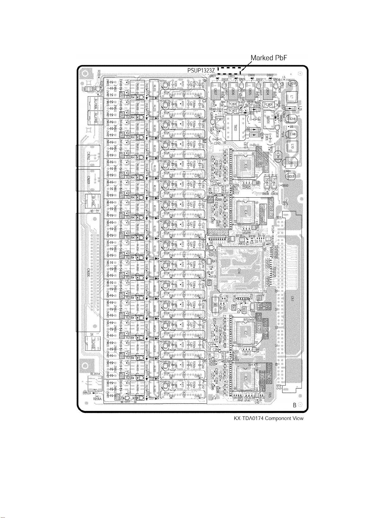
This model, and others like it, manufacturedusing leadfree solderwill have PbF stampedon
the PCB. Forservice and repairwork we suggest using the same type of solderalthough, with
some precautions, standardPbsoldercanalsobe used.
Caution
-PbF solder has amelting point that is50° ~ 70° F, (30° ~ 40°C)
higher than Pb solder. Please use asoldering iron with
temperature control and adjust itto 700° ± 20° F, (370° ± 10°C). In
case of using high temperature soldering iron, please be careful
not to heat too long.
-PbF solder will tend to splash ifitisheated much higher than its
melting point, approximately1100°F, (600°C).
-Ifyou must use Pb solder on aPCB manufactured using PbF
solder, remove as much of the original PbF solder as possibleand
be sure that anyremaining ismelted prior to applying the Pb
solder.
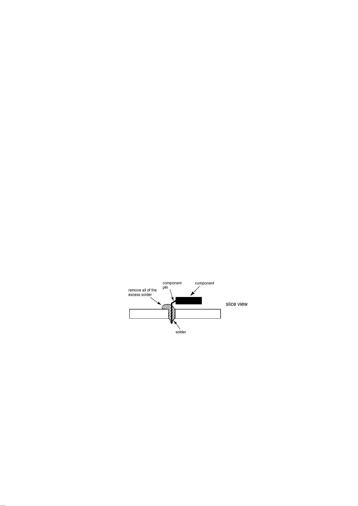
-When applying PbF solder to doublelayered boards, please check
the component side for excess which mayflow onto the opposite
side (See figure, below).
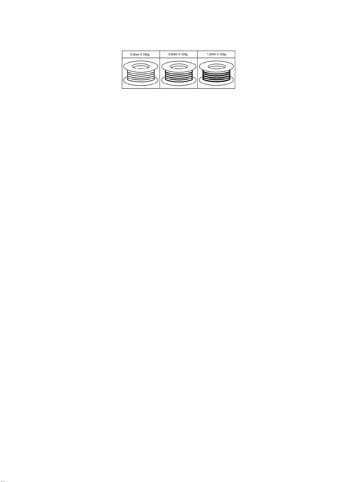
1.1. SUGGESTEDPbF SOLDER
There are several types of PbF solderavailable commercially. While this product is
manufacturedusing Tin, Silver, and Copper,(Sn+Ag+Cu), you canalsouse Tinand Copper, (Sn+
Cu), orTin, Zinc, and Bismuth, (Sn+Zn+Bi). Please check the manufacturer’s specific
instructions forthe melting points of theirproducts and anyprecautions forusing theirproduct
withothermaterials. The following leadfree (PbF) solderwire gauge are recommendedfor
service of this product: 0.3mm, 0.6mm and 1.0mm.
2

1.2. HOWTO RECOGNIZE THATPb FREE SOLDERISUSED
“PbF” is markedon the PCB toshowthat Pbfree solderis used.(See the figure below.)
3

2. FOR SERVICE TECHNICIANS
ICs and LSIs are vulnerable tostatic electricity.
Whenrepairing, the following precautions will helpprevent recurring malfunctions.
4

1. Cover the plasticparts boxes with aluminum foil.
2. Ground the soldering irons.
3. Use aconductive mat on the worktable.
4. Donot touch ICor LSI pins with bare fingers.
3. GENERAL DESCRIPTION
KX-TDA0174 (SLC16) is mountedintoa free slot of TDA100/200 system. Upto16 SLT canbe
randomlyconnectedbyusing SLC16 card. It does not have LPR onboard, and it is controlled
completelybyMPR.
4. SPECIFICATION
Functional Block Functional contents
Extension Interface Numberof Ports 8 ports
SLT Interface +30V 30mA Feeding function
Dial-pulse signal detecting function
DTMFsignal detecting function
Bell signal issuing function
Hook detecting function
Ringtripdetecting function
2W/4W converting function
Surge protective function
Infineon-manufactured4chcodec function
CODEC function
/A Iawswitching function
Test function (Loop back, Tone generation)
Programmable digital filtering function
Serial interface function
PIO function
DTMFReceiver 16 lines foreachport
Extension CallerID Onlyconnectorterminal is installed
On-boardRinger 20/25Hz 75Vrms
Phase control (Three-phase / Four-phase)
On-boardDC/DC Power
Supply Input +15V
Output +15V, +5V, +3.3V
Input +40V
Output forBell ringing relay: +160V, -100V
PowerFailure Forwarding
Function 4 lines supported
5

Functional Block Functional contents
Self-Diagnostic Function Carriedout withoutsire-line interface ina pair(onlyone port)
Speechpathtest, Dial pulse test, DTMFtest
ASIC EC bus interface function
CTbus interface function
Local bus interface function
Time switchfunction, Gaincontrolling function
Intelligent PIO function
LED DisplayCircuit Cardstatus indicating LED: Twocolors (Red/Green)
External Interface
Connector Extension
interface 50pinAmphenol connector: 1
Powerfailure
forwarding 4pinmodularjack: 2
5. NAMES AND LOCATIONS
Overview
Inside View
Note:
*Null slot is not available foranyoptional service cards.
5.1. INSTALLING/REMOVING THEOPTIONALSERVICECARDS
Slot Condition
6

CardType Slot Type
KX-TDA100: Free Slots 1 to5
KX-TDA200: Free Slots 1 to10 Option Slot MPR Slot
MPR Card No No Yes
CO Line Cards Yes No No
Extension Cards Yes No No
OPB3 Card Yes Yes No
CTI-LINK Card Yes Yes No
Caution:
To protect the back board from staticelectricity, do not touch parts
on the back board inthe mainunitand on the optional service
cards.To discharge static, touch ground or wear an earthing strap.
SLC16 Card
Function
16-port extension cardforSLT with4 powerfailure transferports.
Notes
-To connect the amphenol connector, refer to "Fastening Amphenol
Type Connector".
-For detailsabout power failure transfer, refer to "Auxiary
Connection for Power Failure Transfer".
Accessoryand User-suppliedltems
Accessory: screws x 2
7

User-supplied: amphenol connector
PinAssignments
Amphenol Connector
No. Signal Name Function No. Signal Name Function
1RA Ring port 1 26 TA Tipport 1
2 RB Ring port 2 27 TB Tipport 2
3 RC Ring port 3 28 TC Tipport 3
4 RD Ring port 4 29 TD Tipport 4
5 RE Ring port 5 30 TE Tipport 5
6 RF Ring port 6 31 TF Tipport 6
7 RG Ring port 7 32 TG Tipport 7
8 RH Ring port 8 33 TH Tipport 8
9 RI Ring port 9 34 TI Tipport 9
10 RJ Ring port 10 35 TJ Tipport 10
11 RK Ring port 11 36 TK Tipport 11
12 RL Ring port 12 37 TL Tipport 12
13 RM Ring port 13 38 TM Tipport 13
14 RN Ring port 14 39 TN Tipport 14
15 RO Ring port 15 40 TO Tipport 15
16 RP Ring port 16 41 TP Tipport 16
17-25 Reserved - 42-50 Reserved -
LED Indications
Indication Color Description
CARD STATUS Green/Red OFF: PowerOff
GreenON: Normal (all ports are idle)
GreenFlash(60 times perminute ): Normal (a port is inuse)
RedON: Fault (includes reset)
RedFlash(60 times perminute): Out of Service
Fastening Amphenol Type Connector
Anamphenol 57JE type connectoris usedon some of the optional sevice cards.
To connect anamphenol connector, use the spring latchorscrewtofix the upperpart and use
8

Velcro tape tofix the lowerpart of the connector.
AuxiliaryConnection forPowerFailure Transfer
Whenthe powersupplytothe HybridIP-PBX fails, powerfailure transfer(PFT) switches the
current connection tothe AuxiliaryConnection automatically. A specific SLT (determinedby
SystemProgramming) will be connectedtoselectedCO lines inthe event of systempower
failure. AuxiliaryConnection is requiredtoimplement this feature.
Connection
The following CO line and extension cards canbe usedforAuxiliaryConnections:
-Analog CO line cards: LCOT16 (4 PFT ports), and LCOT8 (2 PFT
port)
-Extension cards: MSLC16 (4 PFT ports), SLC16 (4PFT ports),
DHLC8(2 PFT port) and SLC8(2 PFT port)
9

Note
Pinassignments forports 3 and 4 are the same as those of ports 1 and 2.
Accessoryand User-suppliedltems
Accessory: none
User-supplied: RJ11 connectors
RJ11 ConnectorPinAssignments forCO line Crad
No.Signal Name Function
1R2 Ring port 2
2 R1 Ring port 1
3T1 Tipport 1
4T2 Tipport 2
RJ11 ConnectorPinAssignments forExtension Card
No.Signal Name Function
1 T2 Tipport 2
2T1 Tipport 1
3 R1 Ring port 1
4 R2 Ring port 2
Installing Optional Service Cards
10

1. Insert the card along the guide rails.
2. Holding the card as follows, push the release lever inthe direction
of the arrow so that the card ismade to engage with the
connector on the back board securely.
3. Turn the 2screwsclockwise to fixthe card.
11

6. TROUBLESHOOTING GUIDE
12

13

14

15

16

17

18

7. BLOCK DIAGRAM
8. CIRCUIT OPERATION
8.1. IC14(ASIC)
-ECbus interface
Independent bus for 16bit/8MHztwo-wayaddress data multiplex.
-CTbus interface
Supports eight 8.192MHzhighways(128 time slots).
-Local TSW
Exchanges the time slots between CTbus (1024ch) and local
highway(64ch).
-Local highwayInterface
Holds 2.048, 4.096, 8.192MHzhighway(Upto 64 time slots) (VOX
bus onboard)Astream 0through 15 (1 stream = 128 time slots) of
PCMdata can be switched to alocal highway(64time slots). See
the figure blow for the examples of the local highwaytime slot
configurations (You can assign desired slots.).
19

-Local gaincontrol
Controlsthe gainof the local highwayup-and-down64ch in1db
step arbitrarily.
-CODECinterface
Can connect up to four Infineon-manufactured PEB2466, and is
intended for enabling the line control.
-GPIO interface
Parallel interface that isarbitrarilyand bidirectionally
programmable.
8.2. RESET CIRCUIT
Whenstarting the system, the ASIC reset cancel will be executedbyMPR through EC_nRST.
-LEDstatus indicator LED(2 colors)
Red ON:Fault(Including RESET)
Green ON:INS(Line not inuse)
Green Flash (60/m): INS(Line inuse)
Red Flash: OUS
OFF: Power supplymalfunction
8.3. CODECFUNCTION(IC201,202,250,251)
Infineon PEB2466 CODEC is installed. The analogue features suchas BN, frequency
20
Table of contents
Other Panasonic PCI Card manuals