manuals.online logo
Brands
  1. Home
  2. •
  3. Brands
  4. •
  5. Panasonic
  6. •
  7. Receiver
  8. •
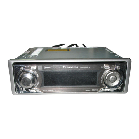
  9. Panasonic CQ-RDP153N User manual

Panasonic CQ-RDP153N User manual

ORDERNo. ACED030237C8
AUTOMOTIVE AFTERMARKET
CQ-RDP153N / CQ-RDP143N / CQ-RDP133N / CQ-RDP123N /
CQ-RDP113N / CQ-RDP103N / CQ-RDP003N
RemovableFront Panel CD Player / Receiver with CD Changer
Control
SPECIFICATIONS
Specifications*
1
General
Power Supply DC 12V (11V - 16V),
Test Voltage14.4V
NegativeGround
ToneControls Bass ; ±12dB at 100Hz
Treble; ±12dB at 10kHz
Current Consumption Less than2.5A(CD mode, 0.5W×
4ch)
MaximumPower Output 45W×4ch(at 4 )
Speaker Impedance 4-8
Pre-AmpOutput Voltage 2.5V (CD mode)
Pre-AmpOutput Impedance 200
FM StereoRadio
FrequencyRange 87.5- 108MHz
UsableSensitivity 6dB/ V (S/N 30dB)
MWRadio
FrequencyRange 531 - 1,602kHz
UsableSensitivity 28dB/ V (S/N 20dB)
LW Radio
FrequencyRange 153 - 279kHz
UsableSensitivity 32dB/ V (S/N 20dB)
CD Player
Sampling Frequency 8 times oversampling
Pick-UpType Astigma 3-beam
Light Source SemiconductorLaser
Wavelength 780nm
FrequencyResponse 20Hz to20,000Hz (±1dB)
Signal toNoise Ratio 96dB
Channel Separation 75dB
Dimensions** 178(W)×50(H)×155(D)mm
Weight** 1.4kg
*Specificationsand thedesign are subject topossible
modification without notice duetoimprovements.
** Dimensionsand Weight shownare approximate.
2003 Matsushita ElectricIndustrial Co., Ltd. All rights reserved.
Unauthorized copying and distribution isaviolation of law.
2
1. ABOUT LEAD FREE SOLDER (PbF)
Distinction of PbF PCB:
PCBs (manufactured) using leadfree solderwill have a PbF stampon the PCB.
Caution :
-Pb free solder has ahigher melting point than standard solder;
Typicallythe melting point is50 -70°F (30 -40°C)higher. Please
use asoldering iron with temperature control and adjust itto 700 ±
20°F (370 ± 10°C). Incase of using high temperature soldering
iron, please be careful not to heat too long.
-Pb free solder will tend to splash when heated too high (about
1100°F/600°C)
-Thislead free solder will be used for the products after serial No.
1,000,001.
2. FEATUERS
-PLL (Phase Locked Loop) synthesized tuning.
-18-FM, 6-AMpresets with preset scan
-Digital servo for reliableCD playback.
-Removableface plate.
-RDS(RadioData System) function.
3. LASER PRODUCTS
3
4. FUSE
Use fuses of the same specifiedrating (15A). Using different substitutes orfuses withhigher
ratings, orconnecting the unit directlywithout a fuse, couldcause fire ordamage tothe unit.
5. MAINTENANCE
Wipe the unit witha soft drycloth. / Neverapplyvolatile liquids suchas benzine and thinnerto
prevent damage
6. NOTES
[RADIO BLOCK]
Donot align the AM/FM package block. Whenthe package block is necessary, it will be supplied
alreadyalignedat the factory.
[CD DECK BLOCK]
This model has no servoalignment points because microcomputercontrols the servocircuit.
[OTHER]
The following table describes the differences between7 models.
Changer Control Pre-OUT Illumination Color Face Color
CQ-RDP153N Yes 4(Front/Rear) Blue/Red Plating Silver
CQ-RDP143N Yes 4(Front/Rear) Amber Plating Silver
CQ-RDP133N Yes 4(Front/Rear) Green Plating Silver
CQ-RDP123N None 2(Rear) Blue/Red Coating Black
CQ-RDP113N None 2(Rear) Amber Coating Black
CQ-RDP103N None 2(Rear) Green Coating Black
CQ-RDP003N None 2(Rear) Amber Coating Silver
4
7. DIMENSIONS
8. WIRING CONNECTION
5
9. BLOCK DIAGRAM
6
10. TERMINALS DESCRIPTION
7
10.1. MainBlock
IC601 : C2CBHF000281
Pin No. Port Descriptions I/O(V) FM(V) AM(V) CD (V)
1NC (Connecting to ground) - 0 0 0
2 NC (Connecting to ground) - 0 0 0
3 NC (Connecting to ground) - 0 0 0
4AVSS Analog ground - 0 0 0
5AF MUTE AF mute O 5.1 5.1 5.2
6AMP-CNT Power Amp. stand-by O 5.1 5.1 5.2
7AVREF Reference voltage - 5.1 5.1 5.2
8 CD-SO CD data I 0 0 0
9CD-SI CD data O 0 0 2.4
10 CD-SCK CD clock O 0 0 5.1
11 CD.C DATA CD CH data I 0 0 0
12 BATT Batterylevel detection I 5.1 5.1 5.1
13 CD.C CLK CD.CH clock I 0 0 0
14 REMOUT CD.CH remote O 5.1 5.1 5.1
15 BZOUT Buzzer out O 0 0 0
16 PLL-DO Data from PLL I 5.1 5.1 5.1
17 PLL-DI Data for PLL O 0 0 0
18 PLL-CLK Clock for PLL O 5.1 5.1 5.2
19 PLL-CE PLL chip enable O 0 0 0
20 NC No connection - - - -
21 NC No connection - - - -
22 MUTE Mute control O 5.1 5.1 5.1
23 NC No connection - - - -
24 CD-STB CD strobe O 0 0 5.1
25 CD-A0 CD address 0 O 0 0 4.4
26 CD-RST CD reset O 0 0 5.1
27 CD-RFOK CD RFOK signal I 0 0 5.0
28 CD-LOCK CD lock signal I 0 0 5.0
29 CD-LIMIT CD limitsw I 0 0 5.1
30 CD-SW2 CD SW2 I 5.1 5.1 0
31 NC No connection - - - -
32 NC No connection - - - -
33 Vss1 Ground - 0 0 0
34 NC No connection - - - -
35 ST FMstereo detection I 5.0 5.1 0
36 IC2-CLK Electronicvolumeclock O 5.1 5.1 5.2
37 IC2-DATA Electronicvolumedata I/O 5.1 5.1 5.2
38 S.LED Notused - - - -
39 NC No connection - - - -
40 NC No connection - - - -
41 LCD-DI LCD data output O 0 0 0
42 LCD-DO LCD data input I 5.0 5.0 5.0
43 LCD-CLK LCD clock O 0 0 0
44 LCD-CE LCD chip enableoutput O 0 0 0
45 POWER LED Pilotlamp on O 0 0 0
46 ANT.CONT Notused - - - -
47 NC No connection - - - -
48 NC No connection - - - -
49 REM-IN_SUB Remote control sig. sampling I 4.4 4.4 4.4
50 NC No connection - - - -
8
Pin No. Port Descriptions I/O(V) FM(V) AM(V) CD (V)
51 NC No connection - - - -
52 NC No connection - - - -
53 NC No connection - - - -
54 TEL-MUTE Telephonemute I 5.1 5.1 5.1
55 PANEL Panel detect I 4.8 4.8 4.9
56 CD-CNT CD power control O 0 0 5.1
57 PWR CNT Power control O 5.0 5.0 5.0
58 NC No connection - - - -
59 RDSDATA RDSdata I 2.5 2.5 2.5
60 /RESET Reset input I 5.1 5.1 5.1
61 REM-DATA Remocon data input I 4.4 4.4 4.4
62 CD_SW1 CD modeSW I 0 0 0
63 RDSCLK RDSclock I 2.5 2.5 2.5
64 CD.C.STB CD.CH strobe I 0 0 0
65 ROTALY.1 Volumeup SW I 5.1 5.1 5.1
66 ROTALY.2 Volumedown SW I 0 0 0
67 VSS0 Ground - 0 0 0
68 VDD1 +5Vpower supply - 5.1 5.1 5.1
69 X2 Crystal oscillator - 3.1 3.1 3.1
70 X1 Crystal oscillator - 2.2 2.2 2.2
71 Vpp (Ground pull-down) - 0 0 0
72 XT2 Crystal oscillator - 3.1 3.1 3.1
73 XT1 Crystal oscillator - 2.5 2.5 2.5
74 VDD0 +5Vpower supply - 5.1 5.1 5.1
75 AVREF Analog reference voltage - 5.1 5.1 5.1
76 VSM S-meter detection I 0 0 0
77 ACC ACC level detection I 5.1 5.1 5.1
78 INITA Initial value(Note 2) I #1 #1 #1
79 NC No connection - - - -
80 NC No connection - - - -
Note 1 :
Voltage measuerments are with respect to ground, with avoltmeter
(internal resistance :10M ohms).
Note 2 : #1
0V :CQ-RDP153/143/133N
5.1V :CQ-RDP123/113/103/003N
10.2. DisplayBlock
IC901 : YEAMLC75854T
9
Pin No. Port Descriptions I/O(V) (V)
1-8 SEG1-8 LCD segment O 2.5
9-35 SEG9-35 LCD segment O 2.5
36-39 NC No connection - -
40-43 COM1-4 LCD common O 2.5
44 NC No connection - -
45-49 KS2-6 Keydata output O 0.9
50-54 KI1-5 Keydata input I 0
55 TEST (Connecting to ground) - 0
56 VDD +5Vpower supply - 5.1
57 VDD1 Ground through capacitor - 3.3
58 VDD2 Ground through capacitor - 1.7
59 Vss Ground - 0
60 OSC CR oscillator - 3.9
61 DO Keydata output O 4.4
62 CE Chip enable I 0
63 CLK LCD clock I 0
64 DI LCD data input I 0
10.3. CD Servo Block
IC101 : C1BB00000665
Pin No. Port Descriptions I/O Vol.(V)
1D.GND Digital logicGround - 0
2 RFOK RFOK outputsignal O 5.0
3 /RST System reset I 5.1
4A0 Command/Parameter specification I 4.5
5 /STB Serial data strobe I 5.1
6 /SCK Data shift clock I 5.1
7SO Serial data O 0
8SI Serial data I 2.4
9XTALEN (Connecting to ground) - 0
10 D.VDD Digital logicpower supply - 5.0
11 DA.VDD DAC power supply - 4.8
12 R_OUT Audio R ch O 2.4
13 DA.GND DAC ground - 0
14 REGC Bypass capacitor for SCF regurator - 2.5
15 DA.GND DAC ground - 0
16 L_OUT Audio L ch O 2.4
17 DA.VDD DAC power supply - 4.8
18 R+ Notused - -
19 R- Notused - -
20 L- Notused - -
21 L+ Notused - -
22 X.VDD Crystal OSC power supply - 5.0
23 /XTAL Crystal OSC terminal - 2.4
24 XTAL Crystal OSC terminal - 2.2
25 X.GND Crystal OSC ground - 0
26 D.VDD Digital logicpower supply - 5.0
27 EMPH Notused - -
28 FLAG Notused - -
29 DIN DAC serial data I 2.6
30 DOUT DAC serial data O 2.6
31 SCKIN DAC shift clock I 2.7
10
Pin No. Port Descriptions I/O Vol.(V)
32 SCKO DAC shift clock O 2.7
33 LRCKIN DAC LRCK signal I 2.5
34 LRCK DAC LRCK signal O 2.5
35 HOLD/WDCK Notused - -
36 TX Notused - -
37 D.GND Digital logicGround - 0
38 C16M Notused - -
39 LIMIT (Connecting to VDD) - 5.0
40 D.VDD (Connecting to VDD) - 5.0
41 LOCK EFMSYNC detection O 5.0
42 RFCK Notused - -
43 MIRR/WFCK Notused - -
44 PLCK Notused - -
45 D.GND Digital logicGround - 0
46 C1D1 Notused - -
47 C1D2 Notused - -
48 C2D1 Notused - -
49 C2D2 Notused - -
50 C2D3 Notused - -
51 D.VDD Digital logicpower supply - 5.0
52 PACK Notused - -
53 TSO Notused - -
54 TSI (Connecting to ground) - 0
55 /TSCK (Connecting to ground) - 0
56 TSTB (Connecting to ground) - 0
57 D.GND Digital logicGround - 0
58 TEST0 (Connecting to ground) - 0
59 TEST1 (Connecting to ground) - 0
60 ATEST Notused - 2.1
61 A.GND Analog logicGround - 0
62 FD Focusdrive O 2.6
63 TD Traking drive O 2.5
64 SD Sled drive O 2.5
65 MD Spindledrive O 2.6
66 DAC0 Notused - -
67 DAC1 Notused - -
68 DAC2 Notused - -
69 DAC3 Notused - -
70 A.VDD Analog logicpower supply - 5.0
71 EFM EFMsignal O 2.7
72 ASY Reference voltagefor EFMcomp. I 2.5
73 C3T Capacitor terminal for 3Tdetection - 2.7
74 RFI RF for EFMdata generation I 2.5
75 AGCO RF signal output(after gain adjustment) O 2.5
76 AGCI RF-AGC amp input I 2.5
77 RFO RF summing amp output O 2.8
78 EQ2 C/R terminal for RF amp equalizer - 2.6
79 EQ1 C/R terminal for RF amp equalizer - 0.5
80 RF- RF summing amp inverted input I 2.4
81 A.GND Analog logicGround - 0
82 A Photo detector Ainput I 2.7
83 C Notused - -
84 B Photo detector B input I 2.7
85 D Notused - -
11
Pin No. Port Descriptions I/O Vol.(V)
86 F Photo detector F input I 3.0
87 E Photo detector Einput I 3.0
88 A.VDD Analog logicpower supply - 5.0
89 REFOUT Reference voltageoutput O 2.5
90 FE- Focuserror amp input I 2.5
91 FE0 Focuserror amp output O 2.5
92 TE- Tracking error amp input I 2.5
93 TE0 Tracking error amp output O 2.5
94 TE2 Tracking error amp output O 2.6
95 TEC Tracking comparator input I 2.5
96 A.GND Analog logicGround - 0
97 PD PD detection I 0
98 LD LD control O 3.6
99 PN (Connecting to ground) - 0
100 A.VDD Analog logicpower supply - 5.0
11. PACKAGE AND IC BLOCK DIAGRAM
11.1. MainBlock PA51 : C5BA00000110
12
13
14
IC201 : C1BB00000543
15
IC901 : YEAMDA7479D
IC271 : C1EA00000026
16
IC650 : YEAMC14584BE
IC701 : C0EBG0000038
IC703 : C0CAAYG00005
17
IC401 : C1BB00000644
11.2. DisplayBlock IC902 : PNA4602M01MC
11.3. CD Servo Block IC301 : C0GBY0000020
18
12. REPLACEMENT PARTS LIST
Notes :
1. Besure to make your orders of replacement parts according to
thislist.
2. Important safetynotice: Components, identified bymark have
special characteristics important for safety. When replacing any
of these components, use onlymanufacturer's specified parts.
19
3. Location keysinthe remarks column indicates the general
location of the parts showninthe exploded drawing, as inaroad
map.
4. The marking (RTL) indicates that Retention Time islimited for this
item. After the discontinuation of assemblyinproduction, the item
will continue to be availablefor aspecificperiod of time. The
retention period of availabilityisdependent on the type of
assembly, and inaccordance with the lawsgoverning part and
product retention. After the end of thisperiod, the assemblywill
no longer be available.
-Order intake period isbasicallysixmonths after the first
shipment.
5. "A", "B", “C”, “D”, “E”, “F” and “G”marks inremarks column are
indicated as follows:
-A:CQ-RDP153N
-B:CQ-RDP143N
-C:CQ-RDP133N
-D:CQ-RDP123N
-E:CQ-RDP113N
-F:CQ-RDP103N
-G :CQ-RDP003N
20

This manual suits for next models

6

Other Panasonic Receiver manuals

Panasonic SA-XR57E User manual

Panasonic

Panasonic SA-XR57E User manual

Panasonic KX-THA14 User manual

Panasonic

Panasonic KX-THA14 User manual

Panasonic CQ-D1703N User manual

Panasonic

Panasonic CQ-D1703N User manual

Panasonic CQ-VD5505W User manual

Panasonic

Panasonic CQ-VD5505W User manual

Panasonic SAXR25 - DIGITAL A/V RECEIVER User manual

Panasonic

Panasonic SAXR25 - DIGITAL A/V RECEIVER User manual

Panasonic RF-ND277R User manual

Panasonic

Panasonic RF-ND277R User manual

Panasonic WVRC100 - BROADCAST RECEIVER Operating instructions

Panasonic

Panasonic WVRC100 - BROADCAST RECEIVER Operating instructions

Panasonic SA-XR15 User manual

Panasonic

Panasonic SA-XR15 User manual

Panasonic SiriusXM CQ-RXBT490U User manual

Panasonic

Panasonic SiriusXM CQ-RXBT490U User manual

Panasonic CQVW100U - Car Audio - In-Dash DVD Receiver User manual

Panasonic

Panasonic CQVW100U - Car Audio - In-Dash DVD Receiver User manual

Panasonic RF-P150D User manual

Panasonic

Panasonic RF-P150D User manual

Panasonic SAHE70 - RECEIVER User manual

Panasonic

Panasonic SAHE70 - RECEIVER User manual

Panasonic RF-SW50 User manual

Panasonic

Panasonic RF-SW50 User manual

Panasonic LUMIX DMW-XLR1E User manual

Panasonic

Panasonic LUMIX DMW-XLR1E User manual

Panasonic CS-HZ25UKE User manual

Panasonic

Panasonic CS-HZ25UKE User manual

Panasonic SAHE100 - RECEIVER User manual

Panasonic

Panasonic SAHE100 - RECEIVER User manual

Panasonic CQ-VD5505W User manual

Panasonic

Panasonic CQ-VD5505W User manual

Panasonic SH-FX50T User manual

Panasonic

Panasonic SH-FX50T User manual
Panasonic TUIRD10 - DSS RECEIVER User manual

Panasonic

Panasonic TUIRD10 - DSS RECEIVER User manual

Panasonic HDMI SA-XR700 User manual

Panasonic

Panasonic HDMI SA-XR700 User manual

Panasonic SA-XR50S User manual

Panasonic

Panasonic SA-XR50S User manual

Panasonic SAHE9 - RECEIVER User manual

Panasonic

Panasonic SAHE9 - RECEIVER User manual

Panasonic WVRC150 - CONTROLLER User manual
Panasonic

Panasonic WVRC150 - CONTROLLER User manual

Panasonic K-SRC14 User manual

Panasonic

Panasonic K-SRC14 User manual
Popular Receiver manuals by other brands

FreeFlight 87099 Series installation manual

FreeFlight

FreeFlight 87099 Series installation manual

Sony XT-500DTV User's installation and operation manual

Sony

Sony XT-500DTV User's installation and operation manual

volkano VK-8000-BK instruction manual

volkano

volkano VK-8000-BK instruction manual

Rotel RSX-1057 Command list

Rotel

Rotel RSX-1057 Command list

AMG AMG4704E-SF instruction manual

AMG

AMG AMG4704E-SF instruction manual

DELTA DORE AC 51115 quick start guide

DELTA DORE

DELTA DORE AC 51115 quick start guide

Kramer C-A35M/IRR-03 installation instructions

Kramer

Kramer C-A35M/IRR-03 installation instructions

GRT Avionics ADS-B Installation and user manual

GRT Avionics

GRT Avionics ADS-B Installation and user manual

Onkyo TX-DS474 Service manual

Onkyo

Onkyo TX-DS474 Service manual

mcmurdo NAV6 user manual

mcmurdo

mcmurdo NAV6 user manual

Saorview DXD7025SVC quick start guide

Saorview

Saorview DXD7025SVC quick start guide

Megasat HD 900 Twin CI+ user manual

Megasat

Megasat HD 900 Twin CI+ user manual

Alpine INE-W611D installation manual

Alpine

Alpine INE-W611D installation manual

Audiovox GMRS-2000 instruction manual

Audiovox

Audiovox GMRS-2000 instruction manual

FONESTAR MSHRM-1200L quick start guide

FONESTAR

FONESTAR MSHRM-1200L quick start guide

SABINE SWM7000 - quick guide

SABINE

SABINE SWM7000 - quick guide

Onkyo TX-L55 instruction manual

Onkyo

Onkyo TX-L55 instruction manual

LG ARX5000 owner's manual

LG

LG ARX5000 owner's manual

manuals.online logo
manuals.online logoBrands
  • About & Mission
  • Contact us
  • Privacy Policy
  • Terms and Conditions

Copyright 2025 Manuals.Online. All Rights Reserved.