Left
Reel
Table
Brake
Rod(1)
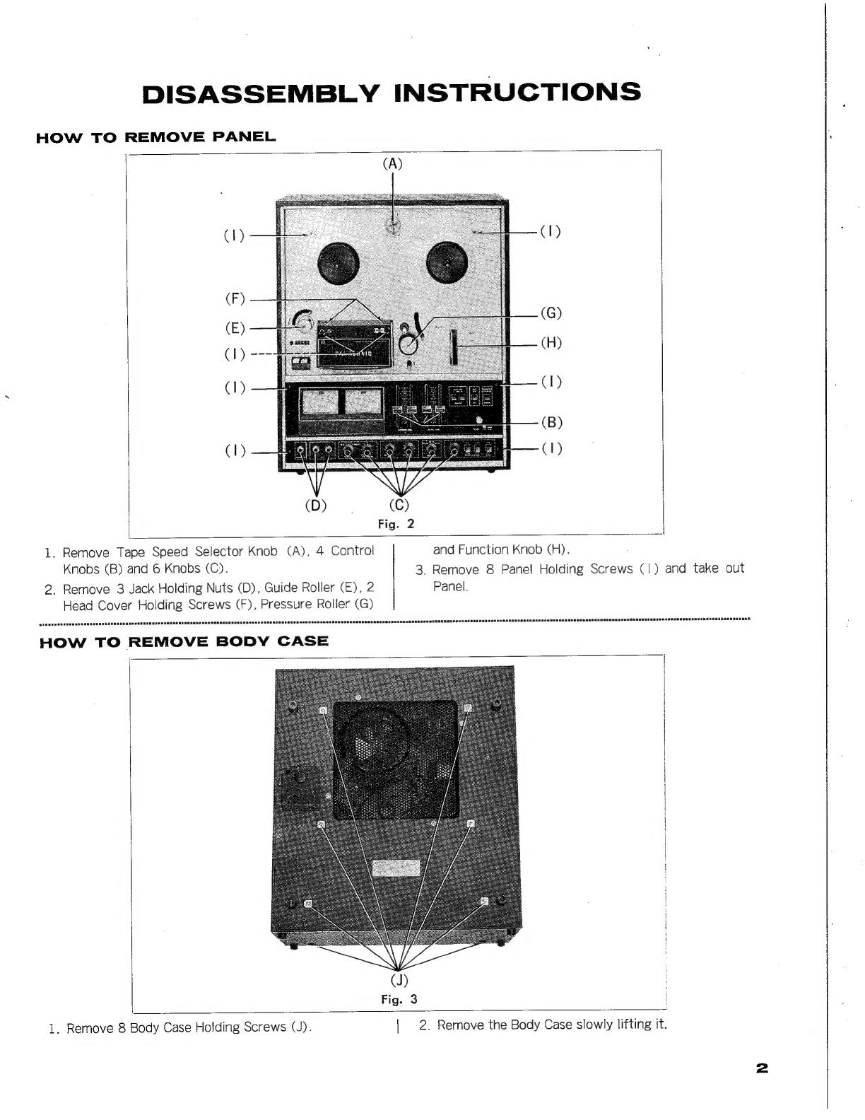
Fig.
10
Right
Reel
Table
Pulley(1)
Adjusting
Method:
Make
the
adjustment
by
use
of
elongation
and
contrac-
tion
of
the
Right
and
Left
Brake
Springs.
(Fig.
10)
Brake
Timing:
During
FF
or
PLAY
mode,
brake
should
be
SA
een
ee
a
nee
deen
nme
RGRER
AREA
SORA
RERR
Re
nRHER
AHR
ARN
ON
RON
SRETORNOR
ESE
REN
ARR
ead
eon
Ree
ERRE
NORE
ROSRHOEReEsREAeedEenensonnen:
applied
earlier
on
the
Supply
Ree!
side
than
the
Takeup
Ree!
side.
The
reverse
applies
during
the
REW
or
REVERSE
mode.
non
RonaDa
SE
seRnnenuenennsessenneensasuaunnnESennnennaaesansnaennnnnenenn
eke
nODRGRRGESRRARHAHREOEESEMERMAnannnenneanons
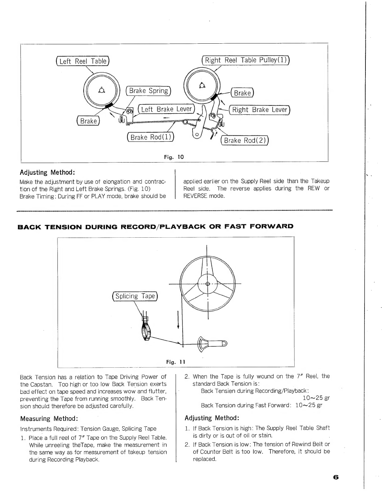
BACK
TENSION
DURING
RECORD/PLAYBACK
OR
FAST
FORWARD
Back
Tension
has
a
relation
to
Tape
Driving
Power
of
the
Capstan.
Too
high
or
too
low
Back
Tension
exerts
bad
effect
on
tape
speed
and
increases
wow
and
flutter,
preventing
the
Tape
from
running
smoothly.
Back
Ten-
sion
should
therefore
be
adjusted
carefully.
Measuring
Method:
Instruments
Required:
Tension
Gauge,
Splicing
Tape
1.
Place
a
full
reel
of
7”
Tape
on
the
Supply
Reel
Table.
While
unreeling
theTape,
make
the
measurement
in
the
same
way
as
for
measurement
of
takeup
tension
during
Recording
Playback.
2.
When
the
Tape
is
fully
wound
on
the
7”
Reel,
the
standard
Back
Tension
is:
Back
Tensien
during
Recording/Playback
:
10~25
ger
Back
Tension
during
Fast
Forward:
10~25
gr
Adjusting
Method:
1.
If
Back
Tension
is
high:
The
Supply
Reel
Table
Shaft
is
dirty
or
is
out
of
oil
or
stain.
2.
|f
Back
Tension
is
low:
The
tension
of
Rewind
Belt
or
of
Counter
Belt
is
too
low.
Therefore,
it
should
be
replaced.