P&B MPC2000+ User manual

MPC2000+ Technical Manual
ISSUE 7 28/9/99
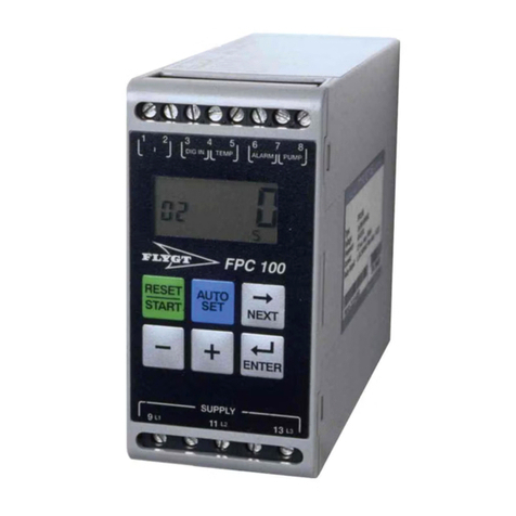
MPC2000+
Motor Protection Controller
P&B Engineering
Belle Vue Works
Boundary Street
Manchester
M12 5NG
Tel: 0161 230 6363
Fax:0161 230 6464

MPC2000+ Technical Manual
ISSUE 7 28/9/99
Contents
CONTENTS................................................................................................................................................................... 2
1. INTRODUCTION..................................................................................................................................................... 1
2. SUMMARY OF MPC2000+ FEATURES .............................................................................................................. 2
2.1. CONTROL FUNCTIONS ............................................................................................................................................... 2
2.2. PROTECTIVE FUNCTIONS ........................................................................................................................................... 2
2.3. DISPLAYED DATA...................................................................................................................................................... 2
2.4. FEATURES ................................................................................................................................................................. 3
3. TECHNICAL SPECIFICATION ............................................................................................................................ 3
3.1. AUXILIARY POWER SUPPLY....................................................................................................................................... 3
3.2 PHASE CURRENT INPUTS ............................................................................................................................................ 3
3.3. EARTH FAULT CURRENT INPUTS ............................................................................................................................... 4
3.4. LINE VOLTAGE INPUTS.............................................................................................................................................. 4
3.5. THERMISTOR/RTD INPUTS........................................................................................................................................ 4
3.6. OVERLOAD ALARM AND TRIP CURVES ..................................................................................................................... 4
3.7. CURRENT UNBALANCE ALARM AND TRIP ................................................................................................................. 4
3.8. FAULT TIME DELAYS ................................................................................................................................................ 5
3.9. RELAY CONTACTS..................................................................................................................................................... 5
3.10. DIELECTRIC STRENGTH ........................................................................................................................................... 5
3.11. AUTO RESTART CIRCUITRY..................................................................................................................................... 5
4. MPC2000+ SCHEMATIC DIAGRAMS................................................................................................................. 5
5. MPC2000+ MEASURED INPUTS.......................................................................................................................... 7
5.1. POWER SUPPLY (LIVE-4, NEUTRAL-5, EARTH-7) ...................................................................................................... 7
5.2. VT INPUTS (L1-16, L2-18, L3-20, N-17,19,21-IF USED) ........................................................................................... 7
5.3. CURRENT SENSOR INPUTS (10,11,12,13,14,15) ........................................................................................................ 7
5.4. EARTH FAULT CT INPUTS (8,9)................................................................................................................................. 7
5.5. TEMPERATURE INPUTS (23,24,25;26,27,28;29,30,31) .............................................................................................. 7
5.6. POWER. ..................................................................................................................................................................... 7
6. MPC2000+ CONTROL INPUTS/OUTPUTS......................................................................................................... 8
6.1. OUTPUT RELAYS ....................................................................................................................................................... 8
6.2. CONTROL INPUTS ...................................................................................................................................................... 8
6.2.1. Key Switch......................................................................................................................................................... 8
6.2.2. Emergency Stop................................................................................................................................................. 8
6.2.3. ESD 3 Relay ...................................................................................................................................................... 8
6.2.4. Start A and Start B Input Terminals (78,76) ..................................................................................................... 8
6.2.5. Aux. Live (55,58,61,65,68,71,74,77) ................................................................................................................. 8
6.2.6. Stop Input (79) .................................................................................................................................................. 8
6.2.7. Plant Interlock (75)........................................................................................................................................... 9
6.2.8. Local/Remote (73)............................................................................................................................................. 9
6.2.9. PLC/Serial Port (72) ......................................................................................................................................... 9
6.2.10. Authorise Key (70) .......................................................................................................................................... 9
6.2.11. PLC Reset (69) ................................................................................................................................................ 9
6.2.12. PLC Control A (67)......................................................................................................................................... 9
6.2.13. PLC Control B (66)......................................................................................................................................... 9
6.2.14. Serial Port (+ve = 3, -ve = 1, Shield = 2) ...................................................................................................... 9
6.2.15. Speed Switch (64)............................................................................................................................................ 9
6.2.16. Contactor A and B Status (62,63,59,60) ......................................................................................................... 9
6.2.17. Isolator (56,57) ............................................................................................................................................. 10
6.2.18. External Fault 2 (52)..................................................................................................................................... 10
6.2.19. External Test Position (53)............................................................................................................................ 10
6.2.20. External Fault 3 (53)..................................................................................................................................... 10

MPC2000+ Technical Manual
ISSUE 7 28/9/99
6.2.21. Emergency Stop (54) .....................................................................................................................................10
7. MPC2000+ FACEPLATE FUNCTIONS ..............................................................................................................11
7.1. LED STATUS PANEL ................................................................................................................................................11
8. MPC FUNCTIONAL KEYPAD & DISPLAY......................................................................................................12
LIQUID CRYSTAL DISPLAY..............................................................................................................................................12
9. MPC2000+ SETTING PAGES...............................................................................................................................15
9.1. MPC2000+ COMMUNICATION SETTINGS.................................................................................................................15
9.2. SYSTEM SETTINGS ...................................................................................................................................................15
9.3. VOLTAGE SETTINGS.................................................................................................................................................18
9.4. CURRENT SETTINGS.................................................................................................................................................18
9.5. TEMPERATURE SETTINGS ........................................................................................................................................22
9.6. TRIPPING/ALARM OPTIONS ......................................................................................................................................22
9.7. MPC2000+ DATA DISPLAY PAGES..........................................................................................................................25
9.8. MPC2000+ SETTING PAGES SUMMARY ..................................................................................................................26
9.9. MPC2000+ DATA PAGES SUMMARY.......................................................................................................................28
10. MPC2000+ COMMUNICATIONS......................................................................................................................29
11. MPC2000+ FLASH/CONSTANT MESSAGES.................................................................................................29
12. MPC2000+ INTERNAL TEST ROUTINES .......................................................................................................30
13. MPC2000+ FAULT FINDING .............................................................................................................................31
14. MPC2000+ THERMAL OVERLOAD PROTECTION.....................................................................................32
15. MPC2000+ INSTALLATION ..............................................................................................................................36
15.1. CASING ..................................................................................................................................................................36
15.2 MPC2000+ TERMINATIONS....................................................................................................................................37
16. STARTING METHODS. ......................................................................................................................................41
16.1 DIRECT ON LINE.....................................................................................................................................................41
16.2 STAR/DELTA...........................................................................................................................................................41
16.3 REVERSING.............................................................................................................................................................41
16.4. TWO SPEED. ..........................................................................................................................................................41
16.5. CIRCUIT BREAKER. ................................................................................................................................................41
17. FAST SCAN ANALOGUE DATA .......................................................................................................................42
18. CHANGES TO THE MANUAL...........................................................................................................................42


MPC2000+ Technical Manual
P&B Engineering ISSUE 7 28/9/99 Page 1
1. Introduction
The MPC2000+ Goldstart Motor Protection Controller is a highly sophisticated microprocessor based motor
protection and control unit, specifically designed to be used on motors with full load currents upto 2000 Amps, at any
voltage and as an integral part of any type or manufacture of Motor Control Centre. All of the latest features are
included in the MPC2000+ to allow total control, protection and monitoring of motor starters either by direct hard
wire inputs or via the RS485 serial port.
The MPC2000+ can be used to control Direct on Line, Star-Delta, Reversing and Two Speed motor starters and by
the use of RMS current sampling, enables the MPC2000+ to be used in conjunction with A.C. Variable speed drives
or Soft Starters, without any affect on the protection performance . The control of circuit breakers can also be
accomplished using the MPC2000+.
The MPC2000+ monitors current, voltage and temperature inputs to provide the most comprehensive motor
protection package ever produced by P & B Engineering. This combined with all the necessary control and
monitoring functions and a high speed communications facility all within a small easily installed package at a cost
which is less than previously charged for a sophisticated microprocessor motor protection relay, make the
MPC2000+ the most attractive Motor Protection and Control device available today.
All hard wired control inputs are connected to, the MPC2000+ via optically isolated inputs to enable all starting,
stopping and tripping commands to be carried out by the MPC2000+. Status of all individual hard wired contacts is
also provided both locally via the liquid crystal display and remotely via the RS485 communications port.
All MPC2000+ setting parameters are programmed independently for each unit via the integral keypad and liquid
crystal display on the front plate or via the RS485 communications port and the IBM PC based MPCSET software
package available with the MPC2000+.
During operational conditions the LCD also gives access to accurate running, statistical and fault data such as; Phase
Volts, Phase Amps, thermal capacity, Time to Trip, Phase unbalance, Motor hours run, number of starts and many
more.
Light Emitting Diodes mounted on the front plate give visual indication of the motor status such as Motor Running,
Motor Stopped, Alarm or Trip conditions etc.
Flexible high speed control via PLC or DCS systems is obtained through the MPC2000+'s RS485 communications
port, allowing computer access to full control and monitoring of motor data, including : running data, motor statistical
data and control input status.
All MPC2000+ protective functions can be individually configured to enable or disable tripping and alarm functions,
enabling protection to be simplified for the very lowest motor ratings. In addition each protective function can be set
to allow self or manual reset after alarm or trip and manual reset can be set to allow resets after an alarm or trip to be
made locally, remotely or by authorised personnel only.
A unique 'Protection Only' mode enables the MPC2000+ to be installed for protection only purposes, this requires
only conventional current transformer and trip output wiring, enabling simple installation into existing equipment with
minimum wiring modifications. This allows users to take full advantage of the enhanced protective capability and the
RS485 communication facilities provided by the MPC2000+.

MPC2000+ Technical Manual
Page 2 ISSUE 7 28/9/99
2. Summary of MPC2000+ Features
2.1. Control Functions
Full Control of:
Direct on Line Motor Starters
Direct on line Reversing Motor Starters
Direct on Line 2 Speed Motor Starters
Star/Delta Motor Starters
Undervoltage Dip Restart Facility
Motor Starts Limitation
Integral Start & Stayput Stop Buttons
Circuit Breakers.
2.2. Protective Functions
Voltage Based:
3 Phase Undervoltage Protection
3 Phase Overvoltage
Phase Sequence Protection
Phase Loss Protection
Current Based:
Thermal Overload Protection
Load increase Alarm
Thermal Capacity Pre-Alarm
Locked Rotor/Stall Protection
2 Stage Undercurrent Protection
High Set Overcurrent Protection
Low Set Overcurrent Protection
2 Stage Current Unbalance Protection
Excess Starting Time Protection
2 Stage Earth Fault Protection
Excess No of Starts Protection
RTD/Thermistor Based:
3 Channel RTD/Thermistor Temperature Protection
2.3. Displayed Data
Measured Data
Both Phase Volts and Line Volts
Phase Amps
Earth Fault Current
RTD/Thermistor Channel resistance
Power VA
Power KW
Power Factor
Calculated Data
Motor Load - Percentage FLC
Thermal Capacity Used
Time to Trip
Time to Start
Unbalance Current

MPC2000+ Technical Manual
P&B Engineering ISSUE 7 28/9/99 Page 3
Logic Inputs Status
Motor Available Indication
Individual Status of all Input Contacts
Statistical Data
Motor Hours Run
Number of Motor Starts
Last Start Time
Last Peak Starting Current
No of Motor Trips
Fault Data
Last Fault
Last Alarm
Phase Currents at Time of Trip
Earth Fault Current at Time to Trip
Phase Volts at Time of Trip
2.4. Features
LCD Display for Setting Parameters and Displayed Data.
Compact Dedicated Current Sensor
Integral Start & Stop facilities
Functional Keypad enables settings to be made independent of communications.
IBM PC based software enables Setting Parameters to be configured via RS485 Port.
All functions operate fully independently of communications.
Non Volatile Memory for all setting parameters calculated, statistical and fault data.
Full self diagnostics and internal watchdog facility.
RS485 port enables full control and monitoring by remote DCS/PLC systems.
3. Technical Specification
3.1. Auxiliary Power Supply
AC Nominal: 110V AC, Range: 80 - 135V AC
240V AC, Range: 160 - 270V AC
Frequency: 45 - 65 Hz
Maximum Power Consumption: 20VA
3.2 Phase Current Inputs
Method: True RMS, Sample time 0.5mS
Range: 0.05 to 12 x Phase CT Primary Amps
Full Scale 12 x Phase CT Primary Amps setting
Accuracy: +/- 1.5% for 0.9 to 1.5 x CT Primary
+/- 5% above 1.5 x CT Primary
+/- 3% + 0.02 below 0.9 x CT Primary

MPC2000+ Technical Manual
Page 4 ISSUE 7 28/9/99
3.3. Earth Fault Current Inputs
Method: True RMS, sample time 0.5mS
Range: 0.05 to 1.0 x E/F CT Primary
Full Scale: 1.0 x E/F CT Primary Amps Setting
Accuracy: +/- 1.5% of Full Scale
3.4. Line Voltage Inputs
Method: True RMS, sample time 0.5mS
Without VT Transformer
Range: 90 - 660V AC
Accuracy: +/- 1.0% of Full Scale
With VT Transformer
Range: 90 - 660V x (VT Primary/VT Secondary)
Limited to 25kV
Accuracy: +/- 1.0% of Full Scale
3.5. Thermistor/RTD Inputs
Time Delay: 0.5 +/- 0.2 seconds
Thermistors Range: 0.1 - 30 Kilo-Ohms
Accuracy: +/- 0.1 Kilo-Ohm up to 5 Kilo-Ohm
+/- 3% above 5 Kilo-Ohm
RTD's Range: 100 to 240 Ohms
Accuracy: +/- 3%
Max. Wire Resistance: 25 Ohms
3.6. Overload Alarm and Trip Curves
Fault Time Accuracy: +/- 1 second up to 10 seconds
+/- 1 second +/- 2% above 10 seconds
Threshold Current Level: Overload Setting +/- 1.5%
3.7. Current Unbalance Alarm and Trip
Method: Unbalance = 100 x (Imax - Imin) / Ir %
Where Imax = max. of 3 phase currents
Imin = min. of 3 phase currents
Ir = Larger of Imax or Motor FLC
Alarm
Threshold Unbalance Level: 50% of Unbalance current +/- 2%
Fixed Time Delay Accuracy: 1.0 +/- 0.5 seconds
Trip Curves
Threshold Unbalance Level: Unbalance Current Setting +/- 2%
Trip Time Accuracy: +/- 1 second up to 10 seconds
+/- 1 second +/- 2% above 10 sec.

MPC2000+ Technical Manual
P&B Engineering ISSUE 7 28/9/99 Page 5
3.8. Fault Time Delays
Accuracy: +/- 0.5 seconds or +/- 2% of time
Exceptions
High Set Over-current: -0.1 to +0.2 sec. up to 1 second
Earth Fault Trip: -0.1 to +0.2 sec. for less than
1 second delay Total Run Time
Accuracy: +/- 2%
3.9. Relay Contacts
Rated Load: 2.5A @ 250V AC/8A @ 30V DC (Resistive)
Maximum Operating Voltage: 280V AC
Maximum Operating Current: 2.5 Amps
3.10. Dielectric Strength
2000V AC for 1 minute, between ground and:
* Current Inputs
* Voltage Inputs
* Auxiliary Power Supply, with 1000pF Suppression Capacitors removed
* Control Terminals, with 1000pF Suppression Capacitors removed.
3.11. Auto Restart Circuitry
Accuracy: +/- 20%
4. MPC2000+ Schematic Diagrams
The following diagram shows the connection diagrams of the MPC2000+ unit when used for Protection and Control.
The following points should be noted:
It is recommended that the 3 phase input voltage should be fully used as the Power & Power Factor functions will not
work with a single phase reference.
We recommend that the reference voltage is fuse protected.
For core balance Earth Fault protection a signal converter is available which converts the 1 amp CT output into the
format required by the unit.
The internally mounted Stayput Stop Push-button output contacts are wired to terminals such that these can be directly
wired to interrupt the contactor circuit or can be connected back into the stop input of the MPC2000+ to provide
indication.
For Star/Delta starters with a 3 contactor configuration the Alarm relay can be designated to control the Run
contactor.

MPC2000+ Technical Manual
Page 6 ISSUE 7 28/9/99 P&B Engineering
N
33 34 32 36 35
77
79
77
78
77
76
74
75
74
73
71
72
71
70
68
69
68
67
68
66
58
64
63
61
62
60
61
59
57
58
56
55
16
20
18
17,19,21
23
24
25
26
27
28
3
1
2
N
L3
L2
L1
(-)
(+)
42
40
41
37
39
38
MPC2000+ WIRING DIAGRAM
MPC2000+
24
27 25
28 23
26 24
27 25
28
457
54
49
48
55 52 5355
STOP [NC]
START CONTACTOR A [NO]
START CONTACTOR B [NO]
PLANT INTERLOCK [OPEN=LOCKED OUT]
LOCAL/REMOTE [OPEN=LOCAL]
PLC/SERIAL PORT [OPEN=PLC]
AUTHORISED KEY [CLOSED=AUTHORISED]
PLC RESET [NO]
PLC CONTROL A [OPEN=STOP]
PLC CONTROL B [OPEN=STOP]
SPEED SWITCH [OPEN=HIGH]
CONTACTOR A STATUS
CONTACTOR B STATUS
ISOLATOR
EXTERNAL EMERGENCY STOP [NC]
EXTERNAL FAULT 3
EXTERNAL FAULT 2
OR SYSTEM TEST
[SET BY DIP SWITCH 1]
110/240V AC
INTERNAL
POWER
SUPPLY ON
LOGIC SUPPLY
ALT. AUX POWER SUPPLY
3 THERMISTOR OR PT100 INPUTS
RS485 SERIAL PORT
SHIELD
MEASURMENT
VOLTAGES
AUX 2 RELAY [TRIP]
AUX 1 RELAY [ALARM]
GND
THERMISTOR
[0.1K-30K]
PT100
[100-240 OHMS]
CONTACT SHOWN IN
DE-ENERGISED STATE
51
50
79
73
73
12 11 9
10 8
7
CURRENT SENSOR
NOTE: CONTACTS SHOWN IN DE-ENERGISED STATE
FOR OUTPUT RELAYS
NOTE: TERMINAL 2 MUST BE CONNECTED
TO THE EARTH STUD TERMINAL 7
NOTE: INTERNAL STAYPUT STOP SHOWN CONNECTED
INTO MPC2000+ STOP INPUT
INTERNAL 2 POSITION SWITCH SHOWN CONNECTED
TO LOCAL REMOTE INPUT
INTERNAL STAYPUT STOP
INTERNAL 2 POSTION SWITCH
CONTACTOR A CONTACTOR B
30 31 29 30 31
29
30
31
45
47
46
ESD RELAY
43
44
ESD RELAY COIL
[OPTIONAL]
I1
I2
I3
AUXILIARY INPUT L,N,E
SPECIAL
2 RTDs 29
25 30
26

MPC2000+ Technical Manual
P&B Engineering ISSUE 7 28/9/99 Page 7
5. MPC2000+ Measured Inputs
5.1. Power Supply (Live-4, Neutral-5, Earth-7)
The MPC2000+ requires 240 or 110v A.C. to supply the unit and provides the selected A.C. voltage to all external
inputs. The voltage used is set via a switch situated on the rear cover of the unit.
The MPC2000+ monitors the power supply assumed to be derived from the primary side of the contactor within the
starter cubicle or from the MCC busbars to provide an Undervoltage Dip Restart facility. When enabled in the System
Settings page the MPC2000+ monitors the supply and in the event of a failure will maintain the start signal to the
motor for upto 200 msec, beyond 200 msec the unit will trip the motor and should the Power supply be restored within
4 seconds the unit will restart the motor after a time delay set in the Undervoltage Settings page. Should the voltage
not be restored within 4 secs the motor will not be automatically restarted
5.2. VT Inputs (L1-16, L2-18, L3-20, N-17,19,21-if used)
The MPC2000+ monitors single or three phase voltage, which can be directly connected for voltages upto 660v and
via a suitable voltage transformer for system voltages above 660v . In order that the MPC2000+ can measure and
display actual volts, the system volts and VT primary and secondary volts must be set in the 'System Settings' page.
If single phase voltage reference only is available this is connected to L1 and N with L1,L2,L3 commoned. The
'System Voltage ' setting in the 'System Settings' page must then be set to 1.732 x the line voltage. In addition the
Phase Sequence and Phase Loss protective functions must be disabled
If there is no 3 phase reference the Power & Power Factor monitoring of the unit will not function.
5.3. Current Sensor Inputs (10,11,12,13,14,15)
To allow MCC manufacturers to use the smallest size compartments P&B have developed a highly accurate dedicated
Current Sensor. The unit is a compact 3 phase resin encapsulated device. The Current Sensor comes complete with
flying leads and connectors to plug directly into the associated MPC2000+ terminal block.
5.4. Earth Fault CT Inputs (8,9)
The MPC2000+ can detect earth faults using either a separate core balance CT or by connecting the 3 phase CT's
reference residually. A converter is available for 1A CT outputs as an optional extra. Please note that the Earth Fault
value is not displayed on the MPC2000+ till it reaches a value greater than 50% of the lowest Earth Fault Trip value.
5.5. Temperature Inputs (23,24,25;26,27,28;29,30,31)
Thermistors of either positive or negative temperature coefficients can be directly connected to the MPC2000+ by
selecting either PTC or NTC in the default menu. The alarm and tripping range can be adjusted between 100 ohms
and 30,000 ohms.
RTD's can also be directly connected to the MPC2000+ and selecting between the two inputs is via the front plate
keypad. As the resistance of RTD's is relatively low, the MPC2000+ use a three wire measurement system for each
RTD, the third wire is required to compensate for the wire resistance. The alarm and tripping range of the RTD's can
be adjusted between 100 ohms and 240 ohms. Default setting is for RTD inputs.
As standard the MPC2000+ is internally set for Thermistor temperature inputs. If RTD inputs are to be used this
should be stated at the time of order placement, however the unit can be changed on site, instructions are available
form P&B Engineering upon request.
5.6. Power.
The Power applied to a motor is displayed on the MPC2000+ and is calculated from the Current and Voltage inputs to
the relay. Please note that due to this calculation the Power and Power Factor is less accurate for Motors with a CT
Primary of less than 10 Amps.

MPC2000+ Technical Manual
Page 8 ISSUE 7 28/9/99 P&B Engineering
6. MPC2000+ Control Inputs/Outputs
6.1. Output Relays
The MPC2000+ has 4 output relays which can be assigned as follows:
32,33,34 - Contactor A = D.O.L., Forward, Star or High Speed
35,36 - Contactor B = Reverse, Delta or Low Speed
40,41,42 - Aux. Relay 1 = Alarm, Contactor A, Contactor B, Start/Run
37,38,39 - Aux. Relay 2 = Trip, Trip Fail Safe, Contactor A, Contactor B
6.2. Control Inputs
The MPC2000+ provides 17 inputs to provide full control and indication for the motor starter. The supply to these
terminals is derived from the Power Supply to the relay. The live side of each inputs is commoned to enable simplified
wiring to the unit, however it should be noted that the common terminals are always live when power is connected to
the MPC2000+ and the should always be isolated prior to working on the wiring at the rear of the unit.
The condition of all these inputs can be viewed at any time via the Logic Inputs/Contacts Data page which enables
complete wire checking without the need to disconnect or even gain access to wiring.
6.2.1. Key Switch
A Key Switch can be optionally mounted on the front panel of the unit to provide Local/Remote Selection or
individual Authorisation to an MPC2000+. If fitted the output is wired to terminals to enable the user to wire the
switch back into whichever input is required.
6.2.2. Emergency Stop
An Emergency Stop Button is mounted on the front panel and internally wired to terminals to give direct hard-wired
shut down or indication to the MPC2000+.
6.2.3. ESD 3 Relay
As an optional extra an ESD relay can be provided in the MPC2000+. This relay has a 24 vdc coil wired to terminals
and changeover contacts which are wired to terminals to de-energise the contactor. An LED on the front of the
MPC2000+ indicates operation of the relay.
There is also a software version of the EDS relay (ESD 2) that can only be activated across the communication link.
6.2.4. Start A and Start B Input Terminals (78,76)
When the input terminals are closed the corresponding output relay is energised as long as the Local control has been
selected via the Local/Remote input and provided all other interlocks are in the healthy state. Start A only is used for
D.O.L.N.R and Star/Delta starters whilst for Reversing and Two speed starters Start A is used for Forward or High
Speed and Start B is used for Reverse or Low Speed .
6.2.5. Aux. Live (55,58,61,65,68,71,74,77)
These are the live common terminals to which the other side of the inputs below can be connected. Warning whenever
the unit is energised these terminals will be live with 100 or 240 vac.
6.2.6. Stop Input (79)
If these terminals are open circuited the unit will be switched off, irrespective of the state of the Local/Remote input.

MPC2000+ Technical Manual
P&B Engineering ISSUE 7 28/9/99 Page 9
6.2.7. Plant Interlock (75)
This contact represents the fulfilment of all plant conditions and needs to be closed before a start signal can be sent.
Should these conditions change while the contactor is energised and the Plant Interlock opens then the output
contactor will be de-energised and the MPC2000+ will inhibit starting until the plant interlock has been reset. An
attempt to restart while this contact is still open will result in the "UNABLE TO START CHECK SYSTEM" message
being displayed.
6.2.8. Local/Remote (73)
This contact allows control of the MPC2000+ to be switched between local control ( via Start A and Start B Input
Terminals (24,1 25,2)) or remote control either via the direct wired PLC inputs or via the RS485 serial link . It is also
only possible to reset the MPC2000+ after a fault from the front panel without authorisation if the MPC2000+ is in the
Local control mode.
6.2.9. PLC/Serial Port (72)
This contact allows the user when in Remote mode to accept either the direct wired PLC control A and B inputs (30,7
and 31,8) or commands from the RS485 Serial Port for control of the MPC2000+.
6.2.10. Authorise Key (70)
When this input is open it prevents unauthorised access to alter the parameter settings of the MPC2000+. All settings
can be viewed via the LCD display irrespective of the state of this input. However with the input open, an attempt to
adjust a setting will result in the " Unauthorised Access" message being displayed. In addition this input can be used
to restrict fault and alarm reset, if the Auto and Panel reset options of protective functions are disabled a fault can only
be reset from the panel if the authorised input is closed.
6.2.11. PLC Reset (69)
Closing of this input resets the unit after a fault, only when PLC mode is selected via the PLC/Serial Port input,
Remote mode is selected via the Local/Remote input, PLC Control A & B are in stop and provided the PLC reset
option is enabled for the particular fault in the Tripping Logic settings.
6.2.12. PLC Control A (67)
Closing of this input starts the motor via the contactor A output provided Remote mode is selected via the
Local/Remote input and PLC mode is selected via the PLC/Serial Port input. The motor will continue running
provided the input remains closed. Opening of the input will stop the motor.
6.2.13. PLC Control B (66)
Closing of this input starts the motor via the contactor B output, ie Reverse or Low Speed provided Remote mode is
selected via the Local/Remote input and PLC mode is selected via the PLC/Serial Port input. The motor will continue
running provided the input remains closed. Opening of the input will stop the motor.
6.2.14. Serial Port (+ve = 3, -ve = 1, Shield = 2)
The Serial Port utilises a half duplex RS485 protocol allowing up to 32 MPC2000+'s to be daisy-chained together
with a single shielded twisted pair cable . Refer to the section 'MPC2000+ Communications for full details on the use
of this feature.
6.2.15. Speed Switch (64)
This input is used when the safe stall time of the motor is less than or equal to the normal run up time of the motor, in
which case the thermal overload feature will not provide adequate protection against stalling. Connection of a motor
speed switch, open when at high speed and closed when at low speed or standstill enables the MPC2000+ to enable or
disable the locked rotor characteristic which is given under the Stall Time Factor setting.
6.2.16. Contactor A and B Status (62,63,59,60)
These status inputs from the contactor allow the MPC2000+ to determine and show via the front plate LED's the
status of both the A and B contactors.
Use of both normally open and normally closed contacts also provides protection against 'Control Circuit Open' (
when MPC2000+ start command is not confirmed by these inputs) and 'Welded Contactor ' (when MPC2000+ stop
command is not confirmed by these inputs ) if enabled in the Tripping/Alarm settings page.

MPC2000+ Technical Manual
Page 10 ISSUE 7 28/9/99 P&B Engineering
6.2.17. Isolator (56,57)
This input enables the MPC2000+ to determine if the motor starter is in the isolated or service (available) position.
With the N/O input open and the N/C input closed the motor starter is isolated and cannot be started. A changeover of
both these contacts indicate the motor is in the service position and can be started. Changing of one or both of the
contacts while the motor is running will result in the immediate stopping of the motor.
6.2.18. External Fault 2 (52)
This inputs allows for tripping or alarming of external protective devices or interlocks. When closed the fault is
healthy and when opened a trip and/or alarm occurs depending on the Tripping/Alarm settings. Auto-Reset when
enabled, occurs when the input contact closes.
6.2.19. External Test Position (53)
This feature can be provided as an alternative to the External Fault 3 input by means of a change in internal dip switch
settings prior to leaving the factory. The default setting is for this input is 'External Fault 3'. If required to be changed
on site, switch 1 , at the far right of the dip switch block situated on 2nd pcb from the top, i.e. with no connectors,
should be set to 'On' to provide the External Test facility, if set to 'Off' the input is used for External Fault 3.
If this option is selected a facility is provided to carry out function and protection testing on the motor starter provided
the starter is isolated. When this option is selected the Logical Input/Contact Status page will display in place of the
External Fault 3 the External Test status and will indicate 'Open = Run Enable' or 'Closed = Test' messages.
The Closed = Test status will only be achieved providing the Isolator N/O and N/C contacts confirm that the starter is
in the isolated position.
When in the Test mode the MPC2000+ will ignore the Plant Interlock input and will disable Undercurrent Alarm &
Trip, Undervoltage, Single Phase and Phase Sequence protection functions to allow full functional testing to be
performed without the need for voltage or current injection and will allow secondary injection testing to be carried out
on all protective functions except for those disabled by the feature. If the External Test feature is required this should
be specified on the purchase order.
6.2.20. External Fault 3 (53)
As an alternative to the External Test input these terminals can be used to allows for tripping or alarming of external
protective devices or interlocks. When closed the fault is healthy when opened a trip and/or alarm occurs depending
on the Tripping/Alarm settings. Auto-Reset when enabled, occurs when the input contact closes. This requirement
should be specified at the time of order placement
6.2.21. Emergency Stop (54)
This input allows the MPC2000+ to monitor the status and provide indication of the state of any of the external
Emergency Stop buttons which are normally directly wired to the contactor closing circuit. Opening of the input
causes a trip or alarm depending on the Tripping/Alarms Settings.

MPC2000+ Technical Manual
P&B Engineering ISSUE 7 28/9/99 Page 11
7. MPC2000+ Faceplate Functions
The MPC2000+ Faceplate has been designed to provide all of the required information to the operator for the drive
for which the unit is being used.
This is achieved by using a LED Status Panel and a Functional Keypad with a LCD display.
This eliminates the need for additional indication devices on the front of the motor starter panel such as Lamps,
Ammeter, Voltmeter, Hours Run Indicator, Operations Counter, etc. which helps reduce the cost of the motor starter
panel and gives improved reliability by reduction of separate components.
The following section details the function of the Frontplate devices.
7.1. LED Status Panel
This panel incorporates 10 LED indicators which provide the main status indications for the Motor Starter panel
The LED's operate as follows:
POWER This green LED illuminates when the auxiliary supply voltage to the MPC2000+ unit is connected.
STOPPED This green LED illuminates on power up. The LED illuminates when both Contactor A & B inputs
indicate a open state and also when a Stop or Fault signal is present.
STARTING This amber LED is illuminated when a Start command is received and remains illuminated providing
either Contactor A or B are closed and the average motor current is 110% or above of the Overload Setting.
If 'Protection Only' has been selected this LED will be illuminated when the current inputs detect a running current
above 110% of the Overload Setting and will remain illuminated until the current falls below this level.
RUNNING This red LED illuminates after a start has been completed providing either Contactor A or B are closed
and the average motor current has decreased to below 110% of the Overload Setting.
If 'Protection Only' mode has been selected this LED illuminates after a motor has started and when the running
current falls below 110% of the Overload Setting.
RELAY A This red LED illuminates when Contactor A is closed, indicating that the DOL, Star, Forward or Low
speed contactors are closed.

MPC2000+ Technical Manual
Page 12 ISSUE 7 28/9/99 P&B Engineering
RELAY B This red LED illuminates when Contactor B is closed, indicating that the Delta, Reverse or High speed
contactors are closed.
ALARM This red LED indicates that one of the MPC2000+ Alarm functions has operated and remains lit until the
condition no longer exists and a reset has been performed. Note it is not possible to reset an Alarm whilst a start signal
is maintained.
FAULT This red LED illuminates when one or more of the MPC2000+ Fault functions has operated and stopped
the motor. It remains lit until the condition no longer exists and a reset has been performed. Note it is not possible to
reset a Fault whilst a Start signal is maintained.
I.R.F. This red LED illuminates when an internal fault has been detected by the MPC2000+ watchdog feature and
remains lit until the fault condition is no longer present and if required by the Alarm/Tripping settings, a reset has
been performed.
ESD The ESD lamp will illuminate if the optional ESD relay is fitted and has been de-energised to trip the motor.
8. MPC Functional Keypad & Display
The MPC2000+ is fitted with a functional keypad and a 32 character Alpha-Numeric LCD (Liquid Crystal Display).
This enables all settings to be viewed and configured on each individual unit and enables the display of any of the
MPC2000+ drive data.
The following pages explain the function of the LCD display and the function of each key:
Liquid Crystal Display
The MPC2000+ has been equipped with a 2 line, 16 character per line liquid crystal display. The display is used for
the following functions:
Viewing and Changing of Setting Parameters
Viewing Data Parameters
Flash and Constant Messages
Any Data parameter can be selected as the default display by pressing the STORE key whilst displaying the desired
parameter. The MPC2000+ will always return to display this parameter if no key is pressed or no Flash/Constant
Message is displayed for 5 minutes.
SET PAGE
This key when pressed enables the operator to select a page of the MPC2000+ Setting parameters, for convenience the
setting parameters are grouped into logical pages. Each time the key is pressed the LCD display will show one of the
pages titles as follows:
Communication Settings
System Parameter Settings
Voltage Settings
Current Settings
Temperature Settings
Tripping/Alarm Options
Pressing the SET PAGE key again after the Tripping/Alarms Options title has been displayed will result in
the display returning to the Communications Settings title and so on.

MPC2000+ Technical Manual
P&B Engineering ISSUE 7 28/9/99 Page 13
DATA PAGE
This key when pressed enables the operator to select a page of MPC2000+ Displayable Data. For convenience the
data are grouped into logical pages. Each time the key titles as follows:
Measured Data
Calculated Data
Logical Inputs - Contacts Status
Statistical Data
Fault Data
Pressing the DATA PAGE key again after the Fault Data title has been displayed will result in the
display returning to the Measured Data title and so on.
LINE DOWN
After the desired Settings or Data page has been selected using the SET PAGE or DATA PAGE keys, pressing the
LINE DOWN key enables the operator to scroll forward or down the particular page. The display will move down
one item at a time unless the button is held for over half a second in which case the scroll speed will increase.
LINE UP
After the desired Settings or Data page to be viewed has been selected using the SET PAGE or DATA PAGE key ,
pressing the LINE BACK key enables the operator to scroll backwards or up the particular page of Settings or Data.
The display will move back one item at a time unless the button is held for over half a second in which case the scroll
speed will increase.
VALUE UP
After a particular setting parameter has been displayed using the above SET PAGE and LINE DOWN/LINE BACK
keys, pressing this key enable the operator to increase the value of the parameter displayed. The value will be
increased by one increment every time the key is pressed unless the key is held down for half a second in which case
the rate of change will increase.
The key will only increase the value of the parameter within the allowable range of the setting parameter.
If the Authorise input is open and the key is pressed the flash message ' Unauthorised Access' will be displayed and
the setting parameter will not be changed.
VALUE DOWN
After a particular setting parameter has been displayed using the above SET PAGE and LINE DOWN/LINE BACK
keys, pressing this key enables the operator to decrease the value of the parameter displayed. The value will be
decreased by one increment every time the key is pressed unless the key is held down for half a second in which case
the rate of change will increase.
The key will only decrease the value of the parameter within the allowable range of the setting parameter.
If the Authorise input is open and the key is pressed the flash message ' Unauthorised Access' will be displayed and
the setting parameter will not be changed.
STORE
This key is used to store a setting parameter to the non-volatile EEPROM memory after a change has been made using
the above mentioned keys. After the key has been pressed the flash message ' DATA SAVED OK' will be displayed.
If for any reason the change has not been correctly stored the message ' WRONG PARAMETER SAVED' will be
displayed.
If the STORE key is pressed whilst the display shows a Data parameter then the parameter currently being displayed
will be set as the default display which the MPC2000+ will always revert to if no key is pressed for 5 minutes and
provided a flash or constant message is not being displayed.
If the value of a parameter is changed but not stored and the display is scrolled to another page the parameter value
will be returned to the value stored in the EEPROM memory.

MPC2000+ Technical Manual
Page 14 ISSUE 7 28/9/99 P&B Engineering
Note: It is possible to adjust and store setting parameters at any time , even whilst the motor is running. Changing the
value of a displayed parameter has no effect on the operation of the units until the STORE key is pressed.
After setting parameters have been stored to the EEPROM memory they are kept indefinitely, this feature does not
rely on a battery backup system.
TEST
The pressing of this key will cause the unit to display the Test/Maintenance menu. Using the LINE DOWN/LINE
BACK keys the following options are displayed:
Run Self Test
Program Version
Store Enable Default Settings
Reset Statistical Data
For instructions on the use of these options refer to the Test Maintenance Options section later in this manual.
RESET
This key enables the operator to reset MPC2000+ Fault or Alarm conditions. Pressing of this key can only perform a
reset if the following conditions are met:
1. The Tripping/ Alarm Options for the specific fault or alarm are set to allow panel resets.
2. There is no existing Start command
3. The condition that caused the Fault or Alarm to occur no Longer exists.
Providing conditions 2 and 3 are met an operator can override the settings in the Tripping/Alarm Options by closing
the Authorise input and pressing the reset button. Note if the reset key is pressed and the Authorised input is closed a
flash message 'RESET THERMAL CAPACITY' is displayed and if the RESET button is pressed again whilst the
message is displayed the level of Thermal Capacity will be reset to zero.
The exemption to the above rule is when there is a 'WELDED CONTACTOR' fault. To reset the fault the following
procedure must be adhered to:
1. The option for WELDED CONTACTOR in TRIPPING/ALARM OPTIONS must be disabled.
2. The motor attached to the relay must go through a START/STOP cycle.
3. The relay can then be reset using the RESET button.
4. The option for WELDED CONTACTOR in TRIPPING/ALARM OPTIONS can then be re-enabled.
The above process is to ensure that the contactor no longer has any faults.
START A
This key when pressed will energise Contactor A , providing that the unit is set to local and that the drive is available.
START B
This key when pressed will energise Contactor B , providing that the unit is set to local and that the drive is available.
STOP
This button is stayput push to operate, push to reset stop button. The output contact is wired to terminals to either feed
back into the MPC2000+ or to be directly wired to the contactor circuit.

MPC2000+ Technical Manual
P&B Engineering ISSUE 7 28/9/99 Page 15
9. MPC2000+ Setting Pages
9.1. MPC2000+ Communication Settings
Drive Number
This setting range 0-320 with a default setting of 0, identifies the MPC2000+ by an overall system number . This does
not affect the communications which uses the Serial Link Number.
Baud Rate
This setting range 110, 300, 1200, 4800, 9600, 19200 Bits/Second with a default setting of 9600, determines the
speed of communications between the PCX or when directly connected the Host system and the MPC2000+.
Serial Link No.
This setting range 1-33 with a default setting of 33, identifies the MPC2000+ unit to the PCX unit to which the RS485
Data Highway is connected, and is also required to be set if the MPCSET software is to be used .
Fast Scan Anal 1,2 & 3
This setting range 0-201 determines the data that is sent to the PCX regardless of whether it asks for it. The settings
refer to the address's of the data in the software of the relay.
Fast Scan Update.
This setting range 0-30 s, in steps of 1 sec, determines the Fast Scan Update Time, i.e. the timeframe that the PCX
asks for the Fast Scan Data from the MPC2000+.
To see the data that can be assigned to the Fast Scan Analogues please refer to section 17.
9.2. System Settings
Line Voltage
This setting range 0-660V in steps of 5v, or 1-22kv in steps of 100v, with default setting of 415v, enables the
MPC2000+ to display the measured voltages in exact volts. When only a single phase voltage reference is available
this setting must be set to root 3 times the system voltage in order for the under and over voltage protective functions
to operate correctly.
VT Primary Voltage
This setting, range 'Not Connected ' or 100V - 22kv in steps of 10v upto 1000v and 100v above 110v, with default
setting of 'Not Connected', allows for systems with voltages above 660V , where the voltage reference to the
MPC2000+ must be via a voltage transformer and the VT primary voltage is set with this function.
VT Secondary Voltage
This setting, range 'Not Connected ' or 95V-660V in steps of 5v, with a default setting of 'Not Connected', allows for
systems with voltages above 660V , where the voltage reference to the MPC2000+ must be via a voltage transformer
and the VT secondary voltage is set with this function.
Motor Full Load Current
Range 1-2000 Amps in steps of 1 Amp up to 100 Amps and 5Amps above 100Amps, with a default setting of
100Amps, determines the normal running full load current of the motor and enables protective functions to be set in
terms of percentage FLC and enables the MPC2000+ to display running current in terms of percentage FLC.
CT Primary
This setting, range 1-2000 Amps in steps of 1 Amp up to 100 Amps and in steps of 5 Amps above 100 Amps, with a
default setting of 100A, determines the primary ratio for the phase current transformers. When using motors with FLC
up to 5 Amps which are direct connected (i.e. without CT's) this setting should be set to 5 Amps.
E/F Primary
This setting range 1-2000 Amps in steps of 1 Amp up to 100 Amps and 5 Amp above determines the primary ratio of
the core balance earth fault CT if used. If a residual connection of phase CT's is used this setting must be the same as
for the phase CT primary setting.

MPC2000+ Technical Manual
Page 16 ISSUE 7 28/9/99 P&B Engineering
Earth Fault Alarm
This setting range 1-100% FLC in steps of 1%, with a default setting of 5% specifies the level of earth fault current
before an alarm occurs.
Earth Fault Alarm Delay
This setting is used to select the time between an earth fault being registered and an alarm signal being activated.
Range 1-60 seconds in steps of 1s with a default setting of 10s.
Earth Fault Trip
This setting range 1-100% FLC in steps of 1%, with a default setting of 10% specifies the level of earth fault current
before an trip occurs.
Earth Fault Trip Delay
This setting is used to select the time between an earth fault being registered and an trip signal being activated. Range
0-2 Seconds with a default setting of 0.5s.
Current Inhibit
This setting, range Off, or 400-1000% FLC in steps 10%, with a default setting of 'off', determines the level at which
the Earth Fault feature will be inhibited from operating. This feature does not inhibit the Thermal Overload protection.
Start/Stop Signal
This setting, range 'Momentary' or 'Maintained' with a default setting of 'Momentary', determines if the Local Start A
and Start B inputs use Momentary or Maintained contacts. In the Maintained mode Hardwired Start, Hardwired Stop
and Auto-Restart are disabled.
Starting Method
Selectable between Direct on Line, Star/Delta, Reversing, Two Speed and Circuit Breaker Control. Certain menu's
will be displayed when a Starting Method has been selected pertinent to that selection. For instance when the Starting
Method is Two Speed the operator will be required to enter values for Low Speed Motor FLC and Low Speed t6X
Time. When Star/Delta is selected the unit requests values for: Maximum Time in Star, Transition Time and Star to
Delta at a percentage of FLC. For further details see section 16.
Max Time In Star
This setting, with a range 1 to 60 Sec in steps of 1 determines the maximum time that the relay can be in Star when
starting a motor.
Transition Time
This setting, with a range 0.05 to 2.0 Sec in steps of 0.05 determines the time of a change over from Star to Delta in
the starting of a motor.
Star To Delta
This setting, with a range of 40 to 200% of FLC determines the current of the motor when the change of Star to Delta
occurs. If this current is reached before the Maximum Time In Star then the changeover occurs. Otherwise the
changeover occurs after the Maximum Time In Star.
Designate Aux. 1
This setting , range Alarm, Slave to Contactor A, Slave to Contactor B or Star/Delta Start/Run output, with a default
setting of 'Alarm', determines the use of the Aux 1 relay. When used as an Alarm relay, the relay is normally energised
and is therefore Fail-safe.
Aux.1 Delay
This setting range 0-120s in steps of 1s, with a default setting of 0, allows the user to set a time delay on the operation
of Aux 1 relay.
Table of contents
Other P&B Controllers manuals
