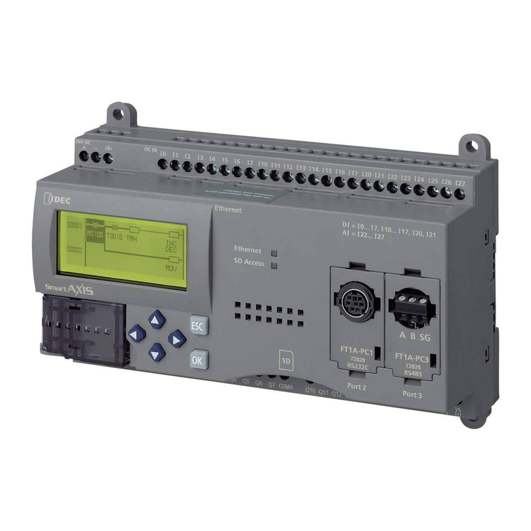
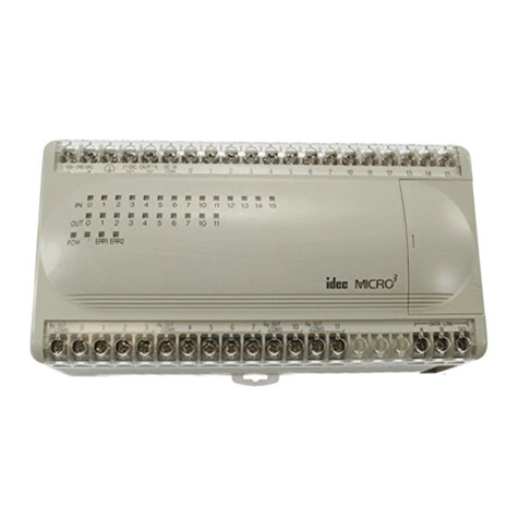
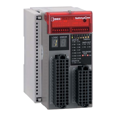
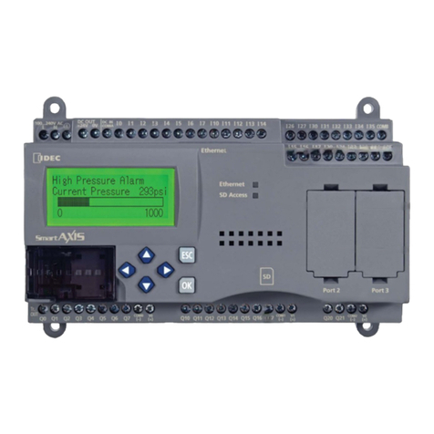
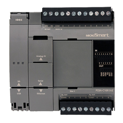
IDEC FC4A-C10R2 User manual

FC4A SERIES
Micro Programmable
Logic Controller
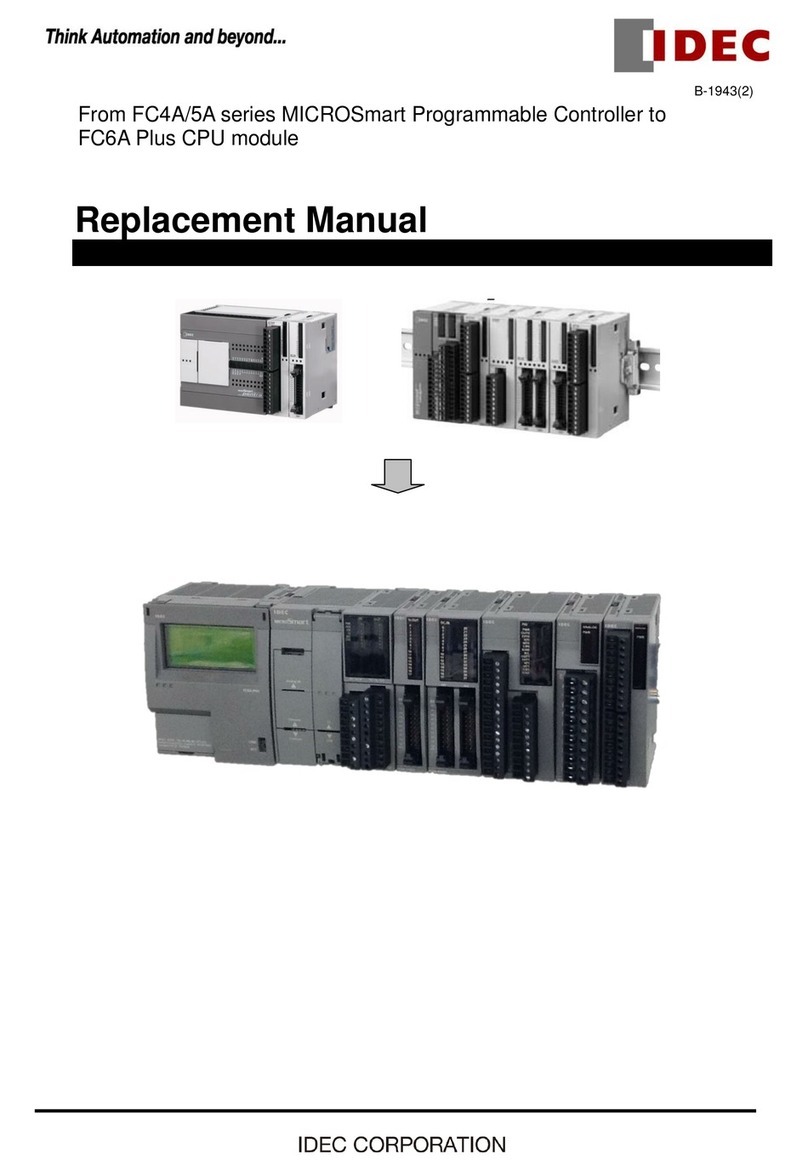
User’s Manual
FC9Y-B812

U
PDATE
I
NFO
« FC4A M
ICRO
S
MART
U
SER
’
S
M
ANUAL
»
M
ICRO
S
MART
U
SER
’
S
M
ANUAL
U
PDATE
Introduction
This manual includes additional descriptions of new modules and upgraded functionality of the FC4A
MicroSmart
CPU
modules with system program version up to 210 in detail.
New Modules
Analog I/O Modules (Ladder Refresh Type)
Upgraded Functionality
Twelve new functions have been implemented in the FC4A
MicroSmart
CPU modules. Availability of the twelve new
functions depends on the model and system program version of the CPU modules as listed below:
To confirm the system program version of the
MicroSmart
CPU module, use
WindLDR
on a computer connected with the
CPU module. Bring
WindLDR
into the online mode. The system program version is indicated on the PLC status dialog
box. For details about the procedure, see page 29-1.
Name I/O Signal I/O Points Type No.
Analog Input Module
Voltage (0 to 10V DC) Current (4 to 20mA)
Thermocouple (K, J, T)
Resistance thermometer (Pt100, Pt1000, Ni100, Ni1000)
4 inputs FC4A-J4CN1
Voltage (0 to 10V DC) Current (4 to 20mA) 8 inputs FC4A-J8C1
Thermistor (NTC, PTC) 8 inputs FC4A-J8AT1
Analog Output Module Voltage (–10 to +10V DC) Current (4 to 20mA) 2 outputs FC4A-K2C1
CPU Module
All-in-One Type Slim Type
FC4A-C10R2
FC4A-C10R2C
FC4A-C16R2
FC4A-C16R2C
FC4A-C24R2
FC4A-C24R2C
FC4A-D20K3
FC4A-D20S3
FC4A-D20RK1
FC4A-D20RS1
FC4A-D40K3
FC4A-D40S3
Analog I/O Modules
(Ladder Refresh Type)
——204 or higher 204 or higher 203 or higher
AS-Interface Master Module
Compatibility
————
201 or higher
64KB Memory Cartridge
Compatibility
PID Instruction Upgrade
202 or higher 202 or higher
HMI Module Initial Screen
Selection
203 or higher 202 or higher
RS485 User Communication
Compatibility
—
204 or higher 204 or higher
204 or higher
202 or higher
User Communication BCC
Upgrade
(ADD-2comp, Modbus ASCII, and
Modbus RTU)
Pulse Instructions Upgrade
—
—
Coordinate Conversion
Instructions Upgrade
204 or higher 203 or higher
Intelligent Module Access
Instructions
Downloading from Memory
Cartridge to CPU Module
210 or higher 210 or higher 210 or higher 210 or higher
User Program Read Prohibit

« FC4A M
ICRO
S
MART
U
SER
’
S
M
ANUAL
»P
REFACE
-1
S
AFETY
P
RECAUTIONS
• Read this user’s manual to make sure of correct operation before starting installation, wiring, operation, maintenance, and
inspection of the
MicroSmart
.
• All
MicroSmart
modules are manufactured under IDEC’s rigorous quality control system, but users must add a backup or
failsafe provision to the control system when using the
MicroSmart
in applications where heavy damage or personal injury
may be caused in case the
MicroSmart
should fail.
• In this user’s manual, safety precautions are categorized in order of importance to Warning and Caution:
•Turn off power to the
MicroSmart
before starting installation, removal, wiring, maintenance, and inspection of the
Micro-
Smart
. Failure to turn power off may cause electrical shocks or fire hazard.
•Special expertise is required to install, wire, program, and operate the
MicroSmart
. People without such expertise must not
use the
MicroSmart
.
•Emergency stop and interlocking circuits must be configured outside the
MicroSmart
. If such a circuit is configured inside
the
MicroSmart
, failure of the
MicroSmart
may cause disorder of the control system, damage, or accidents.
•Install the
MicroSmart
according to the instructions described in this user’s manual. Improper installation will result in fall-
ing, failure, or malfunction of the
MicroSmart
.
• The
MicroSmart
is designed for installation in a cabinet. Do not install the
MicroSmart
outside a cabinet.
• Install the
MicroSmart
in environments described in this user’s manual. If the
MicroSmart
is used in places where the
MicroSmart
is subjected to high-temperature, high-humidity, condensation, corrosive gases, excessive vibrations, and
excessive shocks, then electrical shocks, fire hazard, or malfunction will result.
• The environment for using the
MicroSmart
is “Pollution degree 2.” Use the
MicroSmart
in environments of pollution
degree 2 (according to IEC 60664-1).
• Prevent the
MicroSmart
from falling while moving or transporting the
MicroSmart
, otherwise damage or malfunction of
the
MicroSmart
will result.
• Prevent metal fragments and pieces of wire from dropping inside the
MicroSmart
housing. Put a cover on the
MicroSmart
modules during installation and wiring. Ingress of such fragments and chips may cause fire hazard, damage, or malfunc-
tion.
• Use a power supply of the rated value. Use of a wrong power supply may cause fire hazard.
• Use an IEC 60127-approved fuse on the power line outside the
MicroSmart
. This is required when equipment containing
the
MicroSmart
is destined for Europe.
•Use an IEC 60127-approved fuse on the output circuit. This is required when equipment containing the
MicroSmart
is des-
tined for Europe.
• Use an EU-approved circuit breaker. This is required when equipment containing the
MicroSmart
is destined for Europe.
•Make sure of safety before starting and stopping the
MicroSmart
or when operating the
MicroSmart
to force outputs on or
off. Incorrect operation on the
MicroSmart
may cause machine damage or accidents.
• If relays or transistors in the
MicroSmart
output modules should fail, outputs may remain on or off. For output signals
which may cause heavy accidents, provide a monitor circuit outside the
MicroSmart
.
• Do not connect the ground wire directly to the
MicroSmart
. Connect a protective ground to the cabinet containing the
MicroSmart
using an M4 or larger screw. This is required when equipment containing the
MicroSmart
is destined for
Europe.
• Do not disassemble, repair, or modify the
MicroSmart
modules.
• Dispose of the battery in the
MicroSmart
modules when the battery is dead in accordance with pertaining regulations.
When storing or disposing of the battery, use a proper container prepared for this purpose. This is required when equipment
containing the
MicroSmart
is destined for Europe.
• When disposing of the
MicroSmart
, do so as an industrial waste.
Warning Warning notices are used to emphasize that improper operation may cause
severe personal injury or death.
Caution Caution notices are used where inattention might cause personal injury or
damage to equipment.

P
REFACE
-2 « FC4A M
ICRO
S
MART
U
SER
’
S
M
ANUAL
»
About This Manual
This user’s manual primarily describes entire functions, installation, and programming of the FC4A
MicroSmart
CPU and
all other modules. Also included are powerful communications of the
MicroSmart
and troubleshooting procedures.
C
HAPTER 1: GENERAL INFORMATION
General information about the MicroSmart, features, brief description on special functions, and various system setup con-
figurations for communication.
CHAPTER 2: MODULE SPECIFICATIONS
Specifications of CPU, input, output, mixed I/O, analog I/O, and other optional modules.
CHAPTER 3: INSTALLATION AND WIRING
Methods and precautions for installing and wiring the MicroSmart modules.
CHAPTER 4: OPERATION BASICS
General information about setting up the basic MicroSmart system for programming, starting and stopping MicroSmart
operation, and simple operating procedures from creating a user program using WindLDR on a PC to monitoring the
MicroSmart operation.
CHAPTER 5: SPECIAL FUNCTIONS
Stop/reset inputs, run/stop selection at memory backup error, keep designation for internal relays, shift registers, counters,
and data registers. Also included are high-speed counter, catch input, interrupt input, timer interrupt, input filter, user pro-
gram read/write protection, constant scan time, partial program download, and many more special functions.
CHAPTER 6: ALLOCATION NUMBERS
Allocation numbers available for the MicroSmart CPU modules to program basic and advanced instructions. Special inter-
nal relays and special data registers are also described.
CHAPTER 7: BASIC INSTRUCTIONS
Programming of the basic instructions, available operands, and sample programs.
CHAPTER 8: ADVANCED INSTRUCTIONS
General rules of using advanced instructions, terms, data types, and formats used for advanced instructions.
CHAPTER 9 THROUGH CHAPTER 23:
Detailed descriptions on advanced instructions grouped into 15 chapters.
CHAPTER 24 THROUGH CHAPTER 28:
Analog I/O control and various communication functions such as data link, computer link, modem mode, and AS-Inter-
face.
CHAPTER 29: TROUBLESHOOTING
Procedures to determine the cause of trouble and actions to be taken when any trouble occurs while operating the Micro-
Smart.
APPENDIX
Additional information about execution times for instructions, I/O delay time, and MicroSmart type list.
INDEX
Alphabetical listing of key words.
IMPORTANT INFORMATION
Under no circumstances shall IDEC Corporation be held liable or responsible for indirect or consequential damages resulting
from the use of or the application of IDEC PLC components, individually or in combination with other equipment.
All persons using these components must be willing to accept responsibility for choosing the correct component to suit their
application and for choosing an application appropriate for the component, individually or in combination with other equipment.
All diagrams and examples in this manual are for illustrative purposes only. In no way does including these diagrams and exam-
ples in this manual constitute a guarantee as to their suitability for any specific application. To test and approve all programs,
prior to installation, is the responsibility of the end user.

« FC4A MICROSMART USER’SMANUAL »PREFACE-3
Revision Record
The table below summarizes the changes to this manual since last printing of FC9Y-B812-0A in June, 2006.
Revision Description of Change Page
Analog I/O Modules
(Ladder Refresh Type) Four analog input and output modules are added. 2-43, 6-5,
24-1
AS-Interface Master Module
Compatibility AS-Interface master module is added. 2-57, 6-5,
28-1
RS485 User Communication
Compatibility These functions are now available for FC4A-C16R2, FC4A-
C16R2C, FC4A-C24R2, FC4A-C24R2C, FC4A-D20K3, and
FC4A-D20S3.
17-1
User Communication BCC Upgrade
(ADD-2comp, Modbus ASCII, and Modbus RTU)
Pulse Instructions Upgrade These functions are now available for FC4A-D20K3 and FC4A-
D20S3. 20-1
Coordinate Conversion Instructions
Upgrade These functions are now available for FC4A-C24R2C, FC4A-
D20K3, and FC4A-D20S3.
19-1
Intelligent Module Access Instructions 23-1
Downloading from Memory Cartridge to
CPU Module
A user program can be downloaded from a memory cartridge
to the CPU module. 2-65
User Program Read Prohibit Read protection is upgraded and this option prevents copying
of the user program completely. 5-25

PREFACE-4 « FC4A MICROSMART USER’SMANUAL »

« FC4A MICROSMART USER’SMANUAL »i
TABLE OF CONTENTS
CHAPTER 1: GENERAL INFORMATION
About the MicroSmart . . . . . . . . . . . . . . . . . . . . . . . . . . . . . . . . . . . . . . . . . . . . . 1-1
Features . . . . . . . . . . . . . . . . . . . . . . . . . . . . . . . . . . . . . . . . . . . . . . . . . . . . . . . 1-1
Special Functions . . . . . . . . . . . . . . . . . . . . . . . . . . . . . . . . . . . . . . . . . . . . . . . . 1-2
System Setup . . . . . . . . . . . . . . . . . . . . . . . . . . . . . . . . . . . . . . . . . . . . . . . . . . . 1-4
CHAPTER 2: MODULE SPECIFICATIONS
CPU Modules (All-in-One Type) . . . . . . . . . . . . . . . . . . . . . . . . . . . . . . . . . . . . . . . 2-1
CPU Modules (Slim Type) . . . . . . . . . . . . . . . . . . . . . . . . . . . . . . . . . . . . . . . . . . 2-11
Input Modules . . . . . . . . . . . . . . . . . . . . . . . . . . . . . . . . . . . . . . . . . . . . . . . . . . 2-23
Output Modules . . . . . . . . . . . . . . . . . . . . . . . . . . . . . . . . . . . . . . . . . . . . . . . . 2-30
Mixed I/O Modules . . . . . . . . . . . . . . . . . . . . . . . . . . . . . . . . . . . . . . . . . . . . . . 2-39
Analog I/O Modules . . . . . . . . . . . . . . . . . . . . . . . . . . . . . . . . . . . . . . . . . . . . . . 2-43
AS-Interface Master Module . . . . . . . . . . . . . . . . . . . . . . . . . . . . . . . . . . . . . . . . 2-57
HMI Module . . . . . . . . . . . . . . . . . . . . . . . . . . . . . . . . . . . . . . . . . . . . . . . . . . . 2-59
HMI Base Module . . . . . . . . . . . . . . . . . . . . . . . . . . . . . . . . . . . . . . . . . . . . . . . 2-60
Communication Adapters and Communication Modules . . . . . . . . . . . . . . . . . . . . 2-61
Memory Cartridge . . . . . . . . . . . . . . . . . . . . . . . . . . . . . . . . . . . . . . . . . . . . . . . 2-64
Clock Cartridge . . . . . . . . . . . . . . . . . . . . . . . . . . . . . . . . . . . . . . . . . . . . . . . . . 2-67
Dimensions . . . . . . . . . . . . . . . . . . . . . . . . . . . . . . . . . . . . . . . . . . . . . . . . . . . 2-68
CHAPTER 3: INSTALLATION AND WIRING
Installation Location . . . . . . . . . . . . . . . . . . . . . . . . . . . . . . . . . . . . . . . . . . . . . . 3-1
Assembling Modules . . . . . . . . . . . . . . . . . . . . . . . . . . . . . . . . . . . . . . . . . . . . . . 3-2
Disassembling Modules . . . . . . . . . . . . . . . . . . . . . . . . . . . . . . . . . . . . . . . . . . . . 3-2
Installing the HMI Module . . . . . . . . . . . . . . . . . . . . . . . . . . . . . . . . . . . . . . . . . . 3-3
Removing the HMI Module . . . . . . . . . . . . . . . . . . . . . . . . . . . . . . . . . . . . . . . . . . 3-4
Removing the Terminal Blocks . . . . . . . . . . . . . . . . . . . . . . . . . . . . . . . . . . . . . . . 3-5
Removing the Communication Connector Cover . . . . . . . . . . . . . . . . . . . . . . . . . . . 3-6
Mounting on DIN Rail . . . . . . . . . . . . . . . . . . . . . . . . . . . . . . . . . . . . . . . . . . . . . . 3-7
Removing from DIN Rail . . . . . . . . . . . . . . . . . . . . . . . . . . . . . . . . . . . . . . . . . . . . 3-7
Direct Mounting on Panel Surface . . . . . . . . . . . . . . . . . . . . . . . . . . . . . . . . . . . . . 3-7
Installation in Control Panel . . . . . . . . . . . . . . . . . . . . . . . . . . . . . . . . . . . . . . . . 3-11
Mounting Direction . . . . . . . . . . . . . . . . . . . . . . . . . . . . . . . . . . . . . . . . . . . . . . 3-12
Input Wiring . . . . . . . . . . . . . . . . . . . . . . . . . . . . . . . . . . . . . . . . . . . . . . . . . . . 3-13
Output Wiring . . . . . . . . . . . . . . . . . . . . . . . . . . . . . . . . . . . . . . . . . . . . . . . . . . 3-14
Power Supply . . . . . . . . . . . . . . . . . . . . . . . . . . . . . . . . . . . . . . . . . . . . . . . . . . 3-16
Terminal Connection . . . . . . . . . . . . . . . . . . . . . . . . . . . . . . . . . . . . . . . . . . . . . 3-18
CHAPTER 4: OPERATION BASICS
Connecting MicroSmart to PC (1:1 Computer Link System) . . . . . . . . . . . . . . . . . . . 4-1
Start/Stop Operation . . . . . . . . . . . . . . . . . . . . . . . . . . . . . . . . . . . . . . . . . . . . . . 4-3
Simple Operation . . . . . . . . . . . . . . . . . . . . . . . . . . . . . . . . . . . . . . . . . . . . . . . . 4-5

TABLE OF CONTENTS
ii « FC4A MICROSMART USER’SMANUAL »
CHAPTER 5: SPECIAL FUNCTIONS
Function Area Settings . . . . . . . . . . . . . . . . . . . . . . . . . . . . . . . . . . . . . . . . . . . . . 5-1
Stop Input and Reset Input . . . . . . . . . . . . . . . . . . . . . . . . . . . . . . . . . . . . . . . . . . 5-2
Run/Stop Selection at Memory Backup Error . . . . . . . . . . . . . . . . . . . . . . . . . . . . . 5-3
Keep Designation for Internal Relays, Shift Registers, Counters, and Data Registers 5-4
High-speed Counter . . . . . . . . . . . . . . . . . . . . . . . . . . . . . . . . . . . . . . . . . . . . . . . 5-6
Catch Input . . . . . . . . . . . . . . . . . . . . . . . . . . . . . . . . . . . . . . . . . . . . . . . . . . . . 5-18
Interrupt Input . . . . . . . . . . . . . . . . . . . . . . . . . . . . . . . . . . . . . . . . . . . . . . . . . . 5-20
Timer Interrupt . . . . . . . . . . . . . . . . . . . . . . . . . . . . . . . . . . . . . . . . . . . . . . . . . . 5-22
Input Filter . . . . . . . . . . . . . . . . . . . . . . . . . . . . . . . . . . . . . . . . . . . . . . . . . . . . . 5-24
User Program Protection . . . . . . . . . . . . . . . . . . . . . . . . . . . . . . . . . . . . . . . . . . . 5-25
Constant Scan Time . . . . . . . . . . . . . . . . . . . . . . . . . . . . . . . . . . . . . . . . . . . . . . 5-27
Partial Program Download . . . . . . . . . . . . . . . . . . . . . . . . . . . . . . . . . . . . . . . . . . 5-28
Analog Potentiometers . . . . . . . . . . . . . . . . . . . . . . . . . . . . . . . . . . . . . . . . . . . . 5-30
Analog Voltage Input . . . . . . . . . . . . . . . . . . . . . . . . . . . . . . . . . . . . . . . . . . . . . 5-31
HMI Module . . . . . . . . . . . . . . . . . . . . . . . . . . . . . . . . . . . . . . . . . . . . . . . . . . . . 5-32
Expansion Data Registers . . . . . . . . . . . . . . . . . . . . . . . . . . . . . . . . . . . . . . . . . . 5-42
CHAPTER 6: ALLOCATION NUMBERS
Operand Allocation Numbers . . . . . . . . . . . . . . . . . . . . . . . . . . . . . . . . . . . . . . . . . 6-1
I/O, Internal Relay, and Special Internal Relay Operand Allocation Numbers . . . . . . . 6-3
Operand Allocation Numbers for END Refresh Type Analog I/O Modules . . . . . . . . . 6-5
Operand Allocation Numbers for AS-Interface Master Module 1 . . . . . . . . . . . . . . . . 6-5
Operand Allocation Numbers for Data Link Master Station . . . . . . . . . . . . . . . . . . . 6-6
Operand Allocation Numbers for Data Link Slave Station . . . . . . . . . . . . . . . . . . . . . 6-6
Special Internal Relays . . . . . . . . . . . . . . . . . . . . . . . . . . . . . . . . . . . . . . . . . . . . . 6-7
Special Data Registers . . . . . . . . . . . . . . . . . . . . . . . . . . . . . . . . . . . . . . . . . . . . 6-14
Expansion I/O Module Operands . . . . . . . . . . . . . . . . . . . . . . . . . . . . . . . . . . . . . 6-18
CHAPTER 7: BASIC INSTRUCTIONS
Basic Instruction List . . . . . . . . . . . . . . . . . . . . . . . . . . . . . . . . . . . . . . . . . . . . . . 7-1
LOD (Load) and LODN (Load Not) . . . . . . . . . . . . . . . . . . . . . . . . . . . . . . . . . . . . . 7-2
OUT (Output) and OUTN (Output Not) . . . . . . . . . . . . . . . . . . . . . . . . . . . . . . . . . . . 7-2
SET and RST (Reset) . . . . . . . . . . . . . . . . . . . . . . . . . . . . . . . . . . . . . . . . . . . . . . 7-3
AND and ANDN (And Not) . . . . . . . . . . . . . . . . . . . . . . . . . . . . . . . . . . . . . . . . . . . 7-4
OR and ORN (Or Not) . . . . . . . . . . . . . . . . . . . . . . . . . . . . . . . . . . . . . . . . . . . . . . 7-4
AND LOD (Load) . . . . . . . . . . . . . . . . . . . . . . . . . . . . . . . . . . . . . . . . . . . . . . . . . . 7-5
OR LOD (Load) . . . . . . . . . . . . . . . . . . . . . . . . . . . . . . . . . . . . . . . . . . . . . . . . . . . 7-5
BPS (Bit Push), BRD (Bit Read), and BPP (Bit Pop) . . . . . . . . . . . . . . . . . . . . . . . . . 7-6
TML, TIM, TMH, and TMS (Timer) . . . . . . . . . . . . . . . . . . . . . . . . . . . . . . . . . . . . . 7-7
CNT, CDP, and CUD (Counter) . . . . . . . . . . . . . . . . . . . . . . . . . . . . . . . . . . . . . . . 7-10
CC= and CC≥(Counter Comparison) . . . . . . . . . . . . . . . . . . . . . . . . . . . . . . . . . . 7-14
DC= and DC≥(Data Register Comparison) . . . . . . . . . . . . . . . . . . . . . . . . . . . . . . 7-16
SFR and SFRN (Forward and Reverse Shift Register) . . . . . . . . . . . . . . . . . . . . . . . 7-18
SOTU and SOTD (Single Output Up and Down) . . . . . . . . . . . . . . . . . . . . . . . . . . . 7-22
MCS and MCR (Master Control Set and Reset) . . . . . . . . . . . . . . . . . . . . . . . . . . . 7-23
JMP (Jump) and JEND (Jump End) . . . . . . . . . . . . . . . . . . . . . . . . . . . . . . . . . . . . 7-25
END . . . . . . . . . . . . . . . . . . . . . . . . . . . . . . . . . . . . . . . . . . . . . . . . . . . . . . . . . 7-26

TABLE OF CONTENTS
« FC4A MICROSMART USER’SMANUAL » iii
CHAPTER 8: ADVANCED INSTRUCTIONS
Advanced Instruction List . . . . . . . . . . . . . . . . . . . . . . . . . . . . . . . . . . . . . . . . . . . 8-1
Advanced Instruction Applicable CPU Modules . . . . . . . . . . . . . . . . . . . . . . . . . . . . 8-3
Structure of an Advanced Instruction . . . . . . . . . . . . . . . . . . . . . . . . . . . . . . . . . . . 8-5
Input Condition for Advanced Instructions . . . . . . . . . . . . . . . . . . . . . . . . . . . . . . . 8-5
Source and Destination Operands . . . . . . . . . . . . . . . . . . . . . . . . . . . . . . . . . . . . 8-5
Using Timer or Counter as Source Operand . . . . . . . . . . . . . . . . . . . . . . . . . . . . . . 8-5
Using Timer or Counter as Destination Operand . . . . . . . . . . . . . . . . . . . . . . . . . . . 8-5
Data Types for Advanced Instructions . . . . . . . . . . . . . . . . . . . . . . . . . . . . . . . . . . 8-6
Discontinuity of Operand Areas . . . . . . . . . . . . . . . . . . . . . . . . . . . . . . . . . . . . . . . 8-6
NOP (No Operation) . . . . . . . . . . . . . . . . . . . . . . . . . . . . . . . . . . . . . . . . . . . . . . . 8-7
CHAPTER 9: MOVE INSTRUCTIONS
MOV (Move) . . . . . . . . . . . . . . . . . . . . . . . . . . . . . . . . . . . . . . . . . . . . . . . . . . . . 9-1
MOVN (Move Not) . . . . . . . . . . . . . . . . . . . . . . . . . . . . . . . . . . . . . . . . . . . . . . . . 9-4
IMOV (Indirect Move) . . . . . . . . . . . . . . . . . . . . . . . . . . . . . . . . . . . . . . . . . . . . . . 9-5
IMOVN (Indirect Move Not) . . . . . . . . . . . . . . . . . . . . . . . . . . . . . . . . . . . . . . . . . . 9-6
BMOV (Block Move) . . . . . . . . . . . . . . . . . . . . . . . . . . . . . . . . . . . . . . . . . . . . . . . 9-7
IBMV (Indirect Bit Move) . . . . . . . . . . . . . . . . . . . . . . . . . . . . . . . . . . . . . . . . . . . . 9-8
IBMVN (Indirect Bit Move Not) . . . . . . . . . . . . . . . . . . . . . . . . . . . . . . . . . . . . . . 9-10
CHAPTER 10: DATA COMPARISON INSTRUCTIONS
CMP= (Compare Equal To) . . . . . . . . . . . . . . . . . . . . . . . . . . . . . . . . . . . . . . . . . 10-1
CMP<> (Compare Unequal To) . . . . . . . . . . . . . . . . . . . . . . . . . . . . . . . . . . . . . . 10-1
CMP< (Compare Less Than) . . . . . . . . . . . . . . . . . . . . . . . . . . . . . . . . . . . . . . . . 10-1
CMP> (Compare Greater Than) . . . . . . . . . . . . . . . . . . . . . . . . . . . . . . . . . . . . . . 10-1
CMP<= (Compare Less Than or Equal To) . . . . . . . . . . . . . . . . . . . . . . . . . . . . . . 10-1
CMP>= (Compare Greater Than or Equal To) . . . . . . . . . . . . . . . . . . . . . . . . . . . . 10-1
ICMP>= (Interval Compare Greater Than or Equal To) . . . . . . . . . . . . . . . . . . . . . . 10-4
CHAPTER 11: BINARY ARITHMETIC INSTRUCTIONS
ADD (Addition) . . . . . . . . . . . . . . . . . . . . . . . . . . . . . . . . . . . . . . . . . . . . . . . . . . 11-1
SUB (Subtraction) . . . . . . . . . . . . . . . . . . . . . . . . . . . . . . . . . . . . . . . . . . . . . . . 11-1
MUL (Multiplication) . . . . . . . . . . . . . . . . . . . . . . . . . . . . . . . . . . . . . . . . . . . . . . 11-1
DIV (Division) . . . . . . . . . . . . . . . . . . . . . . . . . . . . . . . . . . . . . . . . . . . . . . . . . . 11-1
ROOT (Root) . . . . . . . . . . . . . . . . . . . . . . . . . . . . . . . . . . . . . . . . . . . . . . . . . . . 11-7
CHAPTER 12: BOOLEAN COMPUTATION INSTRUCTIONS
ANDW (AND Word) . . . . . . . . . . . . . . . . . . . . . . . . . . . . . . . . . . . . . . . . . . . . . . . 12-1
ORW (OR Word) . . . . . . . . . . . . . . . . . . . . . . . . . . . . . . . . . . . . . . . . . . . . . . . . . 12-1
XORW (Exclusive OR Word) . . . . . . . . . . . . . . . . . . . . . . . . . . . . . . . . . . . . . . . . . 12-1
CHAPTER 13: SHIFT / ROTATE INSTRUCTIONS
SFTL (Shift Left) . . . . . . . . . . . . . . . . . . . . . . . . . . . . . . . . . . . . . . . . . . . . . . . . 13-1
SFTR (Shift Right) . . . . . . . . . . . . . . . . . . . . . . . . . . . . . . . . . . . . . . . . . . . . . . . 13-3
BCDLS (BCD Left Shift) . . . . . . . . . . . . . . . . . . . . . . . . . . . . . . . . . . . . . . . . . . . 13-4
WSFT (Word Shift) . . . . . . . . . . . . . . . . . . . . . . . . . . . . . . . . . . . . . . . . . . . . . . . 13-5
ROTL (Rotate Left) . . . . . . . . . . . . . . . . . . . . . . . . . . . . . . . . . . . . . . . . . . . . . . . 13-6
ROTR (Rotate Right) . . . . . . . . . . . . . . . . . . . . . . . . . . . . . . . . . . . . . . . . . . . . . . 13-7

TABLE OF CONTENTS
iv « FC4A MICROSMART USER’SMANUAL »
CHAPTER 14: DATA CONVERSION INSTRUCTIONS
HTOB (Hex to BCD) . . . . . . . . . . . . . . . . . . . . . . . . . . . . . . . . . . . . . . . . . . . . . . 14-1
BTOH (BCD to Hex) . . . . . . . . . . . . . . . . . . . . . . . . . . . . . . . . . . . . . . . . . . . . . . 14-2
HTOA (Hex to ASCII) . . . . . . . . . . . . . . . . . . . . . . . . . . . . . . . . . . . . . . . . . . . . . . 14-3
ATOH (ASCII to Hex) . . . . . . . . . . . . . . . . . . . . . . . . . . . . . . . . . . . . . . . . . . . . . . 14-5
BTOA (BCD to ASCII) . . . . . . . . . . . . . . . . . . . . . . . . . . . . . . . . . . . . . . . . . . . . . 14-7
ATOB (ASCII to BCD) . . . . . . . . . . . . . . . . . . . . . . . . . . . . . . . . . . . . . . . . . . . . . 14-9
ENCO (Encode) . . . . . . . . . . . . . . . . . . . . . . . . . . . . . . . . . . . . . . . . . . . . . . . . 14-11
DECO (Decode) . . . . . . . . . . . . . . . . . . . . . . . . . . . . . . . . . . . . . . . . . . . . . . . . 14-12
BCNT (Bit Count) . . . . . . . . . . . . . . . . . . . . . . . . . . . . . . . . . . . . . . . . . . . . . . . 14-13
ALT (Alternate Output) . . . . . . . . . . . . . . . . . . . . . . . . . . . . . . . . . . . . . . . . . . . 14-14
CHAPTER 15: WEEK PROGRAMMER INSTRUCTIONS
WKTIM (Week Timer) . . . . . . . . . . . . . . . . . . . . . . . . . . . . . . . . . . . . . . . . . . . . . 15-1
WKTBL (Week Table) . . . . . . . . . . . . . . . . . . . . . . . . . . . . . . . . . . . . . . . . . . . . . 15-2
Setting Calendar/Clock Using WindLDR . . . . . . . . . . . . . . . . . . . . . . . . . . . . . . . . 15-5
Setting Calendar/Clock Using a User Program . . . . . . . . . . . . . . . . . . . . . . . . . . . 15-5
Adjusting Clock Using a User Program . . . . . . . . . . . . . . . . . . . . . . . . . . . . . . . . . 15-6
Adjusting Clock Cartridge Accuracy . . . . . . . . . . . . . . . . . . . . . . . . . . . . . . . . . . . 15-7
CHAPTER 16: INTERFACE INSTRUCTIONS
DISP (Display) . . . . . . . . . . . . . . . . . . . . . . . . . . . . . . . . . . . . . . . . . . . . . . . . . . 16-1
DGRD (Digital Read) . . . . . . . . . . . . . . . . . . . . . . . . . . . . . . . . . . . . . . . . . . . . . . 16-3
CHAPTER 17: USER COMMUNICATION INSTRUCTIONS
User Communication Overview . . . . . . . . . . . . . . . . . . . . . . . . . . . . . . . . . . . . . . 17-1
User Communication Mode Specifications . . . . . . . . . . . . . . . . . . . . . . . . . . . . . . 17-2
Connecting RS232C Equipment through RS232C Port 1 or 2 . . . . . . . . . . . . . . . . 17-2
RS232C User Communication System Setup . . . . . . . . . . . . . . . . . . . . . . . . . . . . 17-3
Connecting RS485 Equipment through RS485 Port 2 . . . . . . . . . . . . . . . . . . . . . . 17-4
RS485 User Communication System Setup . . . . . . . . . . . . . . . . . . . . . . . . . . . . . 17-4
Programming WindLDR . . . . . . . . . . . . . . . . . . . . . . . . . . . . . . . . . . . . . . . . . . . . 17-5
TXD1 (Transmit 1) . . . . . . . . . . . . . . . . . . . . . . . . . . . . . . . . . . . . . . . . . . . . . . . 17-6
TXD2 (Transmit 2) . . . . . . . . . . . . . . . . . . . . . . . . . . . . . . . . . . . . . . . . . . . . . . . 17-6
RXD1 (Receive 1) . . . . . . . . . . . . . . . . . . . . . . . . . . . . . . . . . . . . . . . . . . . . . . . 17-15
RXD2 (Receive 2) . . . . . . . . . . . . . . . . . . . . . . . . . . . . . . . . . . . . . . . . . . . . . . . 17-15
User Communication Error . . . . . . . . . . . . . . . . . . . . . . . . . . . . . . . . . . . . . . . . 17-27
ASCII Character Code Table . . . . . . . . . . . . . . . . . . . . . . . . . . . . . . . . . . . . . . . 17-28
RS232C Line Control Signals . . . . . . . . . . . . . . . . . . . . . . . . . . . . . . . . . . . . . . 17-29
Sample Program – User Communication TXD . . . . . . . . . . . . . . . . . . . . . . . . . . . 17-32
Sample Program – User Communication RXD . . . . . . . . . . . . . . . . . . . . . . . . . . . 17-34
CHAPTER 18: PROGRAM BRANCHING INSTRUCTIONS
LABEL (Label) . . . . . . . . . . . . . . . . . . . . . . . . . . . . . . . . . . . . . . . . . . . . . . . . . . 18-1
LJMP (Label Jump) . . . . . . . . . . . . . . . . . . . . . . . . . . . . . . . . . . . . . . . . . . . . . . . 18-1
LCAL (Label Call) . . . . . . . . . . . . . . . . . . . . . . . . . . . . . . . . . . . . . . . . . . . . . . . . 18-3
LRET (Label Return) . . . . . . . . . . . . . . . . . . . . . . . . . . . . . . . . . . . . . . . . . . . . . . 18-3
IOREF (I/O Refresh) . . . . . . . . . . . . . . . . . . . . . . . . . . . . . . . . . . . . . . . . . . . . . . 18-5
DI (Disable Interrupt) . . . . . . . . . . . . . . . . . . . . . . . . . . . . . . . . . . . . . . . . . . . . . 18-7
EI (Enable Interrupt) . . . . . . . . . . . . . . . . . . . . . . . . . . . . . . . . . . . . . . . . . . . . . . 18-7

TABLE OF CONTENTS
« FC4A MICROSMART USER’SMANUAL »v
CHAPTER 19: COORDINATE CONVERSION INSTRUCTIONS
XYFS (XY Format Set) . . . . . . . . . . . . . . . . . . . . . . . . . . . . . . . . . . . . . . . . . . . . . 19-1
CVXTY (Convert X to Y) . . . . . . . . . . . . . . . . . . . . . . . . . . . . . . . . . . . . . . . . . . . . 19-2
CVYTX (Convert Y to X) . . . . . . . . . . . . . . . . . . . . . . . . . . . . . . . . . . . . . . . . . . . . 19-3
CHAPTER 20: PULSE INSTRUCTIONS
PULS1 (Pulse Output 1) . . . . . . . . . . . . . . . . . . . . . . . . . . . . . . . . . . . . . . . . . . . 20-1
PULS2 (Pulse Output 2) . . . . . . . . . . . . . . . . . . . . . . . . . . . . . . . . . . . . . . . . . . . 20-1
PWM1 (Pulse Width Modulation 1) . . . . . . . . . . . . . . . . . . . . . . . . . . . . . . . . . . . 20-7
PWM2 (Pulse Width Modulation 2) . . . . . . . . . . . . . . . . . . . . . . . . . . . . . . . . . . . 20-7
RAMP (Ramp Control) . . . . . . . . . . . . . . . . . . . . . . . . . . . . . . . . . . . . . . . . . . . 20-13
ZRN1 (Zero Return 1) . . . . . . . . . . . . . . . . . . . . . . . . . . . . . . . . . . . . . . . . . . . 20-24
ZRN2 (Zero Return 2) . . . . . . . . . . . . . . . . . . . . . . . . . . . . . . . . . . . . . . . . . . . 20-24
CHAPTER 21: PID INSTRUCTION
PID (PID Control) . . . . . . . . . . . . . . . . . . . . . . . . . . . . . . . . . . . . . . . . . . . . . . . . 21-2
Application Example . . . . . . . . . . . . . . . . . . . . . . . . . . . . . . . . . . . . . . . . . . . . 21-14
CHAPTER 22: DUAL / TEACHING TIMER INSTRUCTIONS
DTML (1-sec Dual Timer) . . . . . . . . . . . . . . . . . . . . . . . . . . . . . . . . . . . . . . . . . . 22-1
DTIM (100-ms Dual Timer) . . . . . . . . . . . . . . . . . . . . . . . . . . . . . . . . . . . . . . . . . 22-1
DTMH (10-ms Dual Timer) . . . . . . . . . . . . . . . . . . . . . . . . . . . . . . . . . . . . . . . . . 22-1
DTMS (1-ms Dual Timer) . . . . . . . . . . . . . . . . . . . . . . . . . . . . . . . . . . . . . . . . . . 22-1
TTIM (Teaching Timer) . . . . . . . . . . . . . . . . . . . . . . . . . . . . . . . . . . . . . . . . . . . . 22-3
CHAPTER 23: INTELLIGENT MODULE ACCESS INSTRUCTIONS
RUNA READ (Run Access Read) . . . . . . . . . . . . . . . . . . . . . . . . . . . . . . . . . . . . . 23-2
RUNA WRITE (Run Access Write) . . . . . . . . . . . . . . . . . . . . . . . . . . . . . . . . . . . . . 23-3
STPA READ (Stop Access Read) . . . . . . . . . . . . . . . . . . . . . . . . . . . . . . . . . . . . . 23-4
STPA WRITE (Stop Access Write) . . . . . . . . . . . . . . . . . . . . . . . . . . . . . . . . . . . . 23-5
CHAPTER 24: ANALOG I/O CONTROL
Applicable CPU Modules . . . . . . . . . . . . . . . . . . . . . . . . . . . . . . . . . . . . . . . . . . 24-1
System Setup . . . . . . . . . . . . . . . . . . . . . . . . . . . . . . . . . . . . . . . . . . . . . . . . . . 24-1
Programming WindLDR . . . . . . . . . . . . . . . . . . . . . . . . . . . . . . . . . . . . . . . . . . . . 24-2
Analog I/O Control Parameters . . . . . . . . . . . . . . . . . . . . . . . . . . . . . . . . . . . . . . 24-7
Data Register Allocation Numbers for Analog I/O Modules . . . . . . . . . . . . . . . . . . 24-8
Analog Input Parameters . . . . . . . . . . . . . . . . . . . . . . . . . . . . . . . . . . . . . . . . . 24-11
Analog Output Parameters . . . . . . . . . . . . . . . . . . . . . . . . . . . . . . . . . . . . . . . . 24-15
CHAPTER 25: DATA LINK COMMUNICATION
Data Link Specifications . . . . . . . . . . . . . . . . . . . . . . . . . . . . . . . . . . . . . . . . . . 25-1
Data Link System Setup . . . . . . . . . . . . . . . . . . . . . . . . . . . . . . . . . . . . . . . . . . 25-2
Data Register Allocation for Transmit/Receive Data . . . . . . . . . . . . . . . . . . . . . . . 25-3
Special Data Registers for Data Link Communication Error . . . . . . . . . . . . . . . . . . 25-4
Data Link Communication between Master and Slave Stations . . . . . . . . . . . . . . . 25-5
Special Internal Relays for Data Link Communication . . . . . . . . . . . . . . . . . . . . . . 25-6
Programming WindLDR . . . . . . . . . . . . . . . . . . . . . . . . . . . . . . . . . . . . . . . . . . . . 25-7
Refresh Mode . . . . . . . . . . . . . . . . . . . . . . . . . . . . . . . . . . . . . . . . . . . . . . . . . . 25-9
Operating Procedure for Data Link System . . . . . . . . . . . . . . . . . . . . . . . . . . . . . 25-11
Data Link with Other PLCs . . . . . . . . . . . . . . . . . . . . . . . . . . . . . . . . . . . . . . . . 25-12

TABLE OF CONTENTS
vi « FC4A MICROSMART USER’SMANUAL »
CHAPTER 26: COMPUTER LINK COMMUNICATION
Computer Link System Setup (1:N Computer Link System) . . . . . . . . . . . . . . . . . . 26-1
Programming WindLDR . . . . . . . . . . . . . . . . . . . . . . . . . . . . . . . . . . . . . . . . . . . . 26-2
Monitoring PLC Status . . . . . . . . . . . . . . . . . . . . . . . . . . . . . . . . . . . . . . . . . . . . 26-3
RS232C/RS485 Converter FC2A-MD1 . . . . . . . . . . . . . . . . . . . . . . . . . . . . . . . . . 26-4
CHAPTER 27: MODEM MODE
System Setup . . . . . . . . . . . . . . . . . . . . . . . . . . . . . . . . . . . . . . . . . . . . . . . . . . 27-1
Applicable Modems . . . . . . . . . . . . . . . . . . . . . . . . . . . . . . . . . . . . . . . . . . . . . . 27-2
Special Internal Relays for Modem Mode . . . . . . . . . . . . . . . . . . . . . . . . . . . . . . . 27-2
Special Data Registers for Modem Mode . . . . . . . . . . . . . . . . . . . . . . . . . . . . . . . 27-3
Originate Mode . . . . . . . . . . . . . . . . . . . . . . . . . . . . . . . . . . . . . . . . . . . . . . . . . 27-3
Disconnect Mode . . . . . . . . . . . . . . . . . . . . . . . . . . . . . . . . . . . . . . . . . . . . . . . . 27-5
AT General Command Mode . . . . . . . . . . . . . . . . . . . . . . . . . . . . . . . . . . . . . . . . 27-5
Answer Mode . . . . . . . . . . . . . . . . . . . . . . . . . . . . . . . . . . . . . . . . . . . . . . . . . . . 27-6
Modem Mode Status Data Register . . . . . . . . . . . . . . . . . . . . . . . . . . . . . . . . . . . 27-7
Initialization String Commands . . . . . . . . . . . . . . . . . . . . . . . . . . . . . . . . . . . . . . 27-8
Preparation for Using Modem . . . . . . . . . . . . . . . . . . . . . . . . . . . . . . . . . . . . . . . 27-9
Programming Data Registers and Internal Relays . . . . . . . . . . . . . . . . . . . . . . . . . 27-9
Setting Up the CPU Module . . . . . . . . . . . . . . . . . . . . . . . . . . . . . . . . . . . . . . . . 27-9
Programming WindLDR . . . . . . . . . . . . . . . . . . . . . . . . . . . . . . . . . . . . . . . . . . . 27-10
Operating Procedure for Modem Mode . . . . . . . . . . . . . . . . . . . . . . . . . . . . . . . . 27-11
Sample Program for Modem Originate Mode . . . . . . . . . . . . . . . . . . . . . . . . . . . 27-12
Sample Program for Modem Answer Mode . . . . . . . . . . . . . . . . . . . . . . . . . . . . . 27-13
Troubleshooting in Modem Communication . . . . . . . . . . . . . . . . . . . . . . . . . . . . 27-14
CHAPTER 28: AS-INTERFACE MASTER COMMUNICATION
About AS-Interface . . . . . . . . . . . . . . . . . . . . . . . . . . . . . . . . . . . . . . . . . . . . . . . 28-1
Operation Basics . . . . . . . . . . . . . . . . . . . . . . . . . . . . . . . . . . . . . . . . . . . . . . . . 28-6
Pushbuttons and LED Indicators . . . . . . . . . . . . . . . . . . . . . . . . . . . . . . . . . . . . 28-14
AS-Interface Operands . . . . . . . . . . . . . . . . . . . . . . . . . . . . . . . . . . . . . . . . . . . 28-18
Using Two AS-Interface Master Modules . . . . . . . . . . . . . . . . . . . . . . . . . . . . . . 28-32
Using WindLDR . . . . . . . . . . . . . . . . . . . . . . . . . . . . . . . . . . . . . . . . . . . . . . . . 28-34
SwitchNet Data I/O Port (AS-Interface Master Module 1) . . . . . . . . . . . . . . . . . . . 28-39
CHAPTER 29: TROUBLESHOOTING
ERR LED . . . . . . . . . . . . . . . . . . . . . . . . . . . . . . . . . . . . . . . . . . . . . . . . . . . . . . 29-1
Reading Error Data . . . . . . . . . . . . . . . . . . . . . . . . . . . . . . . . . . . . . . . . . . . . . . . 29-1
Special Data Registers for Error Information . . . . . . . . . . . . . . . . . . . . . . . . . . . . . 29-3
General Error Codes . . . . . . . . . . . . . . . . . . . . . . . . . . . . . . . . . . . . . . . . . . . . . . 29-3
CPU Module Operating Status, Output, and ERR LED during Errors . . . . . . . . . . . . 29-4
Error Causes and Actions . . . . . . . . . . . . . . . . . . . . . . . . . . . . . . . . . . . . . . . . . . 29-4
User Program Execution Error . . . . . . . . . . . . . . . . . . . . . . . . . . . . . . . . . . . . . . . 29-6
Troubleshooting Diagrams . . . . . . . . . . . . . . . . . . . . . . . . . . . . . . . . . . . . . . . . . 29-7
Restriction on Ladder Programming . . . . . . . . . . . . . . . . . . . . . . . . . . . . . . . . . . 29-22
APPENDIX Execution Times for Instructions . . . . . . . . . . . . . . . . . . . . . . . . . . . . . . . . . . . . . 30-1
Breakdown of END Processing Time . . . . . . . . . . . . . . . . . . . . . . . . . . . . . . . . . . 30-2
I/O Delay Time . . . . . . . . . . . . . . . . . . . . . . . . . . . . . . . . . . . . . . . . . . . . . . . . . 30-2
Instruction Steps and Applicability in Interrupt Programs . . . . . . . . . . . . . . . . . . . . 30-3
Cables . . . . . . . . . . . . . . . . . . . . . . . . . . . . . . . . . . . . . . . . . . . . . . . . . . . . . . . 30-4
Type List . . . . . . . . . . . . . . . . . . . . . . . . . . . . . . . . . . . . . . . . . . . . . . . . . . . . . . 30-7
INDEX

« FC4A MICROSMART USER’SMANUAL » 1-1
1: GENERAL INFORMATION
Introduction
This chapter describes general information for understanding the MicroSmart’s powerful capabilities and system setups to
use the MicroSmart in various ways of communication.
About the MicroSmart
IDEC’s MicroSmart is a new family of micro programmable logic controllers available in two styles of CPU modules; all-
in-one and slim types. The all-in-one type CPU module has 10, 16, or 24 I/O terminals and is equipped with a built-in uni-
versal power supply to operate on 100 to 240V AC or 24V DC. Using four 16-point I/O modules, the 24-I/O type CPU
module can expand the I/O points up to a total of 88 points. The slim type CPU module has 20 or 40 I/O terminals and
operates on 24V DC. The total I/O points can be expanded to a maximum of 264.
User programs for the MicroSmart can be edited using WindLDR on a Windows PC. Since WindLDR can load existing user
programs made for IDEC’s previous PLCs such as all FA series, MICRO-1, MICRO3, MICRO3C, and OpenNet Controller,
your software assets can be used in the new control system.
Program capacity of the all-in-one type CPU modules is 4,800 bytes (800 steps) on the 10-I/O type CPU module, 15,000
bytes (2,500 steps) on the 16-I/O type, and 27,000 bytes (4,500 steps) on the 24-I/O type. Slim type CPU modules have a
program capacity of 27,000 bytes (4,500 steps) or 31,200 bytes (5,200 steps). When using an optional 64KB memory car-
tridge on slim type CPU modules, the program capacity can be expanded up to 64,500 bytes (10,750 steps).
Features
Powerful Communication Functions
The MicroSmart features four powerful communication functions.
Communication Adapter (All-in-one 16- and 24-I/O type CPU modules)
Communication Module (Slim type CPU modules)
In addition to the standard RS232C port 1, the all-in-one 16- and 24-I/O type CPU modules feature a port 2 connector to
install an optional RS232C or RS485 communication adapter. All slim type CPU modules can be used with an optional
RS232C or RS485 communication module to add communication port 2. With an optional HMI base module mounted
with a slim type CPU module, an optional RS232C or RS485 communication adapter can also be installed on the HMI
base module.
Maintenance
Communication
(Computer Link)
When a MicroSmart CPU module is connected to a computer, operating status and I/O status
can be monitored on the computer, data in the CPU can be monitored or updated, and user
programs can be downloaded and uploaded. All CPU modules (except the all-in-one 10-I/O
type) can set up a 1:N computer link system to connect a maximum of 32 CPU modules to a
computer.
User Communication
All MicroSmart CPU modules can be linked to external RS232C devices such as computers,
printers, and barcode readers, using the user communication function. RS485 user communi-
cation is also available on upgraded CPU modules of slim 20-I/O relay output and 40-I/O
types.
Modem Communication All MicroSmart CPU modules (except the all-in-one 10-I/O type) can communicate through
modems using the built-in modem protocol.
Data Link
All MicroSmart CPU modules (except the all-in-one 10-I/O type) can set up a data link system.
One CPU module at the master station can communicate with 31 slave stations through an
RS485 line to exchange data and perform distributed control effectively.
RS232C Communication Adapter
RS232C Communication Module
Used for computer link 1:1 communication, user communication, and modem
communication.
RS485 Communication Adapter
RS485 Communication Module
Available in mini DIN connector and terminal block styles. Used for computer link
1:1 or 1:N communication, user communication, and data link communication.

1: GENERAL INFORMATION
1-2 « FC4A MICROSMART USER’SMANUAL »
HMI Module (all CPU modules)
An optional HMI module can be installed on any all-in-one type CPU module, and also on the HMI base module mounted
next to any slim type CPU module. The HMI module makes it possible to manipulate the RAM data in the CPU module
without using the Online menu options in WindLDR.
HMI module functions include:
•Displaying timer/counter current values and changing timer/counter preset values
•Displaying and changing data register values
•Setting and resetting bit operand statuses, such as inputs, outputs, internal relays, and shift register bits
•Displaying and clearing error data
•Starting and stopping the PLC
•Displaying and changing calendar/clock data (only when using the clock cartridge)
•Confirming changed timer/counter preset values
Clock Cartridge (all CPU modules)
An optional clock cartridge can be installed on the CPU module to store real time calendar/clock data for use with
advanced instructions to perform time-scheduled control.
Memory Cartridge (all CPU modules)
A user program can be stored on an optional memory cartridge using WindLDR. The memory cartridge can be installed on
another CPU module to replace user programs without the need for connecting to a computer. The original user program in
the CPU module is restored after removing the memory cartridge. The user program on the memory cartridge can also be
downloaded to the CPU module. The download option is selected using WindLDR.
Analog I/O Modules (all CPU modules except the all-in-one 10- and 16-I/O types)
Analog I/O modules are available in 3-I/O types, 2-input type, and 1-output type. The input channel can accept either volt-
age (0 to 10V DC) and current (4 to 20 mA) signals or thermocouple (types K, J, and T) and resistance thermometer (Pt
100) signals. The output channel generates voltage (0 to 10V DC) and current (4 to 20 mA) signals.
AS-Interface Master Module (slim type 20-I/O relay output and 40-I/O types)
Four upgraded slim type CPU modules (FC4A-D20RK1, FC4A-D20RS1, FC4A-D40K3, and FC4A-D40S3) with system
program ver. 201 and higher can use the AS-Interface master module, and have additional internal relays and data registers
to communicate with slaves, such as actuators and sensors, through the AS-Interface bus. For details about AS-Interface
module and AS-Interface communication, see page 2-57 and chapter 28.
Special Functions
The MicroSmart features various special functions packed in the small housing as described below. For details about these
functions, see the following chapters.
Stop and Reset Inputs
Any input terminal on the CPU module can be designated as a stop or reset input to control the MicroSmart operation.
RUN/STOP Selection at Startup when “Keep” Data is Broken
When data to be kept such as “keep” designated counter values are broken while the CPU is powered down, the user can
select whether the CPU starts to run or not to prevent undesirable operation at the next startup.
“Keep” or “Clear” Designation of CPU Data
Internal relays, shift register bits, counter current values, and data register values can be designated to be kept or cleared
when the CPU is powered down. All or a specified range of these operands can be designated as keep or clear types.
High-speed Counter
The MicroSmart has four built-in high-speed counters to make it possible to count up to 65,535 (FFFFh) high-speed pulses
which cannot be counted by the normal user program processing. One high-speed counter (all-in-one type CPU modules)
or two high-speed counters (slim type CPU modules) can be used as either two-phase or single-phase high-speed counters
at a maximum count input frequency of 20 kHz. Three or two others are single-phase high-speed counters with a maxi-
mum counting frequency of 5 kHz. The high-speed counters can be used for simple positioning control and simple motor
control.

1: GENERAL INFORMATION
« FC4A MICROSMART USER’SMANUAL » 1-3
Catch Input
Four inputs can be used as catch inputs. The catch input makes sure to receive short input pulses (rising pulse of 40 µs or
falling pulse of 150 µs minimum) from sensors without regard to the scan time.
Interrupt Input
Four inputs can be used as interrupt inputs. When a quick response to an external input is required, such as positioning
control, the interrupt input can call a subroutine to execute an interrupt program.
Timer Interrupt
In addition to the interrupt input, slim type CPU modules FC4A-D20RK1, FC4A-D20RS1, FC4A-D40K1, and FC4A-
D40S1 have a timer interrupt function. When a repetitive operation is required, the timer interrupt can be used to call a
subroutine repeatedly at predetermined intervals of 10 through 140 ms.
Input Filter
The input filter can be adjusted for eight inputs to reject input noises. Selectable input filter values to pass input signals are
0 ms, and 3 through 15 ms in 1-ms increments. The input filter rejects inputs shorter than the selected input filter value
minus 2 ms. This function is useful for eliminating input noises and chatter in limit switches.
User Program Read/Write Protection
The user program in the CPU module can be protected against reading and/or writing by including a password in the user
program. Read protection without a password is also available to inhibit reading completely.
Constant Scan Time
The scan time may vary whether basic and advanced instructions are executed or not depending on input conditions to
these instructions. When performing repetitive control, the scan time can be made constant by entering a required scan
time value into a special data register reserved for constant scan time.
Partial Program Download
Normally, the CPU module has to be stopped before downloading a user program. All CPU modules (except the all-in-one
10-I/O type) have run-time program download capabilities to download a user program containing small changes while the
CPU is running in either 1:1 or 1:N computer link system. This function is particularly useful to make small modifications
to the user program and confirm the changes while the CPU is running.
Analog Potentiometer
All CPU modules have an analog potentiometer, except the all-in-one 24-I/O type CPU module has two analog potentiom-
eters. The values (0 through 255) set with analog potentiometers 1 and 2 are stored to special data registers. The analog
potentiometer can be used to change the preset value for a timer or counter.
Analog Voltage Input
Every slim type CPU module has an analog voltage input connector. When an analog voltage of 0 through 10V DC is
applied to the analog voltage input connector, the signal is converted to a digital value of 0 through 255 and stored to a spe-
cial data register. The data is updated in every scan.
Pulse Output
Slim type CPU modules have pulse output instructions to generate high-speed pulse outputs from transistor output termi-
nals used for simple position control applications, illumination control, trapezoidal control, and zero-return control.
PID Control
All CPU modules (except the all-in-one 10- and 16-I/O types) have the PID instruction, which implements a PID (propor-
tional, integral, and derivative) algorithm with built-in auto tuning to determine PID parameters. This instruction is prima-
rily designed for use with an analog I/O module to read analog input data, and turns on and off a designated output to
perform PID control in applications such as temperature control. In addition, the PID instruction can also generate an ana-
log output using an analog I/O module.
Expansion Data Register
Slim type CPU modules FC4A-D20RK1, FC4A-D20RS1, FC4A-D40K3, and FC4A-D40S3 have expansion data registers
D2000 through D7999. Numerical data can be set to expansion data registers using WindLDR. When downloading the user
program, the preset values of the expansion data registers are also downloaded to the EEPROM in the CPU module. Since
the data in the EEPROM is non-volatile, the preset values of the expansion data registers are maintained semi-permanently
and loaded to the RAM each time the CPU is powered up.

1: GENERAL INFORMATION
1-4 « FC4A MICROSMART USER’SMANUAL »
System Setup
This section illustrates system setup configurations for using powerful communication functions of the MicroSmart.
User Communication and Modem Communication System
The all-in-one 16- and 24-I/O type MicroSmart CPU modules have port 1 for RS232C communication and port 2 connec-
tor. An optional RS232C or RS485 communication adapter can be installed on the port 2 connector. With an RS232C com-
munication adapter installed on port 2, the 16- or 24-I/O type MicroSmart CPU module can communicate with two
RS232C devices at the same time.
The figure below illustrates a system setup of user communication and modem communication. In this example, the oper-
ating status of a remote machine is monitored on a computer through modems connected to port 2 and the data is trans-
ferred through port 1 to a pager transmitter using the user communication.
The same system can be set up using any slim type CPU module and an optional RS232C communication module.
For details about the user communication, see page 17-1.
For details about the modem mode, see page 27-1.
All-in-One 16- or 24-I/O Type CPU Module
Pager Transmitter
Pager
Modem
Data
Communication
Modem
Computer
Data
Transmission
RS232C
Communication
Adapter on
Port 2 Connector
Port 1

1: GENERAL INFORMATION
« FC4A MICROSMART USER’SMANUAL » 1-5
Computer Link System
When the MicroSmart is connected to a computer, operating status and I/O status can be monitored on the computer, data
in the CPU module can be monitored or updated, and user programs can be downloaded and uploaded. When an optional
RS485 communication adapter is installed on the port 2 connector of the all-in-one 16- or 24-I/O type CPU modules or
when an optional RS485 communication module is mounted with any slim type CPU modules, a maximum of 32 CPU
modules can be connected to one computer in the 1:N computer link system.
For details about the computer link communication, see pages 4-1 and 26-1.
Computer Link 1:1 Communication
Computer Link 1:N Communication
Slim Type CPU Module
Computer Link Cable 4C
FC2A-KC4C
3m (9.84 ft.) long
All-in-One Type CPU Module
Port 1
RS232C Communication
Adapter on Port 2 Connector
Port 2
Computer Link Cable 4C
FC2A-KC4C
3m (9.84 ft.) long
Port 1
RS232C Communication Module
RS485 Communication
Adapter on Port 2 Connector
All-in-One 16- or 24-I/O Type CPU Module
RS232C Cable
HD9Z-C52
1.5m (4.92 ft.) long
RS232C/RS485 Converter
FC2A-MD1
Twisted-pair Shielded Cable
1st Unit
2nd Unit
32nd Unit
Slim Type CPU Module
Port 2
RS485 Communication Module

1: GENERAL INFORMATION
1-6 « FC4A MICROSMART USER’SMANUAL »
Data Link System
With an optional RS485 communication adapter installed on the port 2 connector, one 16- or 24-I/O type CPU module at
the master station can communicate with 31 slave stations through the RS485 line to exchange data and perform distrib-
uted control effectively. The RS485 terminals are connected with each other using a 2-core twisted pair cable.
The same data link system can also be set up using any slim type CPU modules mounted with RS485 communication
modules.
For details about the data link communication, see page 25-1.
Basic System
The all-in-one 10-I/O type CPU module has 6 input terminals and 4 output terminals. The 16-I/O type CPU module has 9
input terminals and 7 output terminals. The 24-I/O type CPU module has 14 input terminals and 10 output terminals. Only
the 24-I/O type CPU module has an expansion connector to connect I/O modules. When four 16-point input or output
modules are connected to the 24-I/O type CPU module, the I/O points can be expanded to a maximum of 88 points.
Any slim type CPU module can add a maximum of seven expansion I/O modules.
Master Station Slave Station 1 Slave Station 31
4 I/O modules maximumAll-in-One 24-I/O Type CPU Module

1: GENERAL INFORMATION
« FC4A MICROSMART USER’SMANUAL » 1-7
Operator Interface Communication System
The MicroSmart can communicate with IDEC’s HG series operator interfaces through RS232C port 1 and port 2.
Optional cables are available for connection between the MicroSmart and HG series operator interfaces. When installing
an optional RS232C communication adapter on the all-in-one type CPU module or an optional RS232C communication
module on the slim type CPU module, two operator interfaces can be connected to one MicroSmart CPU module.
For details about communication settings, see the user’s manual for the operator interface.
Applicable Cables to Operator Interfaces
Operator Interface O/I Communication Cable For Use on MicroSmart
HG1B, HG2A Series FC4A-KC1C RS232C port 1 and port 2
HG9Z-XC183 Port 2 only
HG2F, HG3F, HG4F Series FC4A-KC2C RS232C port 1 and port 2
HG9Z-3C125 Port 2 only
HG series Operator Interface
To RS232C Port 1 or 2
O/I Communication Cable

1: GENERAL INFORMATION
1-8 « FC4A MICROSMART USER’SMANUAL »
AS-Interface Network
The MicroSmart can be connected to the AS-Interface network using the AS-Interface master module (FC4A-AS62M).
AS-Interface is a type of field bus that is primarily intended to be used to control sensors and actuators. AS-Interface is a
network system that is compatible with the IEC62026 standard and is not proprietary to any one manufacturer. A master
device can communicate with slave devices such as sensors, actuators, and remote I/Os, using digital and analog signals
transmitted over the AS-Interface bus.
The AS-Interface system is comprised of the following three major components:
•One master, such as the MicroSmart AS-Interface master module
•One or more slave devices, such as sensors, actuators, switches, and indicators
•Dedicated 30V DC AS-Interface power supply (26.5 to 31.6V DC)
These components are connected using a two-core cable for both data transmission and AS-Interface power supply. AS-
Interface employs a simple yet efficient wiring system and features automatic slave address assignment function, while
installation and maintenance are also very easy.
For details about AS-Interface communication, see see page 2-57 and chapter 28.
Actuator-Sensor-Interface, abbreviated AS-Interface
Light Curtain
Open Network (DeviceNet, CC-Link)
AS-Interface
Gateway
AS-Interface
Safety Monitor
AS-Interface Safety at Work
Emergency
Stop Switch
Manifold Solenoid Valve
Light Tower
(AS-Interface
Direct
Connection Type)
MicroSmart AS-Interface Master Module
PS2R AS-Interface Power Supply
SX5A AS-Interface
Communication Terminal
IP67 Outside-panel Type
SX5A AS-Interface
Communication Terminal
IP20 Inside-panel Type
SwitchNet Control Units
(AS-Interface Direct Connection Type)
Sensor
(AS-Interface Direct
Connection Type)
Sensor
The AS-Interface Safety Monitor is required
to connect safety devices, such as the light
curtain and emergency stop switch, to the
AS-Interface line.
SwitchNet is an IDEC trademark for pushbuttons, pilot lights, and other control units
capable of direct connection to the AS-Interface. SwitchNet devices are completely
compatible with AS-Interface Ver. 2.1.
TM
Maximum Communication Distance
Without repeater: 100 m
With 2 repeaters: 300 m
This manual suits for next models
11
Table of contents
Other IDEC Controllers manuals
IDEC
IDEC MICROSmart FC6A Series Owner's manual
IDEC
IDEC MICROSmart FC4A Series Operating and safety instructions
IDEC
IDEC MICRO3 User manual
IDEC
IDEC SmartAXIS Touch FT1A Series User manual

IDEC
IDEC HS1 Series User manual
IDEC
IDEC SE9Z-HC User manual
IDEC
IDEC MICROSmart FC5A Series User manual
IDEC
IDEC microsmart pentra Owner's manual

IDEC
IDEC HS9Z-FL54 User manual
IDEC
IDEC OpenNet series User manual
