Panduit Atlona AT-HDVS-CAM-HDBT-BK User manual

Installation Guide
AT-HDVS-CAM-HDBT-BK / AT-HDVS-CAM-HDBT-WH
1
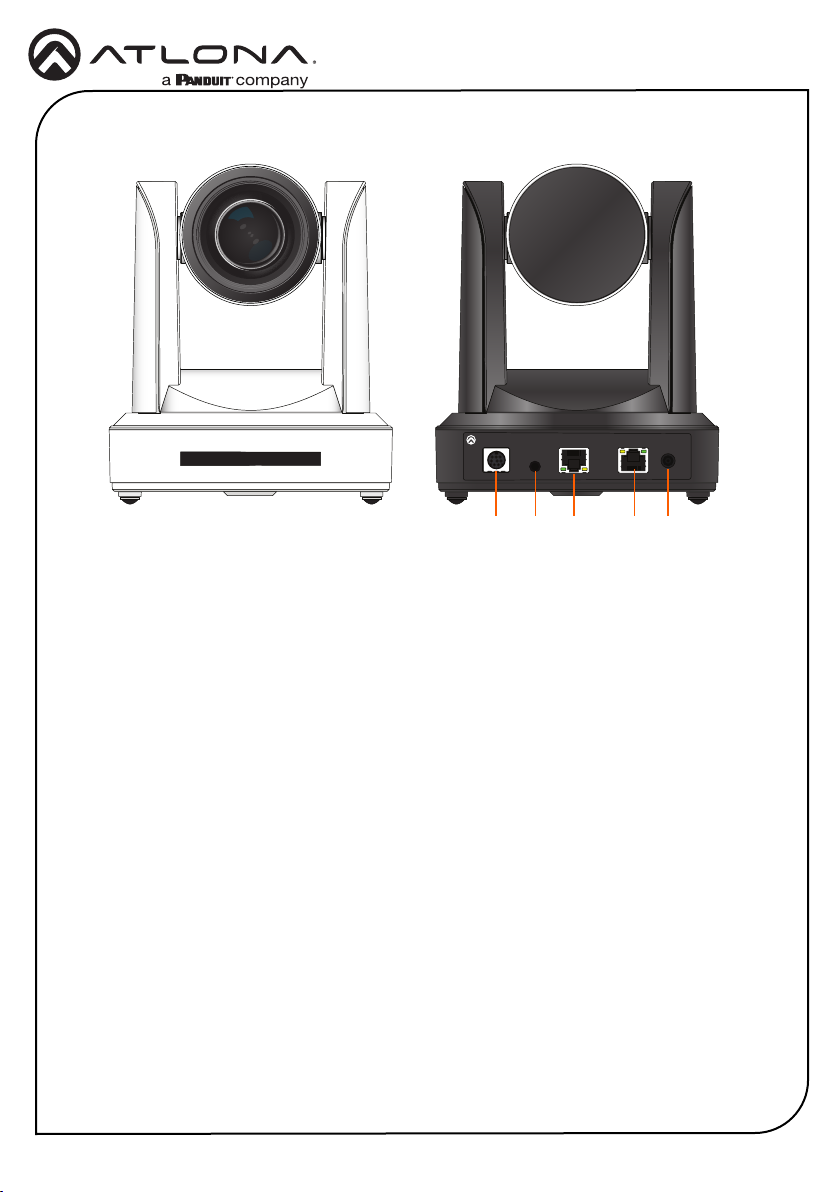
PTZ Camera with HDBaseT Output
AT-HDVS-CAM-HDBT-BK and AT-HDVS-CAM-HDBT-WH
The Atlona AT-HDVS-CAM-HDBT is an enterprise-grade PTZ camera designed for use in
video conferencing and other applications such as lecture capture and distance learning. It
features an HDBaseT output for extending video, power, and camera control over distances up
to 330 feet (100 meters). The HDVS-CAM-HDBT is ideal for remotely interfacing into HDBaseT
equipped switchers and extenders, for use with a video conferencing codec, lecture capture
appliance, or PC equipped for video capture. Camera control over HDBaseT or TCP/IP facilitates
remote integration into AV control systems. The HDVS-CAM-HDBT delivers high performance,
professional-quality imaging with video resolutions up to 1080p @ 60 Hz, as well as fast and
accurate auto-focusing, and a fast yet quiet pan and tilt mechanism. Also available is H.264 or
H.265 streaming over IP with support for RTMP and RTSP protocols. This PTZ camera is ideal for
large meeting spaces, classrooms, training rooms, and many other environments. The HDVS-
CAM-HDBT is available in black or white.
1 x AT-HDVS-CAM-HDBT-BK or
AT-HDVS-CAM-HDBT-WH
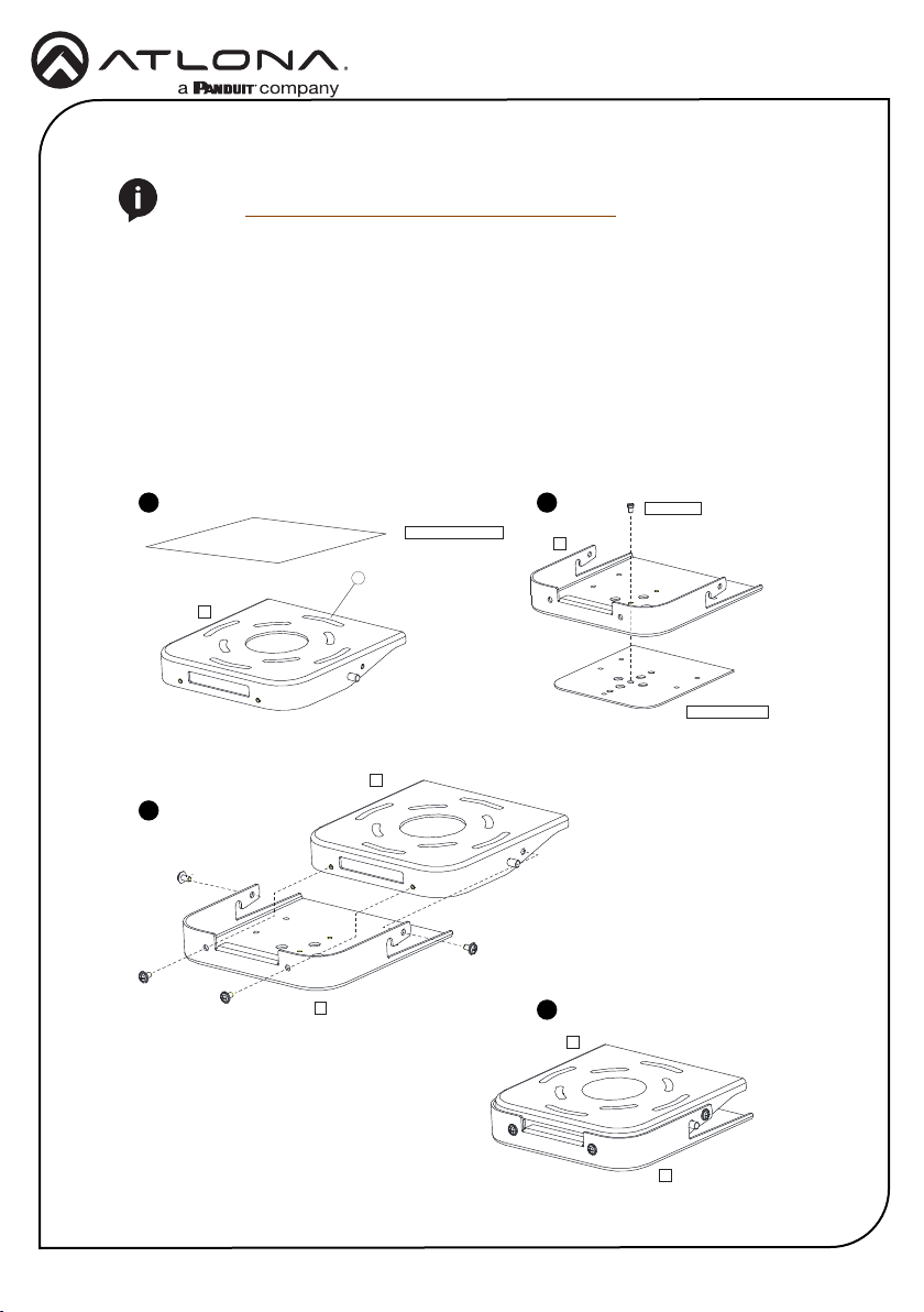
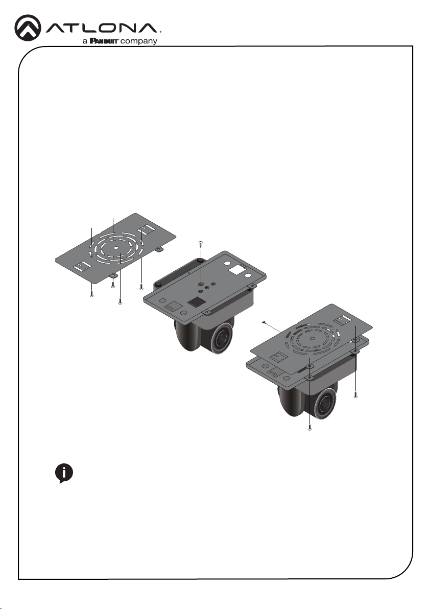
1 x Wall mounting plate
1 x 1/4-20 UNC screw
1 x IR Remote Control
1 x USB A cable
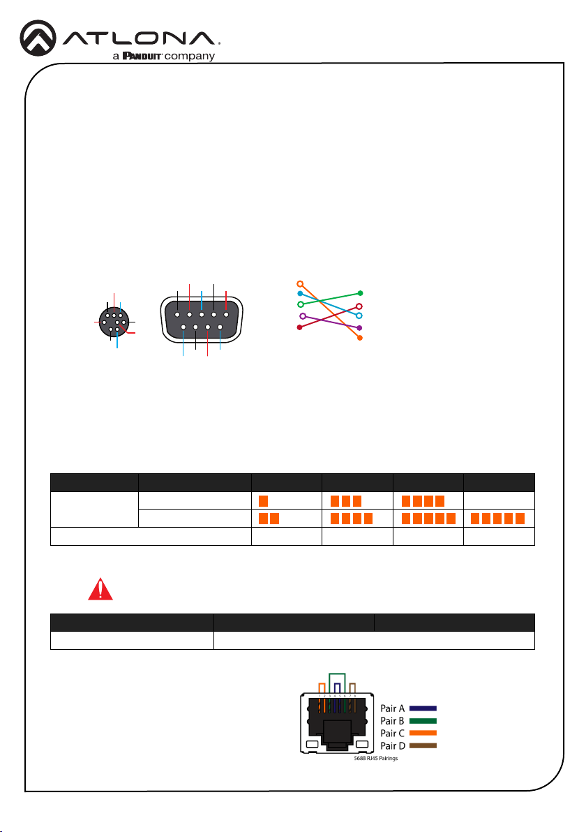
1 x VISCA to RS-232 DB-9 adapter
2 x AAA battery
1 x Installation Guide
Package Contents

Installation Guide
AT-HDVS-CAM-HDBT-BK / AT-HDVS-CAM-HDBT-WH
2
1 RS-232
Connect included VISCA to RS-232
adapter here to control the camera with a
third party software or hardware controller.
2 AUDIO IN
Connect a 3.5 mm audio cable from an
audio source, to this port, to embed audio
with video when network streaming.
3 HDBaseT OUT
Connect to a compatible PoE switcher
or receiver, such as: AT-OME-RX11, AT-
OME-PS62, etc.
4 LAN
Connect to a network switch to control
the unit via TCP/IP or webGUI.
5 DC 12V
Connect the included 12V power supply
to this port.
Panel Descriptions
1
0
X
Z
o
o
m
F
1
.
6
-
F
3
.
0
f
4
.
7
m
m
-
f
4
7
m
m
1
0
X
Z
o
o
m
F
1
.
6
-
F
3
.
0
f
4
.
7
m
m
-
f
4
7
m
m
RS-232 AUDIO
IN
LANHDBaseT OUT
DC 12V
AT-HDVS-CAM-HDBT-BK
21 3 54

Installation Guide
AT-HDVS-CAM-HDBT-BK / AT-HDVS-CAM-HDBT-WH
3
Mounting Instructions
The AT-HDVS-CAM-HDBT has two installation options, wall mount (included) and ceiling mount
(purchased separately).
Wall Mount Installation
The install the AT-HDVS-CAM-HDBT, 4 M6 swelling bolts, 1 1/4-20 UNC screw, 4 M6 nuts and
shims, the included wall mount bracket, and the AT-HDVS-CAM-HDBT are required.
1 Install the M6 swelling bolts in a rectangular pattern on the wall, 100 mm wide and 50 mm
high.
2 Attached the wall mount bracket onto the wall, by placing them on the M6 swelling bolts
and securing it with the M6 nuts and shims.
3 Once the wall mount bracket is secure on the wall, place the camera on the top of the wall
mount bracket and secure it with the 1/4-20 UNC screw.
1
0
X
Z
o
o
m
F
1
.
6
-
F
3
.
0
f
4
.
7
m
m
-
f
4
7
m
m
1
0
X
Z
o
o
m
F
1
.
6
-
F
3
.
0
-
f
4
7
m
m
1
0
X
Z
o
o
m
F
1
.
6
-
F
3
.
0
f
4
.
7
m
m
-
f
4
7
m
m
1
0
X
Z
o
o
m
F
1
.
6
-
F
3
.
0
-
f
4
7
m
m

Installation Guide
AT-HDVS-CAM-HDBT-BK / AT-HDVS-CAM-HDBT-WH
4
A
A
1/4"20UNC
CAMERA BOTTOM
A
CEILING / SURFACE
B
B
B
1
A
A
1/4"20UNC
CAMERA BOTTOM
A
CEILING / SURFACE
B
B
B
1
A
A
1/4"20UNC
CAMERA BOTTOM
A
CEILING / SURFACE
B
B
B
1
A
A
1/4"20UNC
CAMERA BOTTOM
A
CEILING / SURFACE
B
B
B
1
1 Position part Aat the desired position on the ceiling / surface. Attach part Ato the ceiling /
surface by positioning screws (not provided) through the arc-shaped holes (1), as required.
2 Attach part Bto the bottom of the AT-HDVS-CAM-HDBT using the included 1/4-20 UNC
screw.
3 Attach part Ato part B, as shown below. Make sure the swivel joint on part Ais positioned
in the swivel notch on part B. Attach each of the four included screws, as shown, to secure
both parts of the mounting xture.
4 The completed assembly.
1 2
3
4
Ceiling Mount Installation
NOTE: The ceiling mount is sold separately.
Refer to https://atlona.com/product/at-hdvs-cam-cmnt/.

Installation Guide
AT-HDVS-CAM-HDBT-BK / AT-HDVS-CAM-HDBT-WH
5
ON KE
1 2
ON KE
1 2
NOTE: The camera picture will need to be inverted for video to be viewed
correctly. View the AT-HDVS-CAM-HDBT manual for instructions on how to
invert video.
Ceiling Mount installation (Legacy Mount)
To install the AT-HDVS-CAM-HDBT, 4 PA3X30 self-tapping screws, 4 PM3X6 screws, 4 screw
stoppers, 1 1/4-20 UNC screw, the optional ceiling upper and lower covering plates, and the AT-
HDVS-CAM-HDBT are required.
1 Install the 4 screw stoppers in the ceiling.
2 Connect the upper ceiling covering plate to the screw stoppers using the PA3X30 self-
tapping screws.
3 Connect the lower ceiling covering plate to the bottom of the AT-HDVS-CAM-HDBT using
the 1/4-20 UNC screw.
4 Mount the lower ceiling covering plate to the upper ceiling plate using 3 PM3X6 bolts.

Installation Guide
AT-HDVS-CAM-HDBT-BK / AT-HDVS-CAM-HDBT-WH
6
Installation
GND
RXD
CTS
TXD
RI
DSR
DSR
RTS
DCD
NC
TXD
DSR
DTR
GND
IR OUT
GND
RXD
VISCA VISCA
RS-232 RS-232
DTR
DSR
TXD
GND
RXD
GND
IR OUT
NC
DCD
RXD
TXD
DTR
GND
DSR
RTS
CTS
RI
Refer to the tables below for recommended cabling when using Altona products with HDBaseT.
The green bars indicate the signal quality when using each type of cable. Higher-quality signals
are represented by more bars.
Cable Recommendation Guidelines
Core Shielding CAT5e CAT6 CAT6a CAT7
Solid UTP (unshielded) N/A
STP (shielded)
Performance Rating (MHz) 350 500 600 800
Use of a TIA/EIA 568B termination is
recommended for optimal performance.
Cable Max. Distance @ 1080p
CAT5e / 6 / 6a / 7 330 feet (100 meters)
IMPORTANT: Stranded or patch cables are not recommended due to
performance issues.
1. Connect an Ethernet cable from the network to the LAN port on the back of the AT-HDVS-
CAM-HDBT.
2. Connect a compatible PoE HDBaseT receiver or switcher, such as the AT-OME-RX11 or AT-
OME-PS62, to the HDBaseT OUT port on the AT-HDVS-CAM-HDBT.
3. OPTIONAL: Connect an 3.5 mm mini-stereo cable from an audio source to the AUDIO IN
port on the camera. This will provide audio embedding when streaming content.
4. OPTIONAL: Connect the VISCA to RS-232 cable to the RS-232 port for control. Note that
RS-232 can also be connected to an AT-OME-RX11 or other receiver that supports RS-232
for remote control.

Installation Guide
AT-HDVS-CAM-HDBT-BK / AT-HDVS-CAM-HDBT-WH
7
Web Server
The AT-HDVS-CAM-HDBT includes a built-in web server, which allows easy management and
control of all features. Follow the instructions below to access the web server.
1 Power the AT-HDVS-CAM-HDBT by connecting a category cable (CAT-5e or better) from the
HDBaseT OUT port to a compatible receiver unit.
2 Connect a category cable (CAT-5e or better) from the network switch to the LAN port on the
camera.
3 Launch a web browser and enter the IP address of the AT-HDVS-CAM-HDBT.
4 The AT-HDVS-CAM-HDBT Registration page will be displayed.
5 Enter the username, password, and conrm the password on the registration page to
register the device. The password must contain a minimum of 8 characters, including 1
uppercase, 1 lowercase, and 1 numeric character.
6 Click on Register button.
7 The AT-HDVS-CAM-HDBT Login page will be displayed.
8 Enter the username and password login credentials that were entered during the registration
process.
9 Click the Login button.

Installation Guide
AT-HDVS-CAM-HDBT-BK / AT-HDVS-CAM-HDBT-WH
8
IR Remote
HOME
SET
F1 F2 F3 F4
1
AUTO
MANUAL
FOCUS ZOOM
2 3
123
456
789
*8 #
+
_ _
+
4
CAMERA SELECT
SET
PRESET
CLEAR
PRESET
BLC
ON/OFF MENU
The AT-HDVS-CAM-HDBT comes with an IR remote control for full control of the camera and
use of the OSD menu. See the user manual for full information on the remote buttons, OSD, and
presets.

Installation Guide
AT-HDVS-CAM-HDBT-BK / AT-HDVS-CAM-HDBT-WH
9
Troubleshooting
Problem Cause Solution
Why can I not get any
picture from my camera?
Camera lens is covered,
category cable is faulty,
or the PC is not set up to
receive the video feed from
the camera.
• Remove the camera lens
cover from the unit.
• Try switching out the
category cable for a new
one.
• Check the device manager of
the PC to ensure the camera
USB device is discovering
correctly. If the device is
discovered, ensure the
camera is selected within the
video recording program (e.g.
Skype).
Why isn’t my video showing
correctly?
Resolution, focus, color,
and/or refresh rate may be
set incorrectly.
• Use the one of the control
interfaces (IR, RS-232,
or webGUI) to adjust the
resolution, focus the camera,
switch between 50 and 60
Hz, and many other settings.
Why is my IR remote not
working?
There is no power or too
much sunlight.
• Ensure there are fresh
batteries in the IR remote
control.
• Move the camera, so the
front panel IR window is out
of direct light.

Installation Guide
AT-HDVS-CAM-HDBT-BK / AT-HDVS-CAM-HDBT-WH
10
Notes

Installation Guide
AT-HDVS-CAM-HDBT-BK / AT-HDVS-CAM-HDBT-WH
11
Notes

Installation Guide
AT-HDVS-CAM-HDBT-BK / AT-HDVS-CAM-HDBT-WH
12
© 2022 Atlona Inc. All rights reserved. “Atlona” and the Atlona logo are registered trademarks of Atlona Inc. All other brand names and trademarks or registered
trademarks are the property of their respective owners. Pricing, specications and availability subject to change without notice. Actual products, product images,
and online product images may vary from images shown here.
Version 3 25286-R3
Toll free US International
atlona.com •877.536.3976 •41.43.508.4321
English Declaration of Conformity
The English version can be found under the resources tab at:
https://atlona.com/product/hdvs-cam-hdbt/.
Warranty
Chinese Declaration of Conformity 中国RoHS合格声明
To view the product warranty, use the following link or QR code:
https://atlona.com/warranty/.
由SKU列出於:
https://atlona.com/about-us/china-rohs/.
Other manuals for Atlona AT-HDVS-CAM-HDBT-BK
1
This manual suits for next models
1
Table of contents
Other Panduit Security Camera manuals

Panduit
Panduit Atlona AT-HDVS-CAM-HDMI-BK User manual

Panduit
Panduit Atlona AT-HDVS-CAM-HDMI-BK User manual

Panduit
Panduit Atlona AT-HDVS-CAM User manual

Panduit
Panduit Atlona AT-HDVS-CAM-HDMI User manual

Panduit
Panduit Atlona AT-HDVS-CAM-HDBT-BK User manual

Panduit
Panduit ATLONA AT-HDVS-CAM-HDBT User manual

Panduit
Panduit Atlona AT-HDVS-CAM User manual

Panduit
Panduit Atlona AT-HDVS-CAM User manual