f'i:..\
A,LCJNA
.
~
a
IPAIIDUIT
COmp
any
Installation
Guide
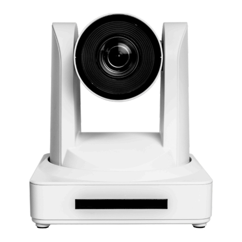
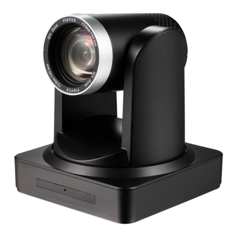
AT-HDVS-CAM
and
AT-HDVS-CAM-W
Panel Descriptions
1 2 3 4
1 RS-232 3
LAN
Connect included VISCA to RS-232
adapter here to control the camera with a
third party software
or
hardware controller. 4
2 USB
Connect USS A cable
to
this port from the
USS port
of
the AT-UHD-HDVS-300-RX.
Mounting Instructions
Connect
to
a network switch to control
the unit via TCP/IP
or
webGUI.
DC 12V
Connect the included 12Vpower supply
to
this port.
The HDVS-CAM has
two
installation options, wall mount (included) and ceiling mount (purchased
separately).
Wall Mount installation
The install the HDVS-CAM, 4 M6 swelling bolts, 1
1/4
20UNC bolt, 4 M6 nuts & shims, the
included wall mount bracket, and the HDVS-CAM are needed.
1 Install the M6 swelling bolts in a rectangular pattern on the wall, 100 mm wide and 50 mm
high.
2 Attached the wall mount bracket onto the wall,
by
placing them on the M6 swelling bolts
and securing it with the
M6
nuts and shims.
3 Once the wall mount bracket is secure on the wall, place the camera on the
top
of
the wall
mount bracket and secure it with the 1/4 20UNC bolt.
2
