Panduit OPTICAM 2 User manual

© Panduit Corp. 2017 FS132C
OPTICAM 2 QUICK SETUP GUIDE
Please register and update the OptiCam 2 Tool to the most recent
firmware available at Panduit.com > Support > Download Center >
Software/Firmware/Printers > OptiCam 2 Termination Tool.

© Panduit Corp. 2017 FS132C
Page 1 of 7
OptiCam 2 Termination Tool
Quick Setup Guide
© Panduit Corp. 2017
WARNING
Read and understand the instructions and safety information in this manual
before operating this tool.
Failure to observe this warning can result in bodily injury.
Warning: Risk of fire. Battery can explode or leak and cause injury if installed
backwards, disassembled, charged, crushed or exposed to fire or high
temperature.
CAUTION
Caution - Use of controls or adjustments or performance of procedures
other than those specified herein may result in hazardous radiation
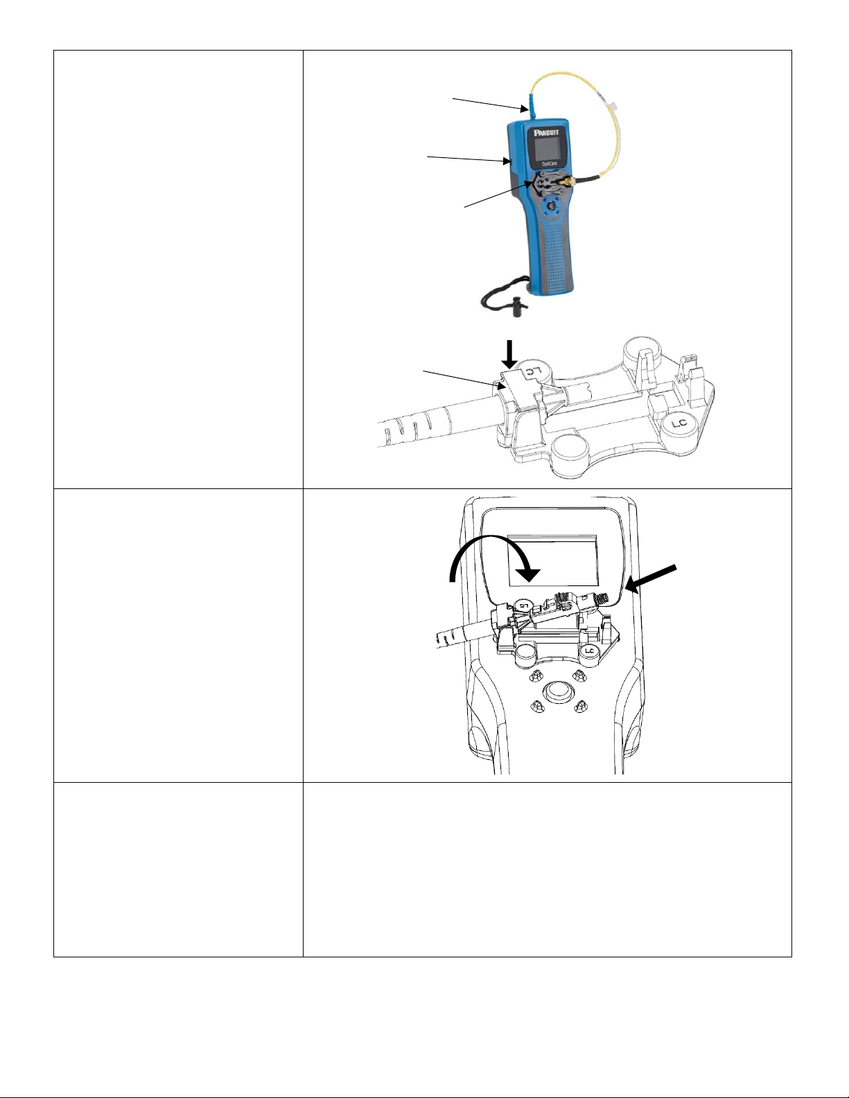
exposure. The laser is emitted from the LC connector located at the top
of the tool. See the next page illustration for connector location.
•Never point the laser into the eyes of others.
•Do Not stare directly at the laser beam.
•Do Not set up tool to work at eye level or operate the tool on a
reflective surface as the laser could be projected into your eyes or
the eyes of others.
Viewing the laser output with certain optical instruments (for example,
eye loupes, magnifiers, and microscopes) within a distance of 3.9” (99
mm) may pose an eye hazard.
Remove the batteries when storing for an extended period of time to
avoid damage to the tool should the batteries deteriorate.
TECHNICAL INFORMATION
Recommended Use: With available launch cords and cradles only
Laser Diode Type: IEC 60825-1 Class 1 Laser product
Connectors: LC, SC, ST, singlemode and multimode, Panduit
connectors only
Power Supply: 2 size AA (type L91) 1.5volt Lithium Iron Disulfide
batteries, Max Discharge: 2.5 amp continuous,
included. Size AA alkaline batteries can be used at
a reduced rate battery life.
Tool can also be powered without batteries
through the power/data (5 VDC, 1 amp max) port
on the side of the tool.
Rated Battery Life: Approximately 8 hours (continuous use)
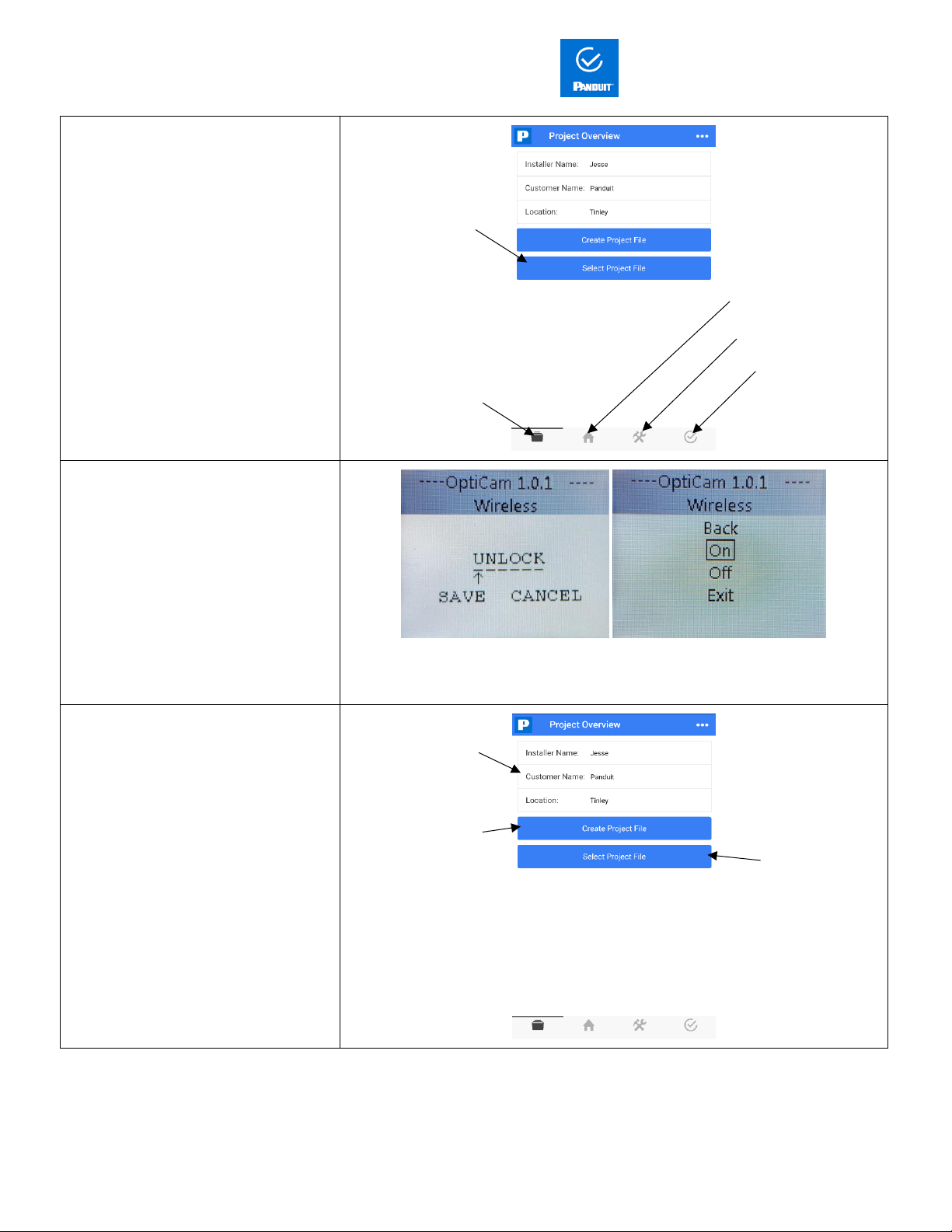
Firmware Updates: Use power/data port on the side of the tool to
connect to PC, visit www.panduit.com for latest
firmware
Environment: FOR INDOOR USE ONLY
Max altitude 2000m
Pollution degree 2
Operating Temperature: +32° F to +104° F (0° C to +40° C), <93% RH, non-
condensing
Storage Temperature: -40° F to +158°F (-40°C to +70°C)
Overall Dimensions: 2.1" H x 2.8" W x 9.1" L (53mm x 71mm x 231mm)
Weight: 9.0 oz (255 g) without batteries
Tool Storage
After all connector terminations are complete, detach the launch cord from the tool by disconnecting the LC connector at the top of the tool. Detach
the ferrule adapter from the cradle and put dust caps on both ends of the launch cord. Place tool, launch cord, and cradle in a protective case.
Care and Handling
•Laser tools are precision instruments, which should be handled with care.
•Avoid shock, vibrations, and extreme heat.
•Avoid dust and water that could obstruct laser.
•Keep tool dry and clean.
•Check batteries regularly to avoid deterioration.
•Remove batteries if the tool is to be stored for an extended period.
Tool Maintenance
•This tool contains no user serviceable parts.
•The laser output is not user adjustable.
•Contact Panduit Corp. for service needs.
Symbols
This symbol indicates the need for separate collection of electrical and electronic equipment waste.
Separating electronic waste can halt the potential adverse effects on the environment and human health as a result of the hazardous substances
in electrical and electronic equipment.
This waste should be returned to the proper collection facility.
当該機器には電波法に基づく、技術基準適合証明等を受けた 特定無線設備を装着している。
OptiCam 2

© Panduit Corp. 2017 FS132C
Page 2 of 7
Product Overview
Step 1
Install batteries into the battery
compartment, be sure to install the
batteries in the correct orientation.
Power on by using the center of the
navigation button, pressing directly
down.
Step 2
Use the navigation button to navigate to
the menus and to “Connector Type” and
select the correct connector options
Use the navigation button left and right
button to select the correct information.
The selected text will become red, “Save”
this option.
LCD display guides
user through the
termination
process
5-way joystick
navigates users
quickly through the
on-screen menus
Launch cord
removeable for
changing from
single or multimode
fiber
Self-aligning,
reversible cradle
for left or right
orientation (right
orientation shown)
Press down on the
navigation button to
power on the tool
Bluetooth Indicator
Connector,
orientation & color
change to match
selection
Next icon. The
outline indicates
this is current
selection
Back icon
Menus

© Panduit Corp. 2017 FS132C
Page 3 of 7
Step 3
Install the correct OptiCam 2 launch cord
and OptiCam 2 cradle. An LC connector
on the launch cord attaches to a port at
the top of the tool and the unique
adapter attaches it to the cradle. The
cradle attaches to the tool (singlemode
LC launch cord, and LC Cradle are shown)
with either a left or right orientation.
Step 4
A) Insert a connector while the launch
cord is tilted up to receive the connector.
B) Tilt the connector down, ensure the
connector backbone snaps in to the
cradle.
Note: Each connector has slightly
different cradle operation. Refer to the
individual connectors’ specific
instructions in the OptiCam 2
Installation Instructions FS133.
Step 5
REFER TO FIBER PREP STEPS
IN USER INSTALLATION
INSTRUCTIONS
Have fiber prepped and cleaved to 7mm
before starting the next termination
steps.
See the following Installation instructions for fiber prep steps:
FS133
LC Connector port
Left orientation for
cradle shown
Launch cord
snaps into
the cradle
Data Port
A
B

© Panduit Corp. 2017 FS132C
Page 4 of 7
Step 6
To start the connector test, select the
“Next” icon, pressing the navigation
button directly down.
The tool will perform a background test
of the connector. After passing the
background test, the “Insert Fiber”
command will display automatically.
Insert cleaved fiber and maintain gentle
forward pressure while waiting for the
“CAM & TEST” command to appear on
the screen.
When the screen displays the “CAM &
Test” command, A) Maintain gentle
forward pressure on the field fiber, and
B) ”Cam” the connector, then select the
“Next” arrow to perform test.
A
B

© Panduit Corp. 2017 FS132C
Page 5 of 7
Step 7
Validate IL value meets project
requirements.
If needed, re-test by using the “Re-test”
icon, or re-terminate using the “Back”
icon and reperform steps 5 and 6. The
OptiCam connector can be reused up to
three times.
Care and Maintenance
a. Replacing the Ferrule
Adapter
Fiber tip of the launch cords should
be cleaned every fifty (50) connector
terminations. To clean, retract the
boot to expose the cable crimp
sleeve. Remove the Ferrule Adapter
by holding the crimp sleeve and
unthreading from the Ferrule
Adapter Assembly to expose the
white ceramic split sleeve.
b. Replacing the Split Sleeve
Twist the split sleeve and pull to
remove it from the assembly,
exposing the tip of the fiber. Clean
the fiber tip by wiping along fiber
clean wipes wet with isopropyl
alcohol, wiping from wet to dry, and
replace the split sleeve.
Note: 1.25 millimeter cord is shown for reference. The process is
the same for the 2.5 millimeter cord.
Re-test icon
Back icon
Cable Crimp Sleeve
Ferrule Adapter
Ceramic Split Sleeve
Adapter Assembly
Fiber Tip
Ceramic Split Sleeve

© Panduit Corp. 2017 FS132C
Page 6 of 7
Mobile App, install from App store on your mobile device. Connect-It.
App Overview
Step 1
After performing terminations, connect
OptiCam 2 tool to the Connect-It app.
Navigate to the menus of the OptiCam 2
tool and select:
Tool Settings>Wireless>On.
Then select “Exit”.
Note: The tool name is found under
Menus>Tool Settings>Tool Name.
Rename for ease of use.
Enter the wireless password given when registering the tool at Panduit.com
Then turn wireless on.
Step 2
Create a new project in Connect-It app.
Enter Project
information
Select an
existing
project
Create a Project
Tool list
Projects Overview
Tool Settings
Test Window
Select an
existing project

© Panduit Corp. 2017 FS132C
Page 7 of 7
Step 3
Connect to the OptiCam 2 tool, pull
down to refresh the list, and select the
appropriate tool name from the list.
Step 4
The app will indicate that the tool has
un-synced records if terminations were
done on the tool without the app and
tool being synced. Select “OK” to sync
which will transfer the records of the
termination(s) to the project file in the
app.
Note: The records will no longer be
available on the OptiCam 2 tool.
Step 5
Export the connector data. Navigate to
the “Project Overview”, select the
current project, and select the “Share”
option. Your mobile device’s default
email will open with a CSV attachment
containing the connector data.
Other manuals for OPTICAM 2
1
This manual suits for next models
3
Table of contents
Other Panduit Test Equipment manuals
Popular Test Equipment manuals by other brands

GE
GE ADTS 542 instruction manual

LeCroy
LeCroy Digital Oscilloscopes Guide

Agilent Technologies
Agilent Technologies Medalist i3070 Series System installation

REMS
REMS Push instruction manual

Agilent Technologies
Agilent Technologies U1604A quick start guide

Siemens
Siemens 3VW9011-0AT40 operating instructions