1 689 989 132 2011-09-09| Robert Bosch GmbH
6 | BAT 131 | Perform Testen
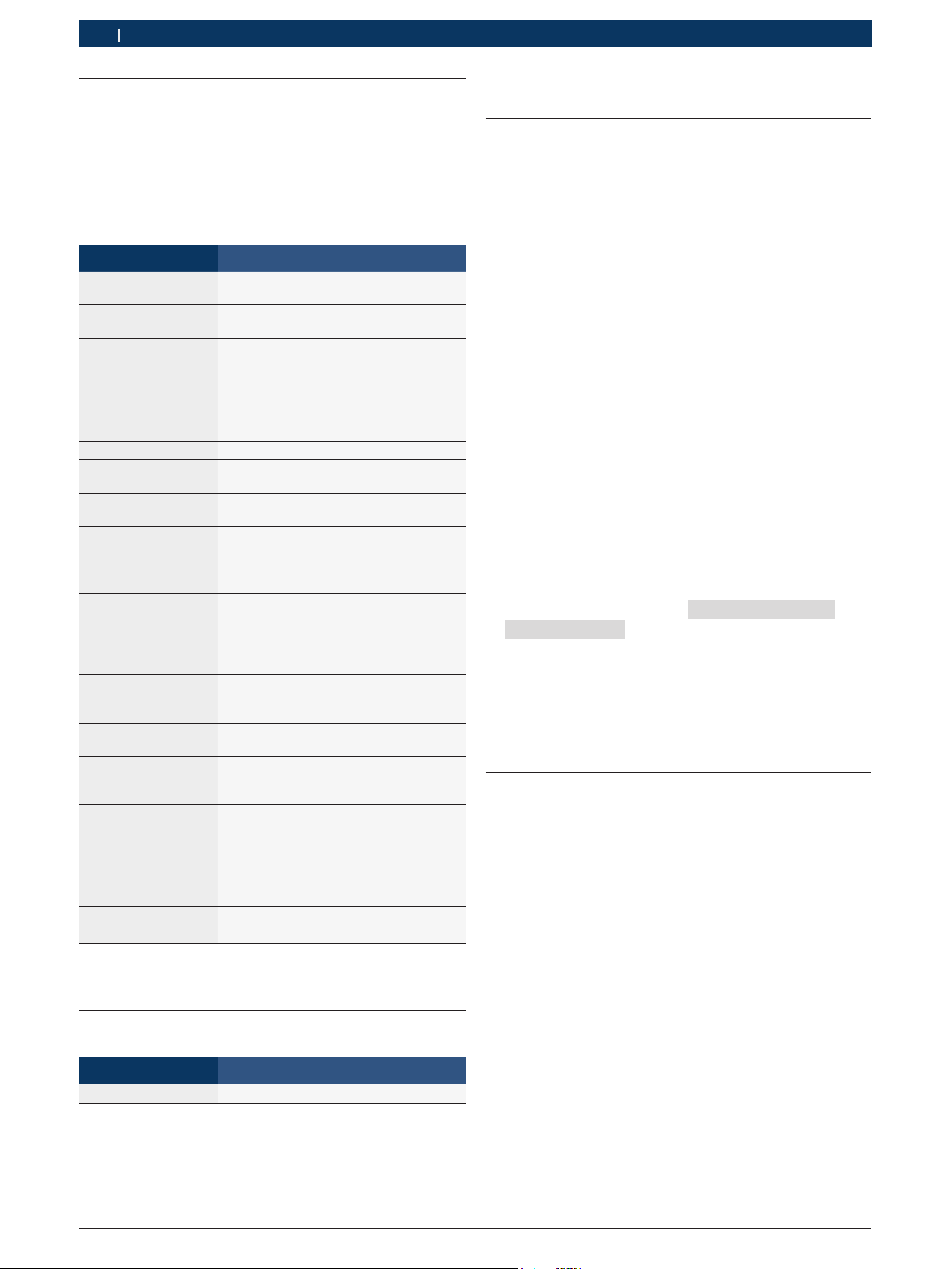
3.6 Menu
1. Press to access the Menu.
2. Use the or to highlight the line you want to
edit.
3. Press Eto edit the line or save your changes.
4. Use
or
to select the function to use or edit.
5. Press Eto move to the next location.
6. Press to return to the Menu.
Option Description
Perform Test Begin the Battery and System Test pro-
cedure.
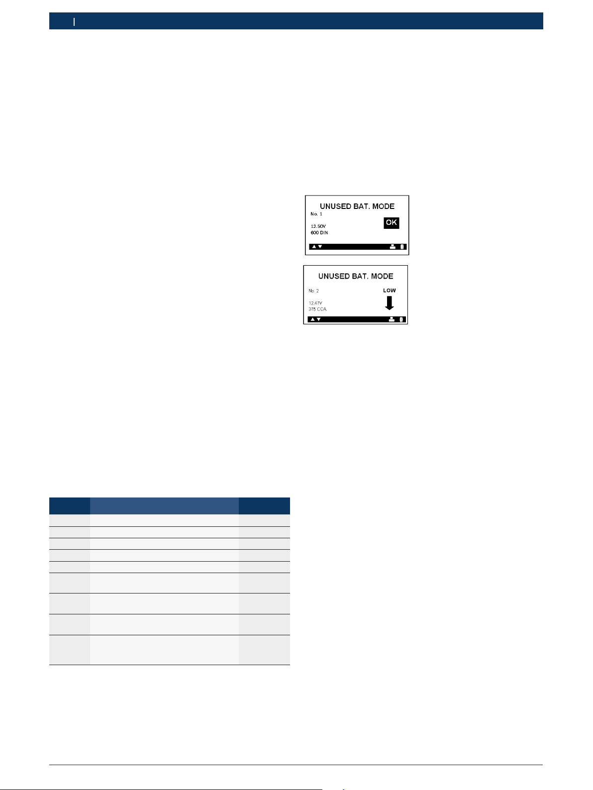
Unused Battery
Mode
Perform a quick test on batteries in in-
ventory.
ON Perform Unused Battery Test, Clear or
add to memory,
OFF Turn off "Unused Battery Mode"
View Test Results View Unused Battery Mode test results.
S/N Input Enable or disable serial number if a bad
cell is detected.
Voltmeter Start the test battery voltage.
View / Print Display the previous test result. Press
the button to print the results.
Export / Clear Data Export the last test result to a USB-type
jump drive1) or clear the tester memory.
Counter RDeletion of results.
RShows a summary of the results of
the measurements taken.
Settings Customize tool options to fit your needs.
Language Select a language for the tester.
Default: English
Set Address Create a header for your printed test re-
sults with your business location infor-
mation.
Set Time Select 24-hour or AM/PM and set the
time.
Default: AM/PM
Set Date Select the date format and date.
Default: MM/DD/YYYY
Contrast Adjust the contrast setting of the tes-
ter display.
Default: 10
Temperature Units Select the temperature units Degrees °F
or Degrees °C.
Default: Degrees F
Amp Clamp Prompt for Amp Clamp availability.
Version Info Lists the software version, software ver-
sion date, and serial number.
Update Update the tester's internal operating
software.
1) After export to an USB stick you can open the text-file with
extension ""bty" preferable with Excel.
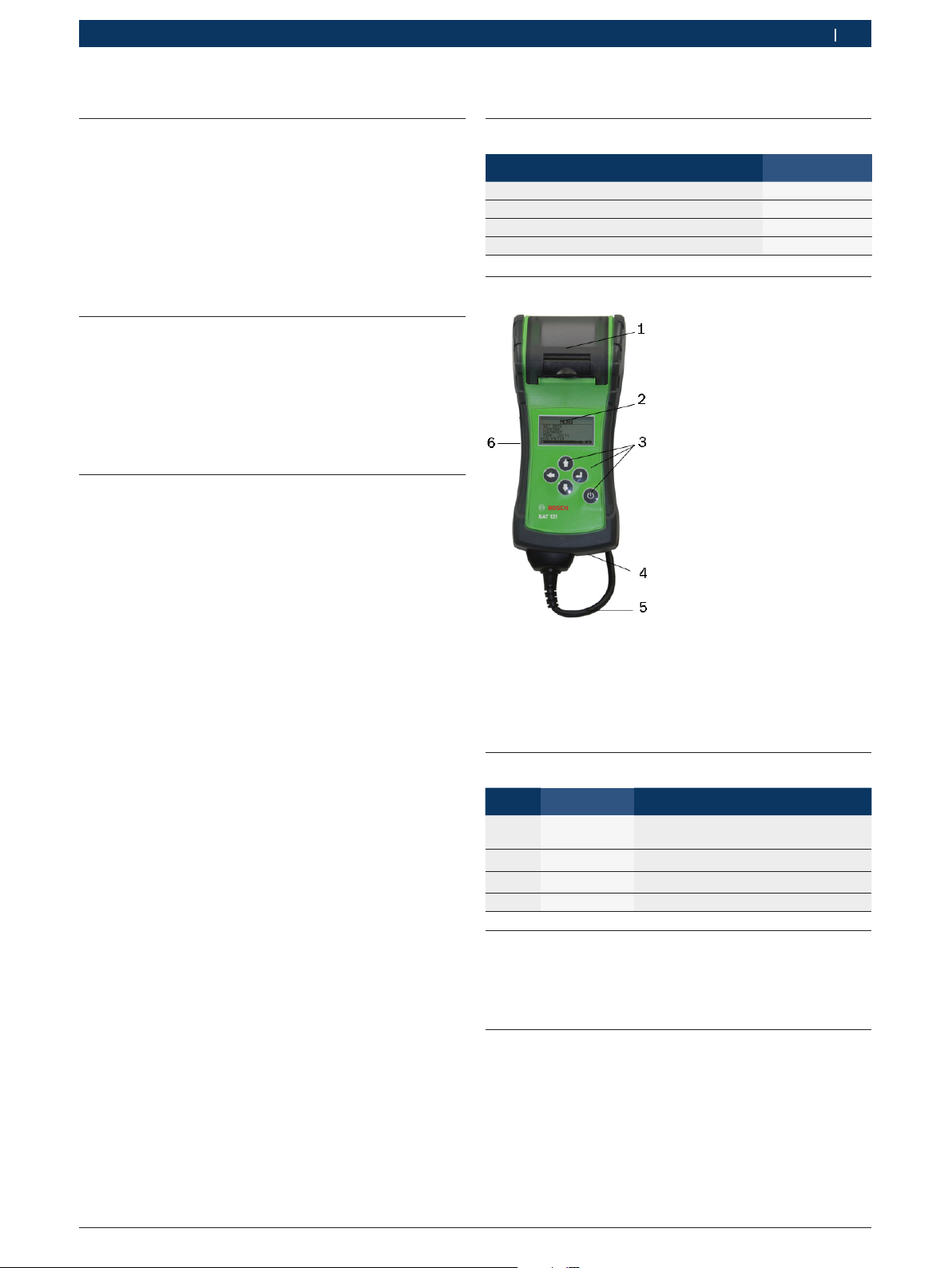
3.7 Special accessory
Designation Item number
Current probe 1 681 354 034
4. Perform Test
4.1 Test Preparations
Before connecting the tester, clean the battery posts
or side terminals with a wire brush and a mixture of
baking soda and water. When testing side-post batte-
ries, install and tighten lead terminal adapters. A set of
adapters is included with the tester.
!Do not test at or with steel bolts. Failure to install
terminal adapters or installing terminal adapters
that are worn or dirty may result in inaccurate test
results. To avoid damage, never use a wrench to
tighten the adapters more than ¼ turn.
iIf you are testing in the vehicle, make sure all acces-
sory loads are off, the key is not in the ignition, and
the doors are closed.
4.2 Connecting BAT 131
1. Connect the red clamp to the positive (+) terminal
2. Connect the black clamp to the negative (–) terminal.
!For a proper connection, rock the clamps back and
forth. The tester requires that both sides of each
clamp be firmly connected before testing. A poor
connection will produce a CHECK CONNECTION or
WIGGLE CLAMPS message. If the message appears,
clean the terminals and reconnect the clamps.
iThe preferred test position is at the battery termi-
nals. If the battery is not accessible, you may test at
the jumper post; however, the available power mea-
surement may be lower than the actual value.
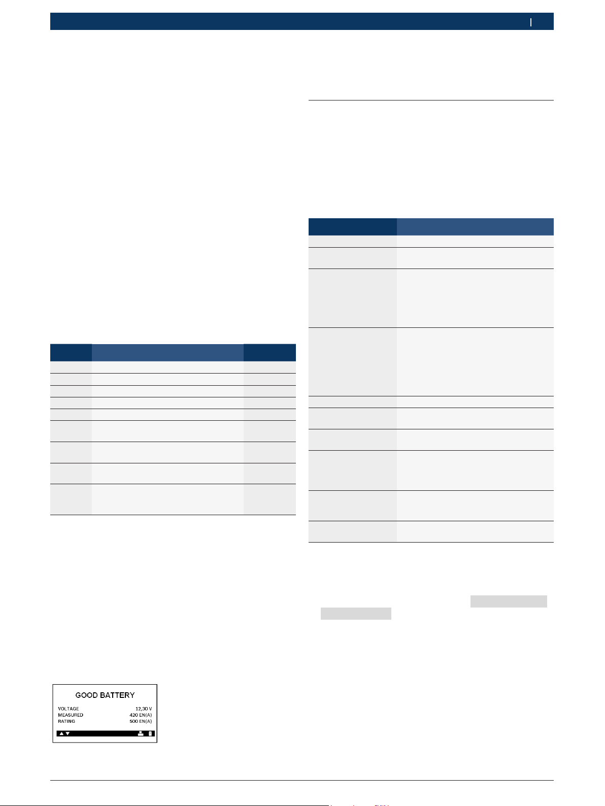
4.3 Battery Test
1. BAT. LOCATION
Scroll to and select IN VEHICLE or OUT OF VEHICLE
for a battery not connected to a vehicle.
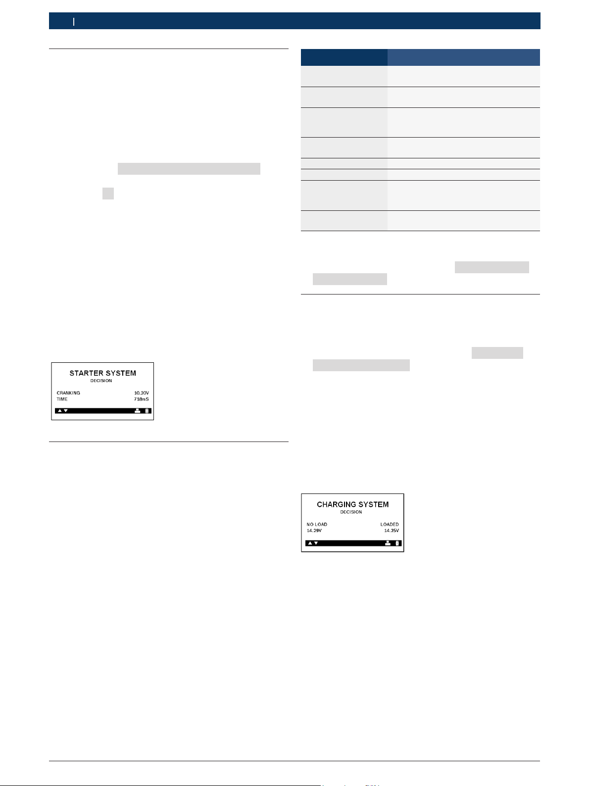
iFollowing an "IN VEHICLE" test you will be prompted
to test the starting and charging systems.
!The performance of the starting and charging sys-
tems depends on the battery’s condition. It is impor-
tant that the battery is good and fully charged before
any further system testing.