3
PART 1 – VERIFY EQUIPMENT OPERATION; cont.
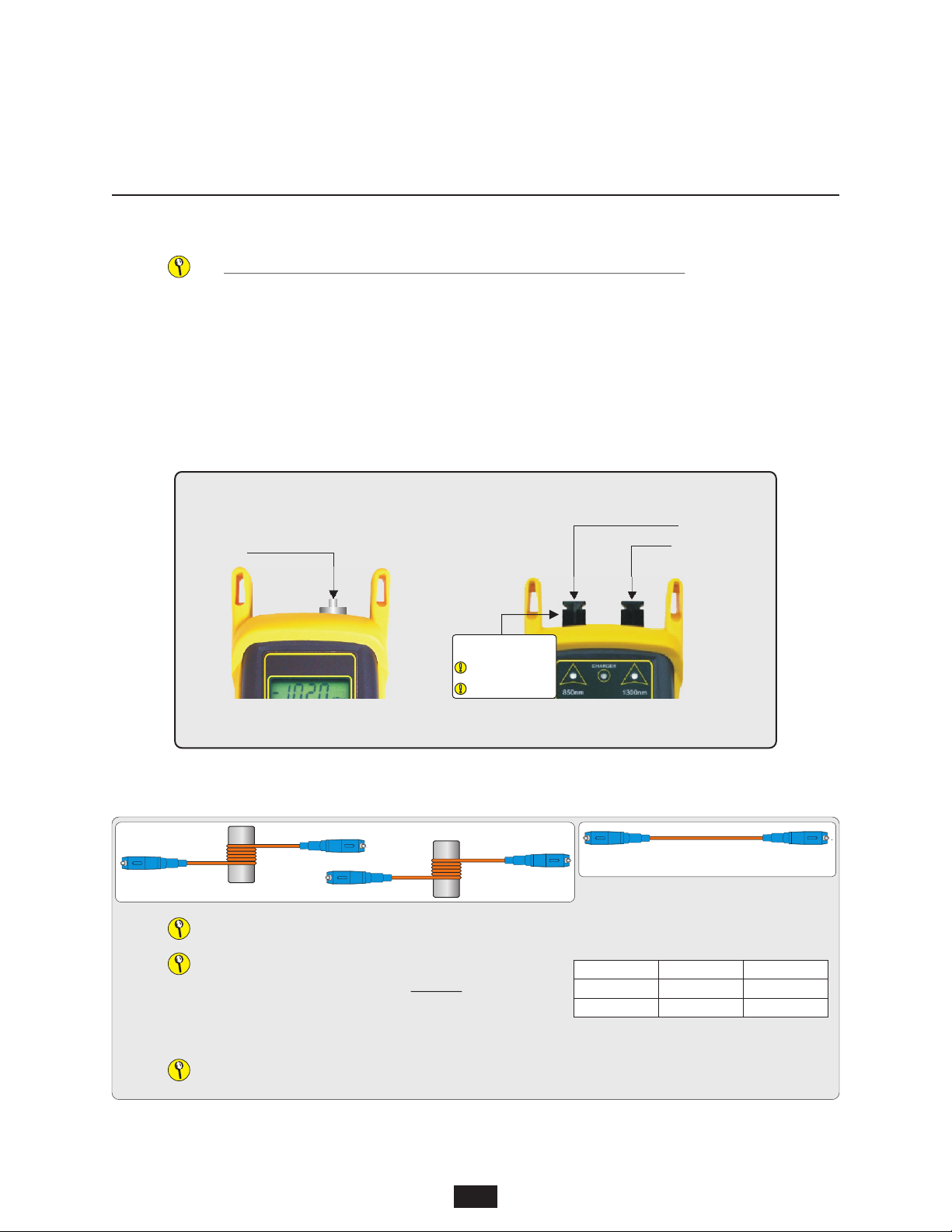
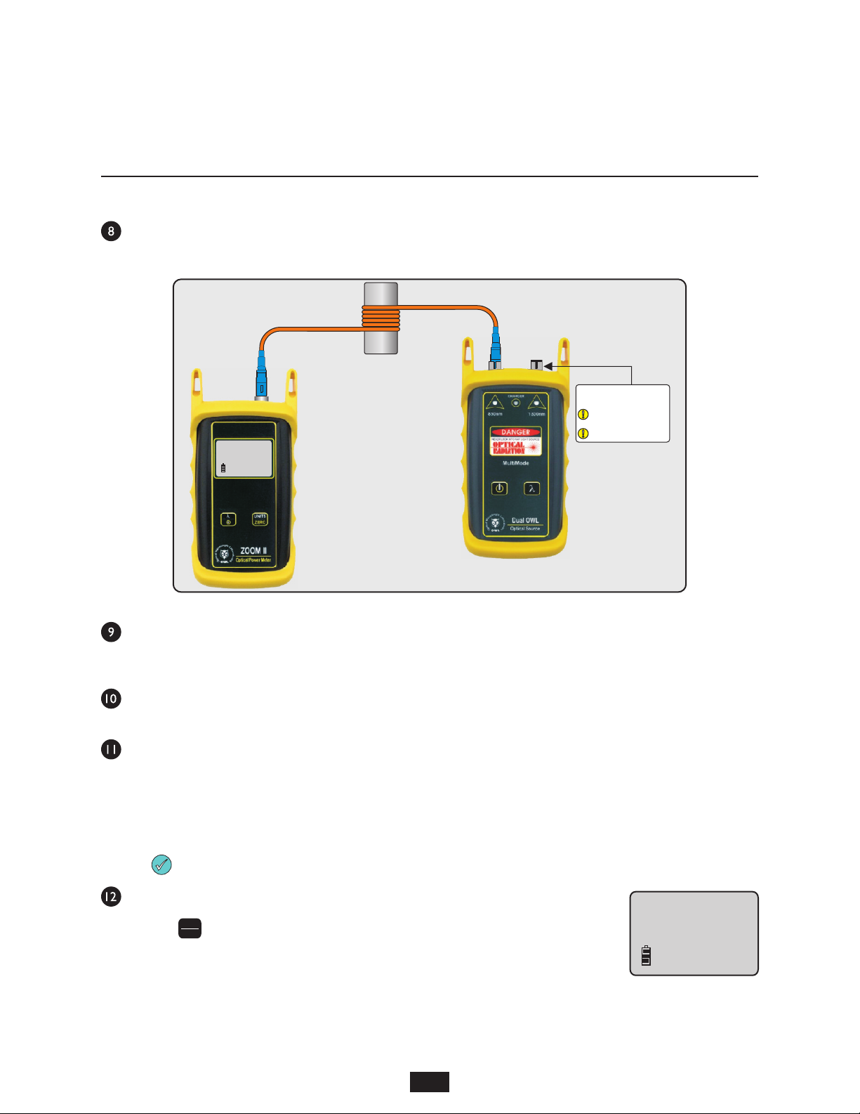
Connect a mandrel-wrapped patch cable between the detector port on the ZOOM 2 and the left-hand port (850nm) on the
Dual OWL(Figure 4).
Compare the reading on the ZOOM 2 to Table 1 for acceptable power levels. The mandrel-wrapped patch cable should be
replaced if it is below the acceptable power level. Once proper operation has been verified, remove the mandrel-wrapped
cable from the power meter and light source, then continue to the next step.
Connect a second mandrel-wrapped patch cable between the detector port on the ZOOM 2 and the left-hand port (850nm)
on the Dual OWL(Figure 4).
Compare the reading on the ZOOM 2 to Table 2 for acceptable power levels. The patch cable should be replaced if it is
below the acceptable power level. Once proper operation has been verified, leave the mandrel-wrapped patch cable
connected to the power meter and light source, then continue on to the next step.
PART 2 – SET REFERENCE
Setting a reference is commonly referred to as “zeroing”.
Ensure the power meter and light source are still connected together (Figure 4), then press and
hold on the ZOOM 2 to set the reference for 850nm.
The ZOOM 2 display should change to show readings in ‘dB’, and the power reading should be
approximately 0.00 dB. This means that the meter and light source have been successfully
“zeroed” at 850nm.
UNITS
ZERO
QUICK REFERENCE GUIDES
Optical Power Meter: ZOOM 2
Fiber Optic Light Source: DUAL OWL Series PAGE 3 OF 5
FIGURE 4
Mandrel-wrapped
cable connection
dBm
. . .20.00
-
850
nm
SC connectors shown here;
connector style may vary
LIGHT SOURCE
CONNECTOR PORTS
Do NOT insert APC connector
into either light source port
dBm
.2. .0.00
-
850
nm