PANHANS BSB 400 User manual

TRANSLATION OF THE ORIGINAL VERSION
HOKUBEMA Maschinenbau GmbH
Graf-Stauffenberg-Kaserne, Binger Str. 28 | Halle 120
DE 72488 Sigmaringen | Tel. +49 07571 755-0
E-Mail: info@hokubema-panhans.de | Web: https://hokubema-panhans.de
Operating Manual
Bandsaw Machines
PANHANS BSB 400 / 500 / 600 / 700 / 800 / 900
Machine Type:
Bandsaw Machine Series BSB 400 - 900

BA_PH_BSB-400-900_EN_44-21.docx
2
Table of Contents
1Introduction.................................................................................................................................................... 6
1.1 Legal Notice ............................................................................................................................................................ 6
1.2 Illustrations ............................................................................................................................................................. 6
2Symbols .......................................................................................................................................................... 6
2.1 General Symbols ..................................................................................................................................................... 6
2.2 Symbols in Safety Instructions ................................................................................................................................ 7
3General........................................................................................................................................................... 8
3.1 Structure of the Machine........................................................................................................................................ 8
3.2 Target Group and Previous Experience................................................................................................................... 8
3.3 Requirements for the Operators............................................................................................................................. 8
3.4 Accident Prevention................................................................................................................................................ 9
3.5 General Safety Regulations..................................................................................................................................... 9
3.6 Machine Description............................................................................................................................................... 9
3.7 About the BSB 400 - 900 Series............................................................................................................................. 10
3.8 Standard Equipment ............................................................................................................................................. 10
3.9 Available Accessories ............................................................................................................................................ 10
4Safety............................................................................................................................................................ 11
4.1 Basic Safety Instructions ....................................................................................................................................... 11
4.1.1 Application Area and Intended Use............................................................................................................. 11
4.1.2 Modifications and Conversions to the Machine.......................................................................................... 11
4.1.3 Connection to a Central Emergency Stop Switch ........................................................................................ 11
4.1.4 Residual Risks .............................................................................................................................................. 12
4.1.5 Observe the Environmental Protection Regulations ................................................................................... 13
4.1.6 Organisational Measures............................................................................................................................. 13
4.1.7 Personnel Selection and Qualification - Basic Duties .................................................................................. 14
4.2 Safety Instructions for Specific Phases of Operation ............................................................................................ 14
4.2.1 Before starting Work................................................................................................................................... 14
4.2.2 Normal Operation ....................................................................................................................................... 14
4.2.3 Special work within the Scope of Maintenance Work as well as Troubleshooting in the Workflow .......... 15
4.2.4 Safe Working Practices................................................................................................................................ 16
4.2.5 Safety Equipment ........................................................................................................................................ 16
4.2.6 Noise ........................................................................................................................................................... 16
4.3 Danger Zones on the Bandsaw ............................................................................................................................. 17
4.3.1 Danger Zone Bandsaw Blade....................................................................................................................... 17
4.3.2 Danger Zone around the Machine .............................................................................................................. 17
5Machine Data ............................................................................................................................................... 18
5.1 Series and Expandability ....................................................................................................................................... 18
5.2 Technical Specifications ........................................................................................................................................ 19
5.3 Dimensions ........................................................................................................................................................... 19
5.4 Emission Levels according to EN ISO 3746:2010................................................................................................... 20

BA_PH_BSB-400-900_EN_44-21.docx
3
5.4.1 Noise Information ....................................................................................................................................... 20
5.4.2 Noise Emission Values................................................................................................................................. 20
5.4.3 Dust Emission according to GS-HO-05 in mg/m³ air (permissible max. 2.0 mg/m³ air)............................... 20
5.4.4 Extraction .................................................................................................................................................... 20
6Installation and Connection ......................................................................................................................... 21
6.1 Check Delivery Conditions .................................................................................................................................... 21
6.2 Transport to the Installation Site .......................................................................................................................... 21
6.2.1 Transport of Models BSB 400 - 700............................................................................................................. 21
6.2.2 Transport of Models BSB 800 - 900............................................................................................................. 21
6.3 Pre-Assembly ........................................................................................................................................................ 21
6.3.1 Pre-Assembly of Models BSB 400 - 700....................................................................................................... 21
6.3.2 Pre-Assembly of Models BSB 800 and 900.................................................................................................. 21
6.4 Installing the Machine........................................................................................................................................... 22
6.5 Temporary Storage ............................................................................................................................................... 22
6.6 Lashing on a Transport Vehicle ............................................................................................................................. 22
6.6.1 Lashing Models BSB 400 / 500 / 600 ........................................................................................................... 23
6.6.2 Lashing Models BSB 700 / 800 / 900 ........................................................................................................... 23
6.7 Connecting the Extraction Unit............................................................................................................................. 24
6.8 Electrical Connections........................................................................................................................................... 25
7Components and Controls............................................................................................................................ 26
8Commissioning ............................................................................................................................................. 27
8.1 Switching ON and OFF........................................................................................................................................... 27
8.1.1 Switch on 2.2 kW Models............................................................................................................................ 27
8.1.2 Switch on 3.0 - 7.5 kW Models.................................................................................................................... 27
8.1.3 Switch on Machines with Electric Brake...................................................................................................... 28
8.1.4 Switching on with Variable Sawblade Speed Control (Option).................................................................... 29
8.2 Frequent switching ON and OFF in succession ..................................................................................................... 29
9Settings and Operation................................................................................................................................. 30
9.1 Basic Factory Setting............................................................................................................................................. 30
9.2 Door Interlock with Safety Switches ..................................................................................................................... 30
9.3 Inserting and Tensioning a Bandsaw Blade........................................................................................................... 31
9.4 Adjusting the upper Bandsaw Wheel.................................................................................................................... 32
9.5 Height adjustment of the upper Saw Blade Guide................................................................................................ 32
9.6 Swivel Table .......................................................................................................................................................... 32
9.7 APA 2 - Saw Blade Guides ..................................................................................................................................... 33
9.7.1 Structure and Components ......................................................................................................................... 33
9.7.2 Adjusting the Saw Blade Guides.................................................................................................................. 33
9.7.3 Basic Setting of the Back and Side Rollers (Overview) ................................................................................ 34
9.7.4 Conversion to Left Version .......................................................................................................................... 34
9.7.5 Saw Blade Guides - Troubleshooting........................................................................................................... 35
10 Using the Fence ............................................................................................................................................ 36

BA_PH_BSB-400-900_EN_44-21.docx
4
10.1 Convert the Fence to the Right of the Saw Blade ................................................................................................. 36
11 Replace Table Insert ..................................................................................................................................... 36
12 General Instructions for Use ........................................................................................................................ 37
12.1 Bandsaw Blades .................................................................................................................................................... 37
12.2 Use of the Machine............................................................................................................................................... 37
12.3 Completion of the Work ....................................................................................................................................... 39
13 Optional Components .................................................................................................................................. 40
13.1 Variable Sawblade Speed Control......................................................................................................................... 40
13.2 Measurement Scale on the Table ......................................................................................................................... 40
13.3 Table Swivel Device............................................................................................................................................... 40
13.4 Mitre Fence “Top”................................................................................................................................................. 41
13.5 Table Extension..................................................................................................................................................... 41
13.6 Kreisfix for Circular Cuts........................................................................................................................................ 41
13.7 Machine Moving Trolley ....................................................................................................................................... 41
13.8 Laser Cut Position Indicator (Option for BSB 600 - 900) ....................................................................................... 42
13.8.1 Special Features of Use ............................................................................................................................... 42
14 Troubleshooting ........................................................................................................................................... 43
15 Maintenance and Inspection........................................................................................................................ 45
15.1 Replace Ball Bearings ............................................................................................................................................ 45
15.2 Lubrication of the Machine................................................................................................................................... 46
15.3 Maintenance and Lubrication of the APA Saw Blade Guides................................................................................ 46
15.4 Bandsaw Roll Coating............................................................................................................................................ 46
15.5 Replacing the Bandsaw Blade ............................................................................................................................... 46
15.6 Retension the V-belt(s) ......................................................................................................................................... 47
15.7 Replacing the V-belt(s).......................................................................................................................................... 47
15.8 Readjusting the Main Motor Brake (2.2 - 3.0 kW) ................................................................................................ 48
15.8.1 Check the Adjustment................................................................................................................................. 48
15.9 Readjusting the Main Motor Brake (4.0 - 7.5 kW) ............................................................................................... 48
15.10 Models with Electric Motor Brake ........................................................................................................................ 48
16 Disassembly and Scrapping .......................................................................................................................... 49
17 Options and Accessories .............................................................................................................................. 50
17.1 BSB 400 - Bandsaw Blades .................................................................................................................................... 50
17.2 BSB 400 - Options & Accessories .......................................................................................................................... 50
17.3 BSB 500 - Bandsaw Blades .................................................................................................................................... 51
17.4 BSB 500 - Options & Accessories .......................................................................................................................... 51
17.5 BSB 600 - Bandsaw Blades .................................................................................................................................... 52
17.6 BSB 600 - Options & Accessories .......................................................................................................................... 52
17.7 BSB 700 - Bandsaw Blades .................................................................................................................................... 53
17.8 BSB 700 - Options & Accessories .......................................................................................................................... 53
17.9 BSB 800 - Bandsaw Blades .................................................................................................................................... 54
17.10 BSB 800 - Options & Accessories .......................................................................................................................... 54
17.11 BSB 900 - Bandsaw Blades .................................................................................................................................... 55
17.12 BSB 900 - Options & Accessories .......................................................................................................................... 55
EU - Declaration of Conformity ............................................................................................................................. 56

BA_PH_BSB-400-900_EN_44-21.docx
5
List of Figures
Figure 1: Bandsaw blade.................................................................................................................................................................................... 6
Figure 2: Danger zone sawblade...................................................................................................................................................................... 17
Figure 3: Danger zone around the machine..................................................................................................................................................... 17
Figure 4: Nameplate ........................................................................................................................................................................................ 18
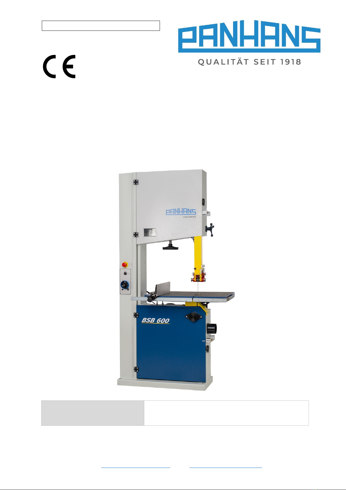
Figure 5: Series BSB 400 - 900.......................................................................................................................................................................... 18
Figure 6: Dimensions ....................................................................................................................................................................................... 19
Figure 7: Transport .......................................................................................................................................................................................... 21
Figure 8: Crane eyelet...................................................................................................................................................................................... 21
Figure 9: Attach protective cover..................................................................................................................................................................... 21
Figure 10: Lashing models BSB 400 / 500 / 600 ............................................................................................................................................... 23
Figure 11: Lashing models BSB 700 / 800 / 900 ............................................................................................................................................... 23
Figure 12: Suction nozzles................................................................................................................................................................................ 24
Figure 13: Control cabinet (option).................................................................................................................................................................. 25
Figure 14: Connections .................................................................................................................................................................................... 25
Figure 15: Components and controls............................................................................................................................................................... 26
Figure 16: Machine switch (2.2 KW) ................................................................................................................................................................ 27
Figure 17: Machine switch (3.0 - 7.5 kW)......................................................................................................................................................... 27
Figure 18: Push-switch unit (3.0 - 3.5 kW) ....................................................................................................................................................... 28
Figure 19: Push-button unit (1.1 - 1.5 kW)....................................................................................................................................................... 28
Figure 20: Push-switch unit (1.5 - 2.2 kW) ....................................................................................................................................................... 28
Figure 21: Panel with variable speed control................................................................................................................................................... 29
Figure 22: Factory adjustment points .............................................................................................................................................................. 30
Figure 23: Safety switch - door unlocked......................................................................................................................................................... 30
Figure 24: Safety switch - door locked............................................................................................................................................................. 30
Figure 25: Overview - Inserting and tensioning the bandsaw blade ................................................................................................................ 31
Figure 26: Bandsaw wheel adjustment............................................................................................................................................................ 32
Figure 27: Lever for height adjustment............................................................................................................................................................ 32
Figure 28: Adjust table inclination ................................................................................................................................................................... 32
Figure 29: APA - Structure and components.................................................................................................................................................... 33
Figure 30: Adjusting the guides........................................................................................................................................................................ 33
Figure 31: Basic adjustment of the back and side rollers................................................................................................................................. 34
Figure 32: Convert bottom guide to left .......................................................................................................................................................... 34
Figure 33: Convert top guide to left................................................................................................................................................................. 34
Figure 34: Fence in high position ..................................................................................................................................................................... 36
Figure 35: Fence turned to flat position........................................................................................................................................................... 36
Figure 36: Converting the fence for left-handers............................................................................................................................................. 36
Figure 37: Table insert ..................................................................................................................................................................................... 36
Figure 38: Table extensions and tools.............................................................................................................................................................. 38
Figure 39: Blade speed control ........................................................................................................................................................................ 40
Figure 40: Measurement scale on the table .................................................................................................................................................... 40
Figure 41: Adjust the table Inclination............................................................................................................................................................. 40
Figure 42: Mitre fence “Top” ........................................................................................................................................................................... 41
Figure 43: Table extension............................................................................................................................................................................... 41
Figure 44: Kreisfix for circular cuts................................................................................................................................................................... 41
Figure 45: Machine moving trolley .................................................................................................................................................................. 41
Figure 46: Laser device .................................................................................................................................................................................... 42
Figure 47: Laser cutting edge........................................................................................................................................................................... 42
Figure 48: Special oil 1059 ............................................................................................................................................................................... 46
Figure 49: Oil side rollers ................................................................................................................................................................................. 46
Figure 50: Oil back roller.................................................................................................................................................................................. 46
Figure 51: Retension the V-belt(s) ................................................................................................................................................................... 47
Figure 52: Replacing the V-belt(s).................................................................................................................................................................... 47
Figure 53: Readjusting the motor brake .......................................................................................................................................................... 48
Revisions:
Revision
Editor
Modification
Date
001
AG
Original manual translated
05.11.2021

BA_PH_BSB-400-900_EN_44-21.docx
6
1Introduction
This operating manual covers all bandsaw machines of the BSB 400 to 900 series.
The purpose of this document is to acquaint the user with the machine and en-
able him to use it to the full extent of its intended capabilities.
Additionally it contains important information to operate the machine safely,
properly and economically.
Observance of the manual helps to avoid hazards, reduce repair costs and down-
times and increase the reliability and service life of the machine.
Furthermore, this operating manual serves to supplement instructions based on
national regulations for accident prevention and environmental protection.
Figure 1: Bandsaw blade
These operating manual must always be available at the place of use of the machine. It must
be read and followed by every person who is assigned to work on the machine, e.g.
•during operation, including set-up, troubleshooting in the work process, removal of pro-
duction waste and maintenance,
•during maintenance (servicing, inspection, repair)
•and/or during transport.)
Apart from the operating manual and the legally binding accident prevention provisions applicable in the country
and place of use, the recognized technical regulations for safe and proper work must also be observed.
1.1 Legal Notice
All contents of these operating instructions are subject to the rights of use and copyright of HOKUBEMA Maschi-
nenbau GmbH. Any reproduction, modification, further use and publication in other electronic or printed media,
as well as their online publication, requires the prior written consent of HOKUBEMA Maschinenbau GmbH.
1.2 Illustrations
All photos, figures and graphics contained in this document are for illustration and better understanding only
and may differ from the current state of the product.
2Symbols
2.1 General Symbols
Symbol
Meaning
Indicates passages within this operating manual that must be particularly observed in order to
prevent malfunctions or damage to the machine.
Refers to chapters, sections, or figures within this document.
Refers to an external document or a third-party source.

BA_PH_BSB-400-900_EN_44-21.docx
7
2.2 Symbols in Safety Instructions
Symbol
Safety Instruction
General danger symbol, which requires the highest attention!
Failure to observe may result in damage to the equipment, serious injury or even death.
Warning of possible danger from forklift traffic!
Non-observance may result in life-threatening injuries.
Warning indicates a possible hazard under suspended loads!
Non-observance may result in life-threatening injuries.
Warning indicates a possible fall hazard!
Non-observance of these instructions may result in serious injuries.
Warning indicates a possible cutting hazard!
Risk of personal injury and possibly additional damage to equipment.
Reference to the obligation to wear protective gloves!
Non-observance of these instructions may result in personal injury.
Reference to the obligation to wear hearing protection!
Non-observance of these instructions may result in personal injury.
Reference to the obligation to wear protective goggles!
Non-observance of these instructions may result in personal injury.
Reference to the obligation to wear a respiratory protection mask!
Non-observance of these instructions may cause breathing difficulties and lung damage.
Reference to the obligation to wear safety shoes!
Non-observance of these instructions may result in personal injury.
Possible dangerous crushing hazard in the area of stationary objects!
Risk of personal injury and possibly additional equipment damage.
Reference to a possible crushing hazard!
Non-observance increases the risk of injury to hands and fingers!
This symbol warns of the dangers of electric voltage!
Failure to observe may result in damage to the equipment, serious injury or even death.
Fire hazard! Do not smoke and do not ignite open fire.
Access for unauthorized persons prohibited!
Risk of personal injury and possibly additional equipment damage.
This safety notice indicates a possible dangerous pull-in hazard!
Wearing loose clothing, jewellery as well as long untied hair is prohibited!
Risk of personal injury and possibly additional damage to property.

BA_PH_BSB-400-900_EN_44-21.docx
8
3General
This Bandsaw machine was produced by HOKUBEMA Maschinenbau GmbH according to the current state of the
art and placed on the market as a complete machine. All legal and normative regulations were observed.
3.1 Structure of the Machine
•Wheel diameter, cutting height, cutting width and blade speed vary depending on the model. The exact
values for your machine can be found in the section 5.2 “Technical Specifications”.
•The lower bandsaw wheel is driven by a three-phase motor and transmits the rotary motion to the band-
saw blade. The bandsaw wheels are provided with a wear and tear resistant lining of high durability.
•The upper bandsaw wheel is spring-mounted and can be adjusted via a hand wheel. This allows the ma-
chine to be optimally adjusted to the bandsaw blade.
•To guide the workpieces, a table fence is provided, which is mounted to the left of the saw blade.
•As protection against the saw blade and flying chips, the upper bandsaw guide is equipped with a guard.
•The control panel is used to start the bandsaw and to release the motor brake (depends on equipment).
•The height adjustment of the upper bandsaw guide and saw blade guard is done manually via a 3-arm lever
(see section 9.5).
•An emergency stop is installed in the control panel.
3.2 Target Group and Previous Experience
This operating manual is intended for the operating and maintenance personnel of the machine. The operating
personnel is to be determined by the operator and must further meet the following requirements:
•Basic technical knowledge (e.g. apprenticeship as carpenter, machine fitter, etc. and/or practice in operat-
ing woodworking machines)
•Reading and understanding these operating and maintenance instructions
In order to acquire the knowledge required to operate this machine, the operator must ensure the following
measures:
•Product training for every operator (also possible external personnel)
•Regular safety instruction
3.3 Requirements for the Operators
•The bandsaw machine may only be operated by trained personnel who have also read this manual.
•Inspection, maintenance, cleaning and repair may only be performed by technical specialists
with product-specific training and mechanical and/or electrical training.
•Specialists with product-specific training are to be commissioned and held responsible for
planning and checking the work.
•The national protective regulations for employees must be observed .
•The operator is responsible for the safe use of the machine.
•The legal minimum age must be observed.

BA_PH_BSB-400-900_EN_44-21.docx
9
3.4 Accident Prevention
To avoid accidents, the following rules must be observed for operation:
•Prevent unauthorized persons from gaining access to the machine.
•Keep unauthorized persons away from the danger areas.
•Repeatedly inform present other persons about existing residual risks (see 4.1.4).
•Conduct and record regular training & instruction for persons who must be in the area of the machine.
•New employees must be trained internally to work on a thickener and this training must be documented.
3.5 General Safety Regulations
In general, the following safety regulations and obligations apply when handling the bandsaw machine:
•The bandsaw machine may only be operated in a technically perfect and clean condition.
•It is prohibited to remove, modify or bypass any protective, safety or monitoring equipment.
•It is forbidden to modify or alter the machine without the written approval of the manufacturer / supplier.
•Faults or damage must be reported to the operator immediately, eliminated without delay and repaired if
necessary.
•For repairs, only original spare parts may be used.
•All protective, safety and monitoring devices must be regularly checked and maintained by the operator.
•Only instructed, trained or qualified persons may work on this machine.
•Maintenance work must be carried out and documented in accordance with the maintenance instruc-
tions.
•After maintenance or repair, the machine may only be started with all protective devices fitted. A respon-
sible person must be defined for this purpose, who checks that the guards have been properly installed.
•For the operation of a bandsaw machine, the respective national safety regulations for employees as well
as the national safety and accident prevention regulations apply.
3.6 Machine Description
The bandsaws of the PANHANS BSB 400 - 900 series are modern and spacious bandsaws suitable for cutting
(cross-cutting and splitting) wood and similar materials. The tool is a toothed steel band to which the cutting
movement is transmitted by two band rollers.
After actuating the main switch, the drive motor drives the lower flywheel. All operating elements as well as the
emergency stop switch are easily accessible from the machine operator's workplace.
The machine operator transfers the cutting movement to the workpiece, either manually or by means of addi-
tional auxiliary or pushing devices. The adjustable guard reduces the risk of contact with the working tool.

BA_PH_BSB-400-900_EN_44-21.docx
10
3.7 About the BSB 400 - 900 Series
Bandsaw machines of the Panhans BSB 400 - 900 series are available in different versions. They basically differ
in their sizes and wheel diameters as well as in the possible cutting heights and cutting widths. This enables them
to be individually adapted to different areas of application.
A torsion-free double-chamber welded construction forms the basis for all functional elements. Both safety doors
are secured by safety switches and can only be opened after manual unlocking. The finely planed work table
made of grey cast iron is generously dimensioned. It allows safe, precise and economical working.
The material fence is particularly stable and equipped with a practical quick-clamping device. The precise APA 2
bandsaw guide ensures optimum cutting results.
3.8 Standard Equipment
•Machine stand in torsion-free double-chamber welded steel construction
•Both doors are protected by safety switches
•Three-phase motors with different outputs from 1.1 to 5.5 kW
1
•Finely planed machine table made of cast iron
•Swivelling table up to 45°
•Replaceable table insert
•Fence ruler can be used to the left and right of the saw blade, fence profile can be folded over
•Dynamically balanced bandsaw wheels with vulcanised rubber bandages, cambered for the
use of narrow blades for curved cuts from 6 mm upwards
•1 bandsaw blade, suitable for your machine
•Blade tension indicator with viewing window for setting the recommended tension
•Upper and lower precision bandsaw guide APA 2, size 1 (BSB 400/500) and size 2 (BSB 600 - 900)
•Mechanical height adjustment of saw blade guard by hand wheel with locking pinion
•Integrated saw blade guard
•Scraper brush and chip catcher on the lower wheel
•BSB 400 - 500:
Push-button switch for start/stop with emergency stop button/motor protection relay;
wear-free, electric motor brake
•BSB 600 - 900:
From 2.2 kW with rotary cam switch with direct starting, from 3.0 kW with star-delta starting, emergency
stop switch, mechanical motor brake and motor protection relay
•Push stick with bracket on machine housing
•CE-compliant and GS-tested
3.9 Available Accessories
•Suitable saw blades, special accessories and optional components can be found in chapter 17.
•In addition, you can order the saw blades and spare parts in our online shop www.hokubema.com.
1
Depending on machine type

BA_PH_BSB-400-900_EN_44-21.docx
11
4Safety
4.1 Basic Safety Instructions
Woodworking machines can be dangerous if used improperly. Therefore, observe the safety instructions listed
in this chapter and the accident prevention regulations of your employer's liability insurance association!
The manufacturer accepts no liability for damage and malfunctions resulting from failure
to observe these operating instructions.
4.1.1 Application Area and Intended Use
The bandsaws BSB 400 - 900 are designed exclusively for cutting (coping and splitting) ma-
terials for which the respective bandsaw blade used is suitable (e.g. wood or other materi-
als with the same physical and technical properties).
This machine is not suitable for working on metal or scrap wood - which could contain nails,
screws and other metal parts.
The machine may only be operated on a level, firm surface with a sufficiently high minimum
load corresponding to the weight of the machine (refer to section
5.2).
Other materials such as cork, rubber, hard plastics, bones, etc. can also be processed. Check whether the saw
blade used is suitable for cutting these materials. Cutting these materials may require special safety measures,
even if there is no obvious danger.
Any processing of other materials requires prior consultation with the manufacturer and his approval.
Improper use can lead to danger to persons and to a defect or damage to the machine.
Only lades recommended by the manufacturer are permitted.
The machine is not suitable for operation outdoors or in potentially explosive environments.
•Permissible ambient temperature: - 15 …+40° C
•Permissible humidity: 30 …90 %
Intended use also includes connecting the machine to an adequately dimensioned extraction system and observ-
ing the operating, maintenance and servicing conditions specified in the operating manual. Any other use is con-
sidered improper and is prohibited.
4.1.2 Modifications and Conversions to the Machine
Unauthorised conversions and modifications to the machine are strictly prohibited for safety
reasons. This will invalidate the CE declaration of conformity! The manufacturer is not liable
for any resulting damage. The risk for this is borne exclusively by the operator/user.
4.1.3 Connection to a Central Emergency Stop Switch
In workshops where the bandsaw is to be connected to a central emergency stop switch (e.g. school facilities), it
should be noted that bandsaw models with electric motor brake are not suitable for this purpose. If an emer-
gency release is triggered externally, the motor brake is no longer supplied with power. Therefore, the bandsaw
blade continues to run unbraked until it comes to a standstill.

BA_PH_BSB-400-900_EN_44-21.docx
12
4.1.4 Residual Risks
The machine is built according to the latest state of the art and the recognised safety rules. Nevertheless, the
use of the machine may cause danger to life and limb of the user or third parties or damage to the machine and
other equipment. Due to the construction of the machine, the following residual risks can occur even when used
as intended and despite compliance with all relevant safety regulations:
Reading and applying the operating manual is mandatory for the operating personnel.
Be alert to possible crushing hazards:
a) when transporting the machine by forklift truck →between forks & pallet / machine
b) when picking up the machine →between machine / pallet and floor
c) when lowering the machine →between machine and fixed equipment
Be alert to possible crushing hazards when lowering the machine (from the cargo pallet to the
floor) with a forklift truck or overhead crane.
Make sure that no objects fall from the forklift truck / crane.
Do not leave any objects / tools on the machine.
It is strictly prohibited to ride on the machine during a lifting operation (with the indoor crane or
forklift). There is a danger of falling!
Unauthorised persons are not allowed to enter the installation area of the machine
(responsibility of the operator).
Be aware of possible tripping and slipping hazards on the floor. Prevent possible hazards by keep-
ing the floor dry and clean and by using anti-slip floor coverings around the machine.
Be aware of the danger from falling objects such as workpieces, tools or similar. Therefore, wear
safety shoes, especially when transporting and setting down the machine.
Pay attention to the existing danger of being cut by the bandsaw blade. Never reach into the run-
ning bandsaw blade! Use pushing devices for short and thin workpieces. Wear protective gloves
when changing the saw blade.
Be aware of the danger of snow from chips and splinters and never remove them from the danger
area by hand. Use suitable aids, e.g. hand brushes.
Danger of cutting and drawing in! Do not clean the bandsaw blade or bandsaw roller with a brush
or scraper held in your hand while the machine is running.
Danger of cutting and drawing in! In case of a broken bandsaw blade or belt, wait until the machine
has come to a complete standstill and only then open the separating safety device.
Be aware of a possible danger of being drawn in by moving machine parts or tools. This can cause
pieces of clothing or hair to be caught. Always wear tight-fitting clothing and a hair net if necessary.
Generally avoid jewellery, loose clothing and untied long hair.
Danger from electric shock! There are hazards when working on the electrical system.
This work must only be carried out by qualified personnel!
Danger from electric shock! It is strictly forbidden to bypass safety devices (e.g. safety switches).
Electrical equipment must be maintained and cleaned regularly.
Pay attention to the danger of crushing on workpiece guides and moving machine parts.
Make sure that no unauthorised persons are in the area of the machine.
Be aware of the risk of injury from flying tool parts in the event of tool breakage.
Therefore wear protective goggles.
Be aware of the risk of injury from flying workpiece parts and chips, splinters and dust coming out
of the machine. Therefore wear protective goggles.
Be aware of the increased noise emission and wear hearing protection.
Be aware of the increased dust generation. Use the extraction system and wear a dust mask if
necessary.

BA_PH_BSB-400-900_EN_44-21.docx
13
The emergency stop buttons must always be freely accessible. They must not be moved, e.g. with
hopper boxes. Check the function of the emergency stop buttons daily (before starting work).
Laser warning: The machine can be optionally equipped with a laser cut position indicator.
Looking directly into the laser beam will cause serious eye injury!
Fire hazard due to wood dust in connection with flying sparks and/or open fire!
4.1.5 Observe the Environmental Protection Regulations
During all work with the machine, the environmental protection regulations, obligations and laws for waste
avoidance and proper recycling and/or disposal applicable at the place of use must be observed. This applies in
particular to installation, repair and maintenance work involving substances that could pollute the groundwater
(e.g. hydraulic oils and cleaning agents and liquids containing solvents). In any case, prevent them from seeping
into the ground or entering the sewage system.
Store and transport the above-mentioned hazardous substances only in suitable con-
tainers. Avoid leakage of hazardous substances by using suitable collection contain-
ers. Ensure that the above-mentioned substances are disposed of by a qualified dis-
posal company.
4.1.6 Organisational Measures
Always keep this operating manual within easy reach and at the place of use of the machine.
In addition to the operating manual, observe and instruct on generally applicable legal and other binding
regulations for accident prevention and environmental protection.
Supplement the operating manual with further instructions, including supervisory and reporting duties, to
take account of special operational features (e.g. with regard to work organisation, work processes, per-
sonnel employed).
Before starting work on the machine, the person responsible for its operation must have read the operat-
ing instructions, especially the chapter "Safety Instructions". This applies in particular to personnel who
only occasionally work on the machine.
Check that work is carried out in a safety-conscious and hazard-conscious manner and in compliance with
the operating manual.
Operators must not wear open long hair, loose clothing or jewellery (including rings). There is a risk of in-
jury, e.g. by getting caught or drawn in.
Observe the safety instructions and danger warnings on the machine and keep them complete and in legi-
ble condition.
In case of safety-relevant changes to the machine or its operating behaviour, shut down the entire system
immediately and report the fault to the responsible office/person.
Use personal protective equipment as necessary or required by regulations.
Do not make any modifications, additional attachments or conversions to the machine without the manu-
facturer's approval! This will compromise safety and invalidate the manufacturer's warranty and any liabil-
ity claim. The same also applies to the installation and adjustment of safety devices and valves and to
welding work on load-bearing part.
Spare parts must meet the technical requirements specified by the manufacturer. The exclusive use of
original spare parts ensures this. Therefore, only use original spare parts from the manufacturer.
Observe the fire alarm and firefighting possibilities. Make the location and operation of fire extinguishers
(fire class ABC) known. Do not use water!

BA_PH_BSB-400-900_EN_44-21.docx
14
4.1.7 Personnel Selection and Qualification - Basic Duties
The machine design and operation is intended for right-handers.
Work on and with the machine may only be carried out by reliable personnel.
Observe the legal minimum age!
Only use trained or instructed personnel. Clearly define the responsibilities of the personnel for operating,
setting up, maintaining and repairing!
Ensure that only authorised personnel work on the machine!
If personnel to be trained or apprenticed have to work on the machine, this may only be done under the
constant supervision of an experienced resp. qualified person.
Work on the electrical equipment of the machine may only be carried out by a qualified electrician or by
untrained persons under the direction and supervision of a qualified electrician in accordance with the
electrotechnical regulations.
4.2 Safety Instructions for Specific Phases of Operation
Defects and damage to the machine are to be reported immediately after detection.
Any mode of operation that compromises safety is prohibited!
Sufficient lighting (at least 500 lux) around the machine must be ensured!
4.2.1 Before starting Work
Only use sharp, crack-free and sufficiently set bandsaw blades.
Check that the saw blade is correctly aligned on the bandsaw roll.
Check bandsaw guide for correct adjustment (back roller, lateral guide rollers).
Adjust saw blade guard to workpiece height.
Make sure that the cut for the saw blade in the table insert is as narrow as possible.
Keep the necessary aids (e.g. table fence, push stick, push-block, support bracket etc.)
ready and use them if necessary.
Keep the floor in the movement area around the machine free of tripping hazards.
Provide containers for waste.
Wear close-fitting clothing.
Wear safety shoes and ear protection.
Wear protective gloves when changing the bandsaw blade.
If gloves are required when handling workpieces, they must be fingerless.
4.2.2 Normal Operation
Guards: Take measures to ensure that the machine can only be operated in a safe and functional condi-
tion. Only operate the machine when all guards and safety-related devices such as
- detachable guards,
- emergency stop units,
- noise insulations,
- extraction system
are available and functional.
Workpiece: Before the operation, check the workpiece for
- foreign inclusions
- knots
- twists (contortions) and other irregularities.

BA_PH_BSB-400-900_EN_44-21.docx
15
Machine condition: Check the machine for externally visible damage and defects at least once per shift!
Any changes that have occurred (including those in the operating behaviour) must be reported immedi-
ately to the responsible office or person! If necessary, stop and secure the machine immediately!
Extraction: The machine must be connected to an effective extraction system. This requires a flow velocity
of at least 20 m/s for dry chips and 28 m/s for moist chips (moist 18% or more).
Work area: An obstacle-free work area around the machine is essential for safe operation. The floor
should be level, well maintained and free from debris such as chips and cut-off workpieces.
Cutting area during operation: Never try to remove splinters, chips or other parts from the cutting area
while the machine is running! Never remove splinters and chips by hand!
Special tools: For certain operating phases and operations it is necessary to use special tools for workpiece
feeding (e.g. table fence, push stick, push-block, support bracket etc.).
•When cutting upright workpieces, secure them against tilting, e.g. by means
of a stop bracket, table fence, push-block.
•Secure round workpieces with wedge support or similar against twisting.
•For very short or narrow workpieces use a suitable pushing device.
•Ensure good workpiece support for long or wide workpieces, e.g. with a table extension.
•Do not machine unshaped workpieces that do not fit on the machine table.
Work interruptions: Switch off the machine even during short interruptions! Never leave the machine
running unattended!
When the work is finished: Release the saw blade tension and provide the machine with a warning sign.
Lower the saw blade guard to table height.
Leaving the machine: Switch off the control voltage and main switch before leaving the machine. Never
leave the machine unattended in an unsecured state.
Behaviour in the event of a saw blade breakage: Be sure to wait until all bandsaw wheels have come to a
complete standstill before taking any further action. Only the lower wheel is equipped with a brake!
4.2.3 Special work within the Scope of Maintenance Work as well as Troubleshooting in
the Workflow
Observe maintenance and inspection activities prescribed in the operating manual!
These activities, as well as all other repair work, may only be carried out by qualified personnel!
For all work concerning operation, production adjustment, conversion or setting of the machine and its
safety-related equipment as well as maintenance and repair, observe switch-on and switch-off procedures
according to the operating manual and instructions for maintenance work!
Secure the machine against unexpected restarting during maintenance and repair work.
•Lock the main switch with a padlock!
Always tighten screw connections that have been loosened during maintenance and repair work!
If it is necessary to dismantle safety equipment during set-up, maintenance and repair, the safety equip-
ment must be reassembled and checked immediately after completion of the maintenance and repair
work!
Ensure safe and environmentally friendly disposal of operating and auxiliary materials (e.g. oils) and re-
placement parts (e.g. electronic components)! Refer to chapter 16 “Disassembly and Scrapping”.

BA_PH_BSB-400-900_EN_44-21.docx
16
4.2.4 Safe Working Practices
Whenever possible, a push stick or a comparable aid must be used to feed the workpiece. It is essential to
avoid working with the hands near the saw blade.
When cutting narrow workpieces, generally use a push stick.
Use aids such as auxiliary fence and push handle for concealed cuts.
Use an aluminium profile rail with a narrow contact edge for cutting narrow and low laths.
Always work with all protective devices! These must be in the intended places and in perfect working or-
der. Defective guards must be replaced immediately.
Damaged table inserts are to be replaced with new ones.
Regular maintenance and cleaning of bandsaw blades, extraction system, etc. is required to reduce noise.
Refit removed guards in accordance with the manufacturer's instructions.
Never clean the bandsaw blade or bandsaw wheels with a hand-held brush or scraper while the bandsaw
blade is in motion.
Do not start cutting until the bandsaw blade has reached full speed.
Do not use damaged bandsaw blades.
Check the bandsaw blades regularly for damage.
Replace damaged bandsaw blades immediately.
Only use bandsaw blades suitable for the operation and the material to be processed.
Do not exceed the permissible speed of the bandsaw blade.
Do not use damaged tools.
Damaged parts must be replaced with new ones.
Repairs may only be carried out by qualified personnel with the main switch locked.
The machine is equipped with an automatic motor brake. If the brake no longer brakes within the pre-
scribed braking time (10 s) despite readjustment, the customer service must be informed.
4.2.5 Safety Equipment
The machine is equipped with the following necessary safety devices:
•Complete protection of the saw blade along its entire length.
•The saw blade guard is manually height-adjustable and covers the saw blade from all four sides, preventing
hands from entering the danger zone.
•When the doors / guards are opened, the power supply to the motor is automatically interrupted.
•Additional safety switches prevent unintentional opening of the doors. In order to be able to open the doors
during a belt or wheel change, the safety switches must first be manually unlocked (see section 9.2).
•The bandsaw guide is equipped with a transparent protective cover to ensure a clear view of the cutting
area for the operating personnel. At the same time it partly serves as splinter protection.
•The standard version of the bandsaw machine is equipped with an automatic motor brake that brings the
saw blade to a standstill within 10 seconds in the event of a power interruption.
•The blade tension indicator shows the correct tension of the blade in relation to its width.
•The machine is equipped with an emergency stop switch on the control panel.
4.2.6 Noise
Certain instructions must be followed to avoid an increase in the noise level:
•Sawdust falling between the wheel and the saw blade can cause vibrations that can increase the noise level.
•Only original saw blades with a correct and clean weld must be used.
•The saw blade must be correctly adjusted for the intended work and suitable for the material.
•The instructions for the wheel surfaces (section 15.4) and the saw blade (see section 15.5) must be
followed to keep the parts in good condition and reduce the noise level.

BA_PH_BSB-400-900_EN_44-21.docx
17
4.3 Danger Zones on the Bandsaw
4.3.1 Danger Zone Bandsaw Blade
Figure 2: Danger zone sawblade
•The area 120 mm around the saw blade is a
danger zone.
•Make sure that your hands are at least 10 cm
away from the saw blade.
•If a minimum distance of 10 cm cannot be
maintained, use a push stick or other suitable
aid for feeding the workpiece.
•When feeding the workpiece, place your hands
flat with your thumbs on them and do not
spread your fingers.
•Lower the guard to a distance of max. 5 mm
from the workpiece.
Danger of cutting and being drawn in! Danger zone of 120 mm around the saw blade!
4.3.2 Danger Zone around the Machine
Another danger zone is located to the right of the machine. Here there is a particular risk of serious injury from
a torn bandsaw blade, which can be ejected in this area. During operation, it is strictly forbidden for the operator
as well as any helpers and possible observers to stay in this area!
Figure 3: Danger zone around the machine
•The operator of the machine must generally
stand in the direction of cutting, in front of the
bandsaw and outside the danger zone.
•A required helper for workpiece removal must
generally stand opposite the cutting direction
and outside the danger zone, behind the ma-
chine, on the opposite side to the operator.
•Any observers must stand in a semicircle outside
the danger zone. An adequate distance must be
kept so that the operator of the machine and a
possible helper are not hindered in their work.
Be aware of the danger posed by an ejecting bandsaw blade in the event of a band break!
Entering the danger zone during operation can lead to very serious injuries.
Only use bandsaw blades that are in perfect condition resp. have been correctly welded, ground
and set. Damaged bandsaw blades must be replaced immediately.
Danger Zone
Danger Zone
Operator
Helper
Observers

BA_PH_BSB-400-900_EN_44-21.docx
18
5Machine Data
5.1 Series and Expandability
Nameplate:
Figure 4: Nameplate
Manufacturer:
HOKUBEMA Maschinenbau GmbH
Graf-Stauffenberg-Kaserne
Binger Str. 28 | Halle 120
DE-72488 Sigmaringen (Germany)
Tel.: +49 (0) 7571 / 755-0
Fax: +49 (0) 7571 / 755-2 22
Series:
Figure 5: Series BSB 400 - 900
Expandability:
The machine is designed for the later expansion of op-
tional accessories (see chapter 17) from the extensive
manufacturer's range. If you wish to expand your machine
at a later date, please ask us for documentation on the de-
sired accessories.
Please indicate the following data:
1. Type
2. Machine-No.
3. Voltage (V)
4. Power (kW)
5. Year of manufacture
BSB 400 BSB 500 BSB 600
BSB 700 BSB 800 BSB 900

BA_PH_BSB-400-900_EN_44-21.docx
19
5.2 Technical Specifications
Position
Einheit
BSB 400
BSB 500
BSB 600
BSB 700
BSB 800
BSB 900
Bandsaw wheels
mm
400
500
600
700
800
900
Main motor
KW
1.1
1.5
2.2
3
4
5.5
PS
1.5
2
3
4
5.5
7.5
Motor brake
-
electrical
electrical2
mechanical3
mechanical3
mechanical3
mechanical3
Nominal saw blade speed
m/min
1400
1300
1550
1570
1800
1720
Max. cutting height
mm
205
330
400
420
520
540
Max. cutting width
mm
385
480
580
680
780
880
Max. saw blade length
mm
3330
4140
4735
5140
5775
6260
Min. saw blade length
mm
3230
4060
4660
5020
5670
6160
Saw blade thickness
mm
0.4
0.4 - 0.5
0.5 - 0.6
0.6 - 0.7
0.7 - 0.8
0.8 - 0.9
Wheel surface width
mm
25
30
30
35
45
47
Max. saw blade width
mm
20
25
30
35
40
40
Min. saw blade width
mm
15
15
15
15
15
15
Min. blade width with
specific crowned wheel
mm
6
6
8
8
10
10
Size saw blade guide
-
1
1
2
2
2
2
Table dimensions
mm
420 x 570
495 x 670
590 x 810
695 x 990
760 x 1145
835 x 1280
Weight
kg
130
220
280
430
550
700
For special applications, the machines can also be supplied with more powerful engines. The nameplate of the
machine (see Figure 4) shows the motor power (kW / hp), the voltage (V), the current consumption (A) and
the frequency (Hz). If you have any questions, please contact our customer service.
5.3 Dimensions
Height x length x width x table height in mm:
Modell
H
L
W
T
BSB 400
1740
760
490
900
BSB 500
1930
930
550
900
BSB 600
2120
1130
640
920
BSB 700
2275
1260
700
920
BSB 800
2475
1450
900
930
BSB 900
2650
1590
1010
1015
Dimensions and construction subject to change
Space requirement:
The effective space requirement usually de-
pends on the dimensions of the machine and
the dimensions of the workpieces to be pro-
cessed. In general, provide sufficient space
around the machine and also calculate the re-
quired workplace for the operating personnel
and for the infeed and outfeed of the work-
pieces.
Figure 6: Dimensions
2
Mechanical brake on a BSB 500 model with optional 2.2 kW motor.
3
Electric, wear-free brake with option “Variable Bandsaw Speed Control”.
LW
H
T

BA_PH_BSB-400-900_EN_44-21.docx
20
5.4 Emission Levels according to EN ISO 3746:2010
5.4.1 Noise Information
The values given are emission levels and therefore do not necessarily represent safe workplace values. Alt-
hough there is a correlation between emission and immission levels, it cannot be reliably deduced whether ad-
ditional precautionary measures are necessary or not.
Factors that may affect the current immission level at the workplace include the duration of exposure, the na-
ture of the workspace, other noise sources, etc., e.g. the number of machines and other activities in the vicin-
ity. The permissible workplace values can also vary from country to country.
However, this information should enable the user to make a better assessment of hazard and risk.
5.4.2 Noise Emission Values
Bandsaw Model
Unit
BSB 400
BSB 500
BSB 600
BSB 700
BSB 800
BSB 900
Noise level
Idle
dB(A)
80
80
80
85
85
85
Working
dB(A)
102
102
102
97
97
97
Emission pressure level at the workplace
Idle
dB(A)
67
67
67
68
68
68
Working
dB(A)
89
89
89
89
89
89
Note: When checking the accuracy of the specified emission values, the measurements must be carried out using
the same measurement method and the same operating conditions as those specified.
Uncertainty allowance K = 4 dB(A).
The workplace-related noise emission values of the machine exceed 85 dB(A)!
Therefore, suitable hearing protection must be provided to the personnel!
Note: Regular maintenance and cleaning of the bandsaw blade and extraction system as well as lubrication of
the bandsaw blade guides (back and side rollers, see section 15.2) generally has a positive effect on the ma-
chine's noise level
5.4.3 Dust Emission according to GS-HO-05 in mg/m³ air (permissible max. 2.0 mg/m³ air)
Bandsaw Model
BSB 400
BSB 500
BSB 600
BSB 700
BSB 800
BSB 900
At the workplace
0.23
0.44
0.74
0.39
0.90
0.75
5.4.4 Extraction
Bandsaw Model
Unit
BSB 400
BSB 500
BSB 600
BSB 700
BSB 800
BSB 900
Number of suction nozzles
pcs.
2
2
2
2
2
2
Suction nozzle Ø
mm
100
100
100
120
120
120
Stat. negative pressure
top/bottom
Pa
800 / 700
720 / 680
640 / 620
390 / 270
390 / 270
390 / 270
Volume flow
m³/h
790
790
790
1140
1140
1140
To ensure that the chips extracted at the point of origin and the dust are transported on to the collection system,
the conveying speed of the extracted air must be 20 m/s for dry chips and 28 m/s for moist chips (moisture 18%
or more).
This manual suits for next models
5
Table of contents
Other PANHANS Saw manuals
Popular Saw manuals by other brands

Bomar
Bomar transverse 610.440 GANC operating instructions

EINHELL
EINHELL TC-TS 2025/1 U Original operating instructions

Worx
Worx WU433 user manual

Denzel
Denzel CS-165 user manual

Parkside
Parkside PKS 1500 A2 Operating and safety instructions

Scheppach
Scheppach DECO SL Translation of original instruction manual