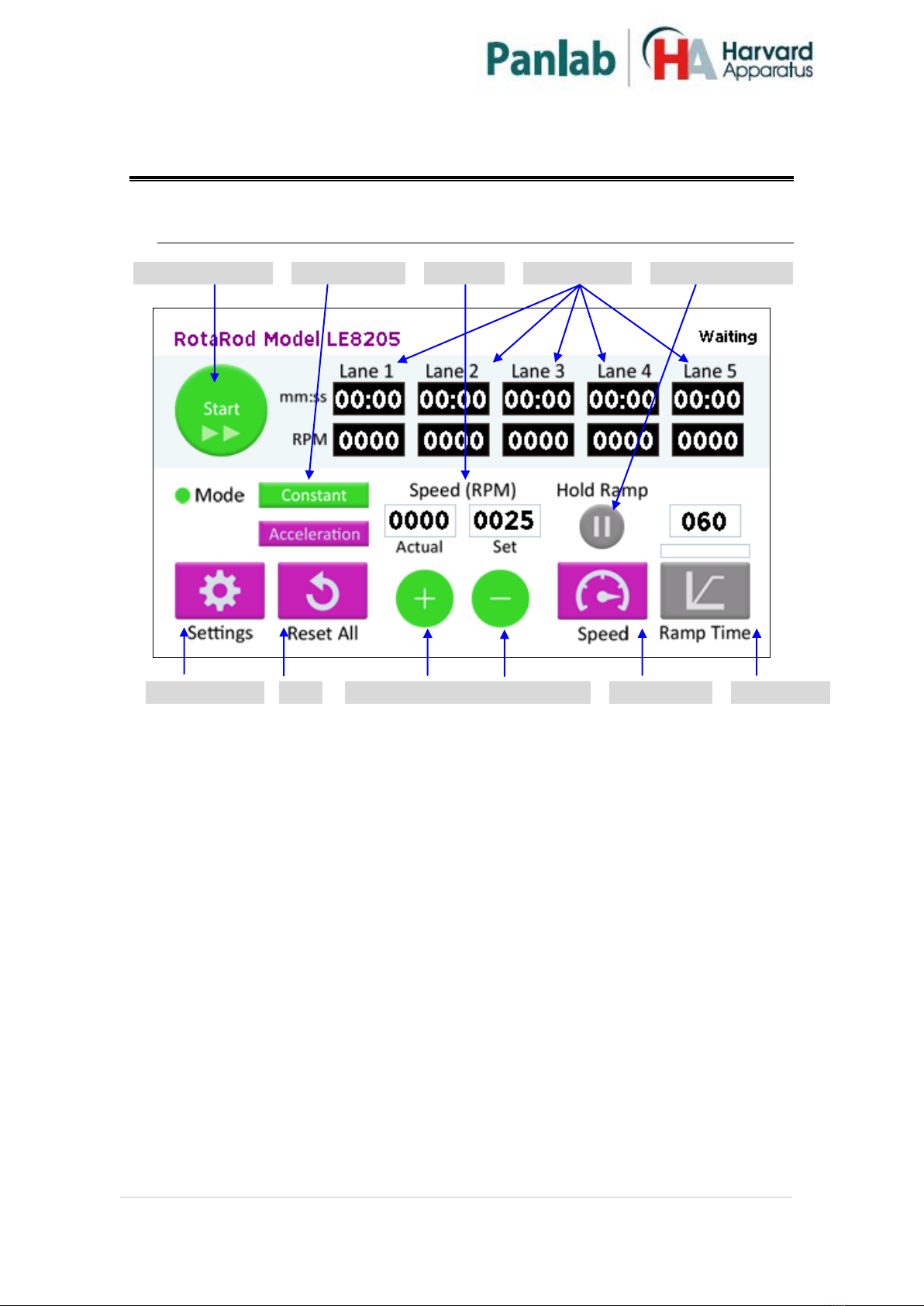
Panlab Rotarod LE8205 Instructions for use

References:
LE8205 (76-0770), LE8305 (76-0771), LE8505 (76-0772), LE8355 (76-0773)
Version:
V20/02/2015
Hardware User’s Manual
Rotarod
Panlab, s.l.u
C/Energía, 112
08940 Cornellà de Ll.(Barcelona)
Spain
www.panlab.com
International Calls: +34 934 750 697
Domestic Call: 934 190 709
Fax: +34 934 750 699

Limitation of Liability
PANLAB does not accept responsibility, under any circumstances, for any harm or
damage caused directly or indirectly by the incorrect interpretation of what is
expressed in the pages of this manual.
Some symbols may have more than one interpretation by professionals
unaccustomed to their usage.
PANLAB reserves the right to modify, in part or in total, the contents of this document
without notice.

Rotarod
2
1. SYMBOLS TABLE
Recognising the symbols used in the manual will help to understand their meaning:
DESCRIPTION
SYMBOL
Warning about operations that must not be done because they can
damage the equipment
Warning about operations that must be done, otherwise the user can be
exposed to a hazard.
Protection terminal ground connection.
Warning about a hot surface which temperature may exceed 65ºC
Warning about a metal surface that can supply electrical shock when it’s
touched.
Decontamination of equipments prior to disposal at the end of their
operative life
Waste Electrical and Electronic Equipment Directive (WEEE)
2. GOOD LABORATORY PRACTICE
Check all units periodically and after periods of storage to ensure they are still fit for
purpose. Investigate all failures which may indicate a need for service or repair.
Good laboratory practice recommends that the unit be periodically serviced to ensure
the unit is suitable for purpose. You must follow preventive maintenance instructions.
In case equipment has to be serviced you can arrange this through your distributor.
Prior to Inspection, Servicing, Repair or Return of Laboratory Equipment the unit must
be cleaned and decontaminated.
Decontamination prior to equipment disposal
In use this product may have been in contact with bio hazardous
materials and might therefore carry infectious material. Before
disposal the unit and accessories should all be thoroughly
decontaminated according to your local environmental safety laws.

Rotarod
3
3. UNPACKING AND EQUIPMENT INSTALATION
WARNING: Failure to follow the instructions in this section may
cause equipment faults or injury to the user.
A. No special equipment is required for lifting but you should consult your local
regulations for safe handling and lifting of the equipment.
B. Inspect the instrument for any signs of damage caused during transit. If any
damage is discovered, do not use the instrument and report the problem to
your supplier.
C. Ensure all transport locks are removed before use. The original packing has
been especially designed to protect the instrument during transportation. It is
therefore recommended to keep the original carton with its foam parts and
accessories box for re-use in case of future shipments. Warranty claims are
void if improper packing results in damage during transport.
D. Place the equipment on a flat surface and leave at least 10 cm of free space
between the rear panel of the device and the wall. Never place the equipment
in zones with vibration or direct sunlight.
E. Once the equipment is installed in the final place, the main power switch must
be easily accessible.
F. Only use power cords that have been supplied with the equipment. In case that
you have to replace them, the spare ones must have the same specs that the
original ones.
G. Make sure that the AC voltage in the electrical network is the same as
the voltage selected in the equipment. Never connect the equipment to a
power outlet with voltage outside these limits.
The manufacturer accepts no responsibility for improper use of the equipment or the
consequences of use other than that for which it has been designed.
WARNING
For electrical safety reasons you only can connect equipment to
power outlets provided with earth connections .
This equipment can be used in installations with category II over-
voltage according to the General Safety Rules.

Rotarod
4
WARNING
PC Control
Some of these instruments are designed to be controlled from a PC. To
preserve the integrity of the equipment it is essential that the attached PC
itself conforms to basic safety and EMC standards and is set up in
accordance with the manufacturers’ instructions. If in doubt consult the
information that came with your PC. In common with all computer
operation the following safety precautions are advised.
• To reduce the chance of eye strain, set up the PC display with the correct
viewing position, free from glare and with appropriate brightness and
contrast settings
• To reduce the chance of physical strain, set up the PC display, keyboard
and mouse with correct ergonomic positioning, according to your local
safety guidelines.
WARNING
Class A equipment is intended for use in an industrial environment.
This equipment has been tested and found to comply with the limits for a
Class A digital device, pursuant to part 15 of the FCC rules. These limits are
designed to provide reasonable protection against harmful interference
when the equipment is operated in a commercial environment. This
equipment generates uses and can radiate radio frequency energy and if
not installed and used in accordance with these instructions, may cause
harmful interference to radio communications. Operation of this
equipment in a residential area is likely to cause harmful interference in
which case the user will be required to correct the interference at his own
expense.

Rotarod
5
4. MAINTENANCE
WARNING: Failure to follow the instructions in this section may cause
equipment fault.
PRESS KEYS SOFTLY –Lightly pressing the keys is sufficient to activate them.
Equipment does not require being disinfected, but cleaned for removing urine,
feces and odor. To do so, we recommend using a wet cloth or paper with soap
(which has no strong odor). NEVER USE ABRASIVE PRODUCTS OR
DISSOLVENTS.
NEVER pour water or liquids on the equipment.
Once you have finished using the equipment turn it off with the main switch. Clean
and check the equipment so that it is in optimal condition for its next use.

Rotarod
6
TABLE OF CONTENTS
1. SYMBOLS TABLE 2
2. GOOD LABORATORY PRACTICE 2
3. UNPACKING AND EQUIPMENT INSTALATION 3
4. MAINTENANCE 5
5. INTRODUCTION 7
6. EQUIPMENT DESCRIPTION 9
6.1. FRONT PANEL 9
6.2. REAR PANEL 10
6.3. ROTAROD 11
7. EQUIPMENT CONNECTION 12
8. WORKING WITH THE EQUIPMENT 13
8.1. CHANGING SETTINGS 13
8.2. SELECTION OF THE WORKING MODE 14
8.3. PREPARING THE INSTRUMENT 18
8.4. CONDUCTING EXPERIMENTS 19
9. TRANFERING DATA TO A PC (SEDACOM) 23
10. MAINTENANCE 24
10.1. REMOVING PARTS 24
10.2. CLEANING THE UNIT 25
10.3. LEVERS FORCE ADJUSTMENT 25
11. TROUBLESHOOTING 26
12. PREVENTIVE MAINTENANCE 27
13. SPECIFICATIONS 28

Rotarod
7
5. INTRODUCTION
The LE8205 (76-0770), LE8305 (76-0771), LE8505 (76-0772) and LE8355 (76-0773)
ROTAROD units facilitate easy testing of motor activity in rodents. Drug
administration, central nervous system damage, disease effects on motor co-
ordination or fatigue can be assessed by measuring the time during which the animal
continues walking in a rotating rod.
Figure 1. LE8205 (76-0770) with rod for 5 mice
A central rod (made of Perspex, and knurled to provide adequate grip) divided in
sections, rotates at either a constant speed or a steadily accelerating rate (from 4 to
40 rpm in an interval of time ranged from 30 seconds to 10 minutes). The use of
acceleration has been reported to produce less variable data.

Rotarod
8
The ROTAROD can send the information to a PC through its USB cable connection.
This makes it possible to store and work with the data independently from the
instrument. Simply connect the PC and the ROTAROD with the interconnection cable,
and the data generated from the rod will be automatically sent to the PC. Panlab’s
Sedacom software program needs to be installed previously on the PC (must be
purchased separately).
The difference between models is:
LE8205 (76-0770) is designed to work with up to 5 mice.
LE8305 (76-0771) is designed to work with up to 4 rats.
LE8355 (76-0773) is a LE8305 modified, higher and with only two lanes for large
rats.
LE8505 (76-0772) is designed to work with up to 4 rats or 4 mice.

Rotarod
9
6. EQUIPMENT DESCRIPTION
6.1. FRONT PANEL
Figure 2. Front Panel
Start/Stop button: to start or stop the experiment.
Working mode selector: to choose the desired working mode, constant or
acceleration.
Rod speed indicators: show the current and set rod rotation speed.
Lane counters: depending on the rotarod model, this will be from two to five
columns:
1. The first row displays the time that the animals have been on the rod.
2. The second row displays the rod speed.
Hold ramp button: functional during the Acceleration working mode:
1. First press of this button starts the rod acceleration and begins the
active lane counters recording.
2. A second press maintains the current rod speed constant.
Settings screen: Displays the settings screen.
Start/ Stop button Working mode Rod speed Lane counters Hold Ramp button
Settings screen Reset Speed increase/decrease button Speed screen Ramp screen

Rotarod
10
Reset button: Clears the lane counters indicators to zero.
Speed increase/decrease button: Increments/decrements by one unit the rod
speed. Applies only to constant speed working mode.
Speed screen: Displays the Set Speed screen. Applies only to constant speed
working mode.
Ramp screen: Displays the Set Ramp screen. Applies only to acceleration
working mode.
6.2. REAR PANEL
Figure 3. Rear Panel
USB: USB B-type female connector used to connect the Rotarod to a
computer Com port. Data is sent to the Sedacom software through this
connector.
POWER: Male panel jack used to connect the Rotarod to the AC-DC adapter.
SWITCH: Main switch used to turn on and off the Rotarod.
USB POWER SWITCH

Rotarod
11
6.3. ROTAROD
Figure 4. Rotarod main parts
The Rotarod LE8305 (76-0771) and the LE8505 (76-0772) have a turning rod with 4
slots. The LE8205 (76-0770) features 5 slots and the LE8355 (76-0773), 2 slots. Rodents
(rats or mice depending of the instrument model) are placed in these slots. There is a
transparent lid fixed with magnets to the bottom face of the Rotarod to prevent that
any animal falls by the bottom part of the lever.
The 4-slot rat models (LE8305 and LE8505 with rats rod) feature an accessory to
increase the height of the walls. This accessory, the extension hood, keeps the rats
from accessing neighbouring slots.
When the animal falls from the rod, it depresses the lever trip plate at the bottom.
This lever is equipped with a switch that detects time.
A large white plastic screw is mounted on the right side of the unit. It keeps the rod in
position.
LEVERS
RAT
EXTENSION HOOD
ROTATING DRUM
DRUM LOCKING
SCREW
TRANSPARENT LID

Rotarod
12
7. EQUIPMENT CONNECTION
The equipment connection is shown in the picture 5.
Figure 5. Equipment connection
The connections and necessary cables are listed in the following table.
FROM
TO
CABLE
1
Rotarod USB-B type
PC USB Port
USB Cable
2
AC-DC adapter mains
Mains
Power cord
3
Rotarod power jack
AC-DC adapter
Jack cable

Rotarod
13
8. WORKING WITH THE EQUIPMENT
Once the equipment is turned on, the start-up screen appears after a few seconds:
Figure 6. Start-up screen
8.1. CHANGING SETTINGS
The following options can be modified thorough the Settings screen:
Figure 7. Settings options
Motor direction: Establishes the rod rolling direction: forward and reversed.
Display backlight: Establishes the percentage of backlight of the display.

Rotarod
14
Figure 8. Backlight settings screen
Upgrade software: Used to update the firmware to the latest version.
System Information: Displays the Rotarod model type, the firmware version
number and serial number of the device.
8.2. SELECTION OF THE WORKING MODE
A) CONSTANT MODE
Figure 9. Screen in Constant mode
The motor works to provide a speed from 4 to 40 rpm, depending on the needs
of the user, who can select the speed either before starting the experiment or
when it is already underway. The speed is the same for each lane, as there is a
single motor driving the single rod on which all the subjects are moving.

Rotarod
15
The starting point of the TIMERS is determined when the relevant LEVER is
lifted; each TIMER works independently from the others. The end point of each
TIMER is determined when the relevant LEVER is lowered.
B) ACCELERATION MODE
The motor increases speed automatically and lineally from 4 up to 40 rpm,
thus producing a constant acceleration of the rod. The speed is the same for
each lane, as there is a single motor driving the single rod on which all the
subjects are moving.
It is possible to determine the ACCELERATION TIME that the rod will take to
achieve the maximum speed. The TIME SLOPE may range from 30 seconds up
to 10 minutes.
Once the maximum has been achieved, the rod continues at this speed.
When working in this mode, two states and one optional state exist:
WAITING:
Figure 10. Screen in acceleration mode waiting
This is the first state after pressing the Start button in this mode.
This is the preparation state of the instrument in order to place the subjects in
their respective slot on the rod. The speed of the rod for this phase of
preparation is the minimum, 4 rpm.
Levers must be lifted to be ready to begin the experiment.

Rotarod
16
ACCELERATION:
Figure 11. Screen in acceleration mode running
This is the second state after pressing the Hold Ramp button in this mode.
The motor ramps from 4 to 40 rpm, following the predetermined SLOPE TIME
once the Hold Ramp button has been pressed.
After the ramp is initiated, the ACCELERATION TIME cannot be changed.
The TIMER counters corresponding to the raised LEVERS, begin recording the
time after the Hold Ramp button is pressed.
Once the relevant LEVER is depressed, the TIMER will show the total rotating
time as the end point for that subject on that particular trial.
When the last subject falls from the rod, the instrument automatically enters
the STOP state.

Rotarod
17
ACCELERATION-CONSTANT:
Figure 12. Screen in acceleration-constant mode running
This is the third optional state reached after pressing the Hold Ramp button
again in this mode.
The motor stops the acceleration and keeps running constantly in the current
rod speed.
The TIMERS counters corresponding to the raised LEVERS, continue
incrementing.
The end point of each TIMER is marked when the relevant LEVER is lowered.
When the last subject falls from the rod, the instrument automatically enters
into the STOP state.

Rotarod
18
8.3. PREPARING THE INSTRUMENT
Figure 13. Placing the animal in the roll
Holding the animal by its tail, swing them up from a position lower than the
rod, so that they find themselves walking inside.
It is advisable to set the cylinder in motion before placing the animals on the
rod. Otherwise, by the time the last animal has been seated in position, the
first animal may be facing the wrong direction.
It is also advisable to let the animal familiarize with the rod by having them
walk at minimum speed for a few moments.

Rotarod
19
8.4. CONDUCTING EXPERIMENTS
1) Turn on the instrument using the POWER switch.
2) Lower the LEVERS, this will prevent the timer counters from beginning.
3) Select the desired working mode.
a) CONSTANT
1) Establish the desired initial rod speed using the “+”, “-”or “Speed” buttons. The
rod will not begin rotating until the “Start” button is pressed.
Figure 14. Set rod speed screen
2) Press the “Start” button and this will initiate the rod rotation at the set speed
in step 1.
3) If any LEVER remains in the raised position, the message “Place all levers
down” will be shown on the display until all the LEVERS are in depressed
position.
4) Place the animals in their respective lanes on the rod, as shown in Section 8.3.
5) Manually lift the LEVERS to activate the relevant counters for the lanes that
will be used in that trial.
6) Use the “+”, “-”or “Speed” buttons to modify the desired rod speed.
Accept, cancel changes buttons
Edit the speed in this box by pressing the numbers on the keypad
Keypad
This manual suits for next models
7
Table of contents
Popular Laboratory Equipment manuals by other brands

GR Scientific
GR Scientific Aquamax KF user manual

VERDER
VERDER Carbolite Gero HTMA 4/28 Installation, operation and maintenance instructions

Dionex
Dionex ICS-2100 installation instructions

Labnet
Labnet BioPette PLUS BPP2 Instuction manual

Grizzly
Grizzly 1160W UVC quick start guide

Bullard
Bullard TXS instruction manual