Panther Foxy Pro User manual

INSTRUCTION MANUAL
FOXY PRO
PANTHER GMBH
Raieisenallee 3, 82041 Oberhaching-Munich
Tel.: +49 89 - 613 900 01 | Fax: +49 89 613 1000
www.panther.tv | contact@panther.tv

Instruction Manual - TABLE OF CONTENT
FOXY PRO
PASSION OF MOVEMENT www.panther.tv
1. Introduction 1
2. To the grip 1
3. Safety advice 2
4. Information on load (payload): 4
5. Check-List for assemby 5
6. Quick Guide FOXY PRO 10
7. Setup instructions 11
7.1 Preparation 11
7.2 Assembly - Remote Version 8 12
7.3 Assembly - Platform Versions 1 - 4 30
8. Start of Operation 31
9. Transport 32
10. Service and Maintenance 33
11. Warranty 34
12. Inspection Book 35
12.1 EU - Declaration of Conformity 35
12.2 Recurrent inspection136
12.3 Maintenance Booklet 37

Instruction Manual
FOXY PRO
PASSION OF MOVEMENT www.panther.tv1
1. Introduction
Congratulations to your decision to buy or rent a PANTHER - FOXY PRO Cranesystem. We
are very pleased that you have chosen our product, which combines state-of-theart
technology as well as the experience of many years in manufacturing camera
cranes and dollies.
High-quality material and sound know-how, as well as a clever concept enable your PANTHER
- FOXY PRO Cranesystem. to do a professional job, which you will really enjoy when doing your
responsible work at the set.
Your new PANTHER - FOXY PRO Cranesystem.is a high-quality tool, which enables the
creative camera man to do an excellent job – fast and easy – with fantastic shots and camera
drives.
The PANTHER FOXY Crane is a product that has been created and built by experts for experts – to
satisfy the high demands of every grip and camera man.
In order to guarantee the highest security and reliability in our product at the set,
please study our operating manual very carefully!.
All the best
PANTHER GmbH
2. To the grip
Sloppy assembly, disassembly and operating have created and will also create in future da-
mages and physical injury, as well as death of involved or even uninvolved persons.
The following operating instructions should explain to the grip how to work with the camera
crane and should also make aware and give advice to take care of possible dangers.
Accidents can only be avoided if the dangers are well known and the common sense is activa-
ted.

Instruction Manual
FOXY PRO
PASSION OF MOVEMENT www.panther.tv2
3. Safety advice
The FOXY PRO crane system may only be operated by competent and trained
personnel. It may only be used to carry cameras and their operators for use in
motion picture production.
PANTHER regularly holds training workshops for which participants receive a certicate on com-
pletion. Please call +49 (89) 6 3 900 0 for further information.
Only use the crane after having read and understood the operating manual. Safety guidelines
as well as weight and dimension specications must be adhered to. Servicing and maintenance
guidelines must be observed.
The crane may not be used directly before, during or after thunderstorms. There could be a
risk of lightning striking. When not directly in use, the crane should be dismantled or secured
against wind.
Should a storm arise, the crane should be not be operated and must be stowed away or parked
safely according to DIN 15019 part 1/6.1.3. The crane may not be operated near power transmis-
sion lines.
If the crane is used in an elevated area (e. g. bridge, multistory building, you should minimize
the risk of falling from the increased height by additionally securing the crane and personnel
with adequate safety ropes to appropriate objects (e. g. concrete pillars).
CAUTION !
The crane may not be used when wind speeds are 32 km/h (remote versi-
on)/22 km/h (platform version) or higher. Stow or park the crane safely in a
timely manner, according to DIN 15019 part 1/6.1.3.
Always keep the crane’s (plus all outriggers’) lifting, panning and driving range free of obstruc-
tion. Always observe 0.5 m clearance distance to people and objects in the proximity. Beware of
pinching and anticipate pinch points during assembly and operation of the crane.
The crane operator is responsible for keeping the remote head mount free of loose objects; they
could fall and cause injury. The Remote Head and the camera must be secured to the Remote
Mount with a safety cable.
ATTENTION !
Only use original PANTHER components and accessories. Combined seat-
extensions (vertical/horizontal) with order numbers 110, 111, 112, 105663,
105662 or 105661 may NOT be used. Only use vertical seat-extensions, or
combined seat-extensions marked with„HD“ (heavy duty).

Instruction Manual
FOXY PRO
PASSION OF MOVEMENT www.panther.tv3
ATTENTION !
The FOXY PRO crane system may not be used on inclined surfaces. The crane
must be secured against inadvertent movement. The ground should be hard
and rigid. The ground’s minimum load capacity must be at least 3000 kg/
m²
.
Do not overload the remote mount’s maximum loading capacity. Only use the respectively
permissible amount of counterweights that t into the counterweight basket. They must be
securable, and also compact (e. g. not sandbags or waterbags). Non-spec or improvised coun-
terweight material may not be used (e. g. sandbags).
The weight of the complete crane build, with accessories and people, must be taken into consi-
deration when considering the ground’s load capacity, tracks and/or foundation.
Foundation material such as wedges and blocks must be placed such that they cannot slide or
be kicked aside inadvertently. Clamps or similar safety guards should be attached to the ends of
tracks, in order to prevent the crane from falling or rolling o the track.
Repairs may only be made by the manufacturer or trained and competent persons. PANTHER
oers service seminars, which are held from time to time. For exact dated, please call +49 (89)
613 900 30 (PANTHER Service).
When the crane is stowed or parked, the crane must be secured from being used by unauthori-
zed persons and, if necessary, appropriate provisions made against storm winds.
In any case, before using the crane, its stability against overturning must again be checked and
tested with the maximum overturning load.
When the crane is being used in a studio or on tracks, please take care that no hard or loose
objects can get underneath the wheels. Even small spots of unevenness may endanger secure
standing and driving.
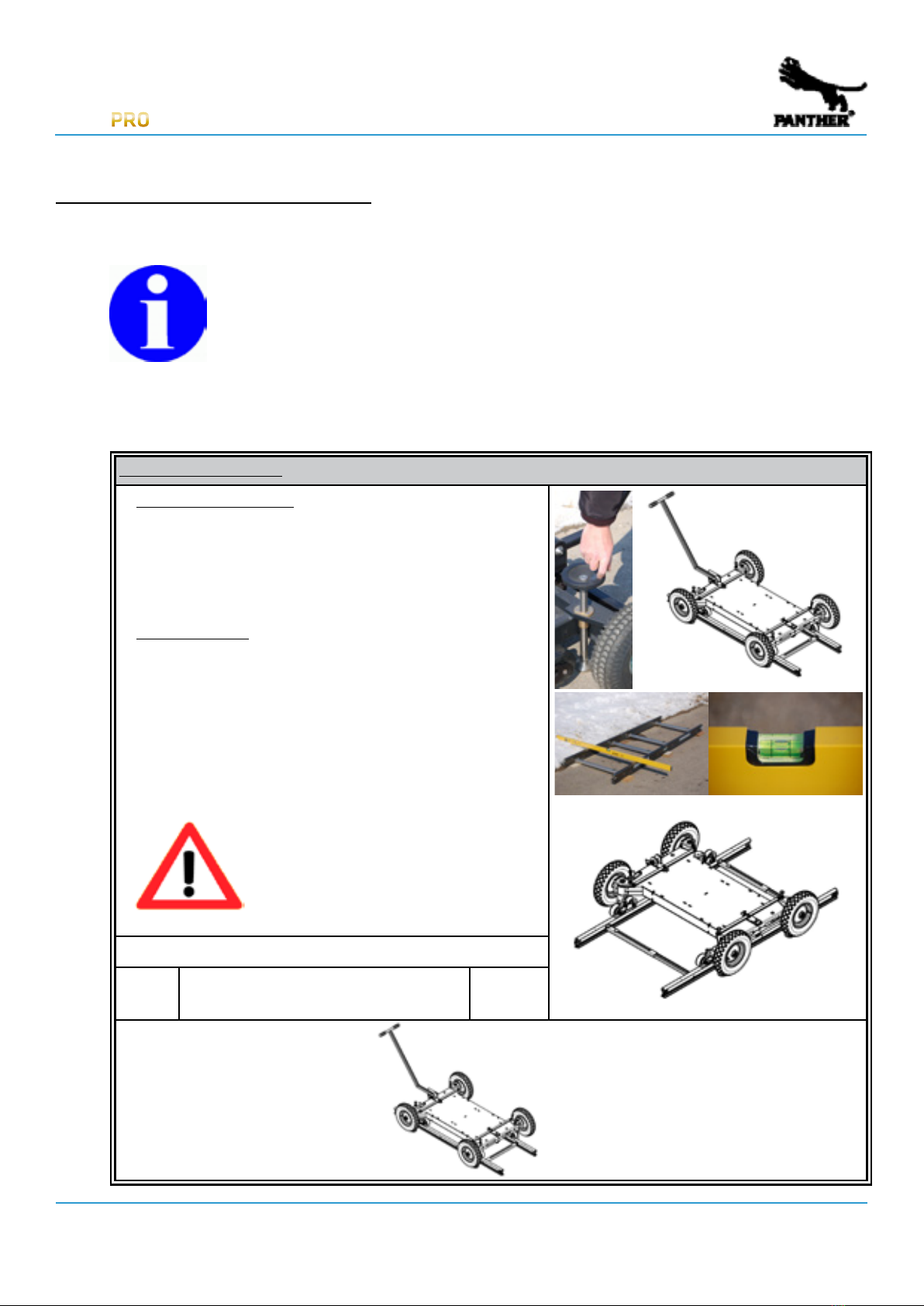
When assembled, the FOXY PRO crane system may only be moved on a PANTHER track system or,
on smooth ground, with studio wheels made out of solid rubber (order number 128825). The as-
sembled FOXY PRO crane system may not be moved on pneumatic wheels. If pneumatic wheels
are attached to the crane, all 4 spindles must connect with the ground and carry the complete
load.
Do not use the crane with a manned platform during natural or articial extreme weather condi-
tions such as strong rain, thunderstorms, extreme heat or cold if the people are not adequately
protected and secure.
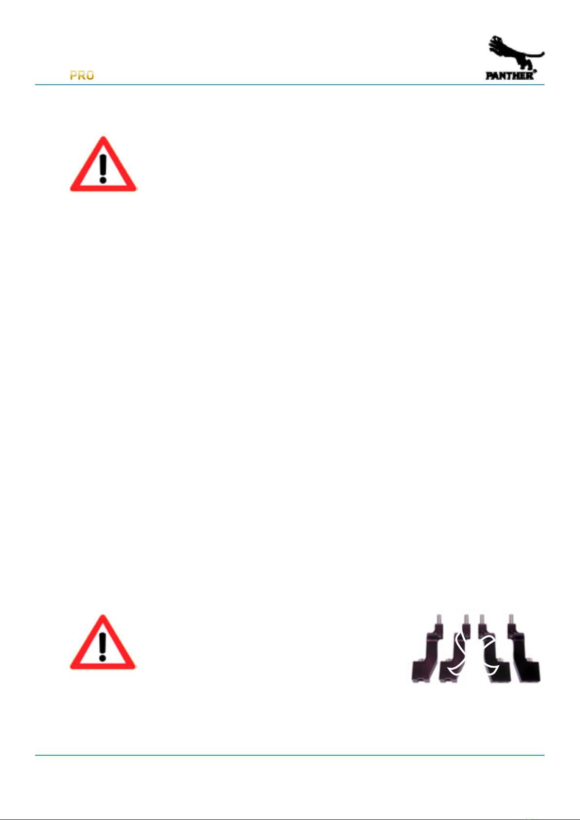
ATTENTION !
Do NOT use PANTHER wide base adapter (code
no. 133128) ! The payload of the adapter is insu-
cient for the FOXY PRO Crane System. O

Instruction Manual
FOXY PRO
PASSION OF MOVEMENT www.panther.tv4
4. Information on load (payload):
ATTENTION !
The crane operator is obligated to inform all persons on the platform that they
must fasten their seatbelts. The persons may only get down from the platform
after the counterweights are taken out of the counterweight basket.
The remote head mount’s load capacity involves all elements that are attached to it (e. g. Mit-
chell Adapter, Remote Head, camera, lens etc.).
The PANTHER FOXY PRO crane system may only be assembled according to the options described
in this operating manual. Other assembly options are not allowed (see quick guide - chapter 6).
When panning and turning the crane outrigger, and when driving curves, centrifugal forces are
generated which can add up and may possible aect stability
For safety reasons, the crane should always stand or move on a foundation that has been che-
cked as absolutely stable and level. When driving the crane, ensure that no objects can get
underneath the wheels and inuence stability. The crane may not be used with curved track.
Check the crane daily regarding function, damage or missing parts. Damaged and/or missing
components must be promptly be replaced with new PANTHER original spare parts.
Mark the crane’s working range (driving and tilting range) with ags, signs or similar material.
Keep all persons away from the working range, in order avoid any possible contact with the out-
rigger and/or dolly. .
IMPORTANT !
The camera may only be mounted and dismantled (with or without remote
system) when the crane operator has given his consent. Change of load on
one side of an already balanced crane will cause an abrupt imbalance which
in turn can cause the outrigger to abruptly rise and may result in damage to
the crane and, possibly, major injuries.
Check the crane’s operating area with a regard to possible risks. Do a test run before each ope-
ration. Assume that people in the audience may suddenly get up or change their position.
Do not let the outrigger impact mechanically at the end of the tilting range. Immediately stop
using the crane should any part of the crane be damaged or not assembled correctly.

Instruction Manual
FOXY PRO
PASSION OF MOVEMENT www.panther.tv5
5. Check-List for assemby
Please check which conguration is best for your shooting.
The following criteria have to be considered:
• height • limits in weight
• working distance • payload required
• spatial limits • access to shooting place
Take your time to securely assemble, to check and to test the system before use.
1. Transport Do not expose / subject the outriggers and rods to heavy blows or
impacts; do not bend ropes.
2. Auxiliaries Water level
Support device (e.g. small ladder, tripod, etc.)
3. Ground No slope: check with water level
Create level surface in case of a slope
If the ground’s loading capacity is lower than 3000 kg/ m² the load
has to be distributed with an adequate foundation
4. Basis No slope: check with water level
foundation with min. 3000 kg/ m² load capacity
5. Assembly Check whether all necessary parts are present
Assemble according to instructions
Observe safety instructions
confirmation for stability against overturningavailable
CAUTION !
If the outrigger is loaded in only one direction, outriggers have to be
supported under the load center of gravity. It is obligatory to observe the
safety instructions of the operating manual.

Instruction Manual
FOXY PRO
PASSION OF MOVEMENT www.panther.tv6
6. Quick Guide FOXY PRO
265 kg / 585 lbs
5,8m / 19ft.
3
250 kg / 550 lbs
2,45m/ 8ft.
7,3m / 24ft.
4
170 kg / 375 lbs
2,45m/ 8ft.
max. Height/Höhe:
6,1m(20ft.)
max. Height/Höhe:
7,3m(24ft.)
Front side / Vordere Seite:
Optional High rig
(remote only)
+ 80 cm / + 3 ft.
+ 1 m / + 3.5 ft.
2,45m / 8ft.
Rear side / Hintere Seite:
2,15m / 7ft.
1,85m / 6ft.
Quick Information
Schnellinformation
Please look into operating manual
for further information!
Bitte beachten Sie die Betriebsanleitung
für weitere Informationen!
Platform Versions:
Foxy PRO
Foxy PRO
Crane System:
265 kg / 585 lbs
2,8m / 9ft.
1
2,45m/ 8ft.
16
150 kg / 330 lbs
4,3m / 14ft.
2
2,45m/ 8ft.
16
max. Height/Höhe:
3,7m(12ft.)
max. Height/Höhe:
4,9m(16ft.)
Trapezoid / Trapez:
1,8 m / 6 ft.
2,2 m / 7 ft.
2,9 m / 9.5 ft.
Standard Trapezoid
(all versions)
1,8 m / 6 ft.
2,5 m / 8 ft.
optional Trapezoid compact
(up to version 6)
2,2 m / 7 ft.
4,3m / 14ft.
2.1
2,45m/ 8ft.
30
1 Panther counterweight / Gegengewicht = 17kg (37.5lbs)
39
4
39
4
39
4
Necessary number of Panther
counterweights in additional bucket
(e.g. 4 pcs.)
Necessary number of Panther
counterweights in bucket (e.g. 39
pcs.) for max. payload.
Special
length,
versions
and
accessories
on
request!
Note:
The measurements
and weights may differ
up to 2% due to
production tolerances.
Hinweis:
Die Masse u.
Gewichte kˆnnen
aufgrund
Fertigungstoleranzen
um 2% abweichen.
max. Height/Höhe:
4,9m(16ft.)
Foxy PRO
39
4
39
4
39
4
39
4
39
4
5,7m / 18.5ft.
3
80 kg/ 176lbs.
2,45m/ 8ft.
16
4,2m / 13.5ft.
2
80 kg/ 176lbs.
2,45m/ 8ft.
9
2,7m / 8.5ft.
1
80 kg/ 176lbs.
2,45m/ 8ft.
4
10,2m / 33.5ft.
6
80 kg/ 176lbs.
2,45m/ 8ft.
8,7m / 28,5ft.
5
80 kg/ 176lbs.
2,45m/ 8ft.
30
7,2m / 23.5ft.
4
80 kg/ 176lbs.
2,45m/ 8ft.
24
5,7m / 18.5ft.
3.1
80 kg/ 176lbs.
2,45m/ 8ft.
18
13,2m / 43.5ft., with High Rig 14m/46ft.
8
25 kg/ 55 lbs.
2,45m/ 8ft.
12,6m / 41.5ft., with High Rig 13,4m/44ft.
8.1
30 kg/ 65 lbs.
2,45m/ 8ft.
11,7m / 38.5ft.
7
50 kg/ 110 lbs.
2,45m/ 8ft.
11,1m / 36.5ft.
7.1
55 kg/ 120 lbs.
2,45m/ 8ft.
Remote Versions:
max.
Height/
Höhe:
12,3m
(40.5ft.)
max.
Height/
Höhe:
11,8m(39ft.)
max.
Height/Höhe:
11,1m(36.5ft.)
max. Height/Höhe:
10,5m(34.6ft.)
max. Height/Höhe:
9,8m(32.3ft.)
max. Height/Höhe:
8,6m(28.3ft.)
max. Height/Höhe:
7,4m(24.3ft.)
max. Height/Höhe:
6,1m(20ft.)
max. Height/Höhe:
6,1m(20ft.)
max. Height/Höhe:
4,9m(16ft.)
max. Height/Höhe:
3,7m(12ft.)
4,2m / 13.5ft.
2.1
80 kg/ 176lbs.
2,45m/ 8ft.
max. Height/Höhe:
4,9m(16ft.)

Instruction Manual
FOXY PRO
PASSION OF MOVEMENT www.panther.tv7
7. Setup instructions
7.1 Preparation
a) Ground
The ground must be rm and level. If there is an incline, specialized substructures or tracks
with an adequate foundation must be used.
ATTENTION !
The ground’s minimum loading capacity must be 3000 kg/m².
b) Foundation
The foundation must be built carefully and without slope. It is especially important to take
care that supporting material (e. g. wedges) cannot be dislodged or moved inadvertently.
ATTENTION !
The foundation’s minimum loading capacity must be 3000 kg/m².
c) Track operation
Please heed the information in the operating manual respective to the track system. Use
only original PANTHER track systems.
During the track build, the dolly brakes must be activated.
ATTENTION !
During track operation, the tracks must be level. No slopes allowed!

Instruction Manual
FOXY PRO
PASSION OF MOVEMENT www.panther.tv8
Step 1 - Base buildup
Base on rm ground
Activate brakes on base to prevent it rolling away
during buildup. If the ground is not 100 % level,
use the spindles to level the base.
Basis on tracks
The foundation must be made carefully and without
slope. Heed the information contained in the
utilized track system’s operating instructions. The
dolly must be braked during assembly.
ATTENTION !
Ground loading capacity:
3000 kg/m² minimum
Necessary components:
1 x Big Base (incl. 4x pneumatic wheels,
4x track wheels, 4x spindles)
200183
7.2 Assembly - Remote Version 8
In the following there is a description of how the FOXY PRO crane system Version 8 is assembled.
INFO !
Versions 1 - 7 are assembled in the same manner, but respectively less outrig-
gers and anchor poles are mounted at the front side (on the remote mount/
platform).

Instruction Manual
FOXY PRO
PASSION OF MOVEMENT www.panther.tv9
Step 2 - Attach Pyramid
• Set the pyramid on the base and screw tight.
Necessary components:
1 x Foxy pyramid for 9 outrigger 156530
Step 3 - Attach Center Pivot Section
• Set the center pivot section on the pyramid and
screw tight.
ATTENTION !
Check the bubble level again
to ensure that the center pivot
section is correctly levelled.
Necessary components:
1 x
Central pivot section FOXY PRO
156773

Instruction Manual
FOXY PRO
PASSION OF MOVEMENT www.panther.tv10
Step 4 - Mount Outrigger 150cm & Balance rod
• Hook Outrigger 150cm into Central Pivot Section.
• Screw in connecting screw by hand.
• Clamp the connection tight by using the locking
lever.
• Attach the Balance Rod for Outrigger 150cm to
the square end on the Central Pivot Section and
lock with Quickpin.
• Attach Balance Rod to the holder on Outrigger
150cm and lock with Quickpin.
Necessary components
1 x Outrigger with balance rod, 150 cm
/ 4‘11“
302256

Instruction Manual
FOXY PRO
PASSION OF MOVEMENT www.panther.tv11
Step 5 - Mount Outrigger 150cm, Outrigger tail 15cm, anchor pole axis & Balance Rod
• Hook Outrigger 150cm with Outrigger tail 15cm
with balance rod and with anchor pole axis in
Central Pivot Section.
• Screw in connecting screw by hand.
• Clamp the connection tight by using the locking
lever.
• Attach the Balance Rod for Outrigger 150cm and
for Outrigger tail 15cm to the square end on the
Central Pivot Section and lock with Quickpin.
Necessary components:
1x Outrigger with balance rod, 150 cm
/ 4‘11“
302256
1x Outrigger tail 15cm with balance
rod
136770
1x Anchor pole axis 302090

Instruction Manual
FOXY PRO
PASSION OF MOVEMENT www.panther.tv12
Step 6 - Mount Outrigger 150cm & Balance Rod
• Hook Outrigger 150cm.
• Screw in connecting screw by hand.
• Clamp the connection tight by using the locking
lever.
• Attach the Balance Rod for Outrigger 150cm to
the square end and lock with Quickpin.
• Attach Balance Rod to the holder on Outrigger
150cm and lock with Quickpin.
Necessary components:
1 x Outrigger with balance rod, 150 cm
/ 4‘11“
302256

Instruction Manual
FOXY PRO
PASSION OF MOVEMENT www.panther.tv13
Step 7 - Attach Counterweight Basket
• Put up crane outrigger.
• Activate vertical brake.
• Hook Counterweight Basket to backside
Outrigger .
• Screw together using red knurled screws on
both sides.
• Attach Balance Rods to Counterweight Basket
and lock with Quickpin.
• Level out Counterweight Basket with turnbuckle.
Necessary components:
1 x Counter weight bucket for 39 w. 169310

Instruction Manual
FOXY PRO
PASSION OF MOVEMENT www.panther.tv14
Step 8 - Mount Outrigger 150cm, anchor pole axis & Balance Rod
• Hook Outrigger 150cm with with balance rod and
with anchor pole axis in.
• Screw in connecting screw by hand.
• Clamp the connection tight by using the locking
lever.
• Attach the Balance Rod for Outrigger 150cm to
the square end and lock with Quickpin.
• Attach Balance Rod to the holder on Outrigger
150cm and lock with Quickpin.
Necessary components:
1x Outrigger with balance rod, 150 cm
/ 4‘11“
302256
1x Anchor pole axis 302090

Instruction Manual
FOXY PRO
PASSION OF MOVEMENT www.panther.tv15
Step 9 - Attach Trapezoid
• Lower crane outrigger
• Lock the vertical brake.
ATTENTION !
When attaching the trapezoid, do
not step on the pyramid. Always
use a ladder!
• Mount rst side of trapezoid to Central Pivot
Section. The side of the trapezoid with a recei-
ving pin should face towards the Counterweight
Basket.
ATTENTION !
The trapezoid should be mounted
by two people, for safety reasons.
• Attach the horizontal connecting rod and lock
with Quickpin.
• Attach the opposite side of the trapezoid to the
Center Pivot Section and the horizontal connec-
ting rod.
Necessary components:
1 x Trapezoid 156819

Instruction Manual
FOXY PRO
PASSION OF MOVEMENT www.panther.tv16
Step 10 - Attach Rear Anchor Pole
• Hook rear anchor pole in weights outrigger and
secure with retaining ring.
• Hook rear anchor pole in trapezoid and secure
with retaining ring.
• Tension rear brace evenly on both sides using
turnbuckle, hand-screwed.
ATTENTION !
Turnbuckles must be tensioned!
The Balance Rod rings should lie
against the outer edge!
Necessary components:
2 x Anchor pole back, 165 cm / 5‘5“ 156909
Step 11 - Attach rst, front Extension Rod
• Hook the Base Anchor Pole in the outer eye of the
trapezoid and secure with retaining ring
• Insert one Anchor Pole Extension respectively
into Base Bracing Rod and lock with Quickpin.
• Attach variable Front Anchor Pole and hook in eye of
anchor pole axis; secure with retaining ring.
• Tension the Bracing Rods evenly on both sides
with turnbuckles, hand-screwed.
O
P

Instruction Manual
FOXY PRO
PASSION OF MOVEMENT www.panther.tv17
ATTENTION !
Turnbuckles must be tensi-
oned ! The Balance Rod rings
should lie against the outer
edge!
ATTENTION !
Watch out for exing of
crane! The crane outrigger
must be straight.
Necessary components:
2 x Base Anchor pole 157129
2 x Anchor pole extension 157381
2 x Anchor pole variable, front 157124
O
O
P
O
P

Instruction Manual
FOXY PRO
PASSION OF MOVEMENT www.panther.tv18
Step 12 - Balance the Crane
• Put approx. 4 counterweights into Counter
weight Basket.
ATTENTION !
When the Counterweight Basket is
being loaded, an assistant should
secure the crane outrigger against
rising abruptly.
Necessary components:
4 x Counterweight Crane 109023
Step 13 - Attach Outrigger 150cm & Balance Rod
• Hook Outrigger 150cm.
• Screw in connecting screw by hand.
• Clamp the connection tight by using the locking
lever.
• Attach the Balance Rod for Outrigger 150cm to
the square end and lock with Quickpin.
• Attach Balance Rod to the holder on Outrigger
150cm and lock with Quickpin.
Necessary components:
1x Outrigger with balance rod, 150 cm
/ 4‘11“
302256
Table of contents
Other Panther Construction Equipment manuals
Popular Construction Equipment manuals by other brands

Dynapac
Dynapac CA144 instruction manual

ECOVOLVE
ECOVOLVE ED1000 Operator's handbook

KPI-JCI
KPI-JCI Fast Pack K400FP Crushing Plant Operation Manual and Parts Book

Signode
Signode 4A1-114 Operation, parts and safety manual

Manitou
Manitou PRIVILEGE E3 Use manual

Graco
Graco LineLazer 3000 Instructions-parts list