Page ‑ 7
Manual | English
weight*
max. length
max. height
* without tripod
Eigengewicht*
Max. Länge
Max. Höhe
* ohne Stativ
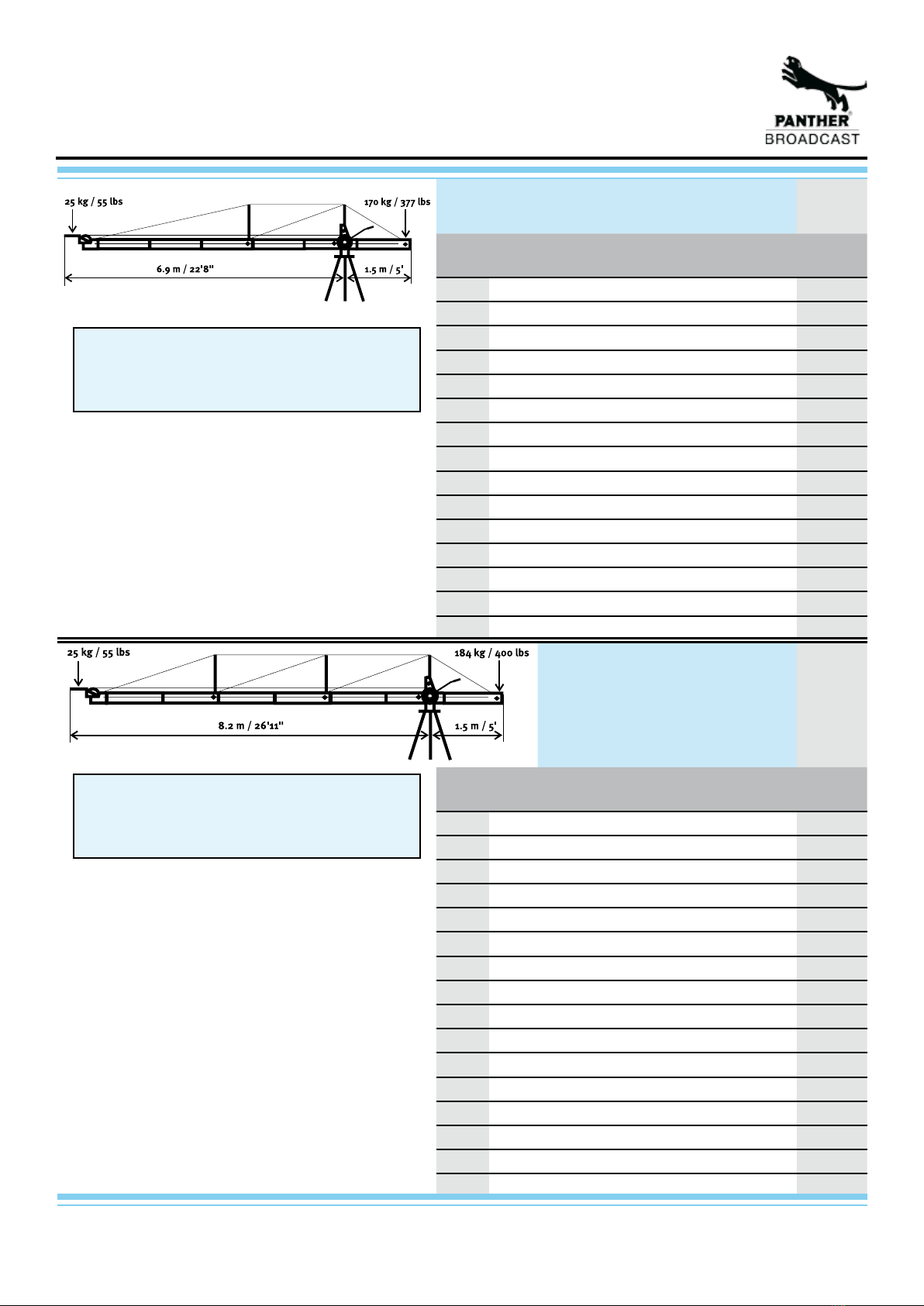
25 kg / 55 lb
8.4 m / 27‘7“
7 m / 23‘
PIXY crane, version 5
PIXY Kran, Version 5
Qty.
Anzahl
consisting of
bestehend aus
code no.
Art.-Nr.
1 Pixy Tripod Pixy Stativ 138892
1 Central pivot section Mittelteil Pixy Kran 143788
1 lifting rod Pixy Hebelstange Pixy 137363
1 carrier tube Trägerrohr 143777
1 rear tube Endrohr 137097
1 weight bar Gewichtsstange 142297
3 extension tube Verlängerung 137096
1 ext. tube for bracing Verl. für Abstützung 137342
1 Mount Pixy Galgen Pixy 137098
1 base bracing Basisabspannung 137106
1
Bracing ext. for V3/5/7
Abspannungsverl.für V3/5/7
157242
1 Bracing cable V4 Abspannung V4 138383
1
Balance rod 1.6 m / 5‘3“
Parallelogramm 1,6 m 142404
3
Balance rod 1.3 m / 4‘3“
Parallelogramm 1,3 m 142405
1
Balance rod support
Parallelogrammstütze 142406
PIXY crane, version 6
PIXY Kran, Version 6
weight*
max. length
max. height
* without tripod
Eigengewicht*
Max. Länge
Max. Höhe
* ohne Stativ
29 kg / 64 lb
9.7 m / 31‘10“
8 m / 26‘3“
Qty.
Anzahl
consisting of
bestehend aus
code no.
Art.-Nr.
1 Pixy Tripod Pixy Stativ 138892
1 Central pivot section Mittelteil Pixy Kran 143788
1 lifting rod Pixy Hebelstange Pixy 137363
1 carrier tube Trägerrohr 143777
1 rear tube Endrohr 137097
1 weight bar Gewichtsstange 142297
3 extension tube Verlängerung 137096
2 ext. tube for bracing Verl. für Abstützung 137342
1 Mount Pixy Galgen Pixy 137098
1 base bracing Basisabspannung 137106
1
Bracing ext. for V3/5/7
Abspannungsverl.für V3/5/7
157242
1 Bracing cable V4 Abspannung V4 138383
1 Bracing cable V6 Abspannung V6 138397
1
Balance rod 1.6 m / 5‘3“
Parallelogramm 1,6 m 142404
4
Balance rod 1.3 m / 4‘3“
Parallelogramm 1,3 m 142405
2
Balance rod support
Parallelogrammstütze 142406