Pantong Metodo2 User manual

Page 1
Operation Manual
Tone Generator & Amplifier Probe
Amplifier Probe
Features
•Designed to identify and trace wires without necessary damaging the
insulation.
•Works with any Tone Generator.
•Volume control for sensitivity adjusting to suit working environment.
•Recessed ON/OFF button switch to prevent battery drain while standby.
•Power supply by 9V battery with an average operating life of 100 hours.
•Audio earphone jack for operating in noisy environment such as server
room,etc.
•LED for illustration of signal strength of tone receiving.
Figure 1 Amplifier Probe
Figure 2 Tone Generator
Audio jack
Volume
control
ON/OFF button
LED
Black
Red
Modular plug
LED
3-position
toggle
switch
Tone Generator & Amplifier Probemust be installed 9V. battery before operation
IMPORTANT
Do not connect Tone Generator unit to live AC power line (220/110 VAC) or
DC power line which exceed 120 VDC.

Page 2
Tone Generator
Features
•Red and black alligator clip test leads for connecting in sending tone.
•A 3-position toggle switch for selecting mode of operation, a 3-colored LED
for indicating line polarity, continuity, ring-in voltage, etc .
•A tone selector switch, located on PCB inside the case for selecting either
a single solid tone, or dual alternating tone.
Operation
A) WIRE TRACING
1. SENDING TONE
Switch 3-position toggle switch on Tone Generator to “TONE”
(selection for dual alternating tone or a single solid tone can be
done by slide switch on PCB inside). Connection the tone generator
to line pair has 2 methods.
OFTEN USE METHOD (GROUNDED) :
Connect red clip to a wire and connect black clip to ground or large
metal part for example rack/ cabinet. (See figure 3) This method
provide strongest tone and often use.
If connection point is RJ11/RJ45 jack, please use a self-made
modular plug to copper adaptor (See figure 3) for connection with
red clip. This adaptor made by stripping all wires and short together
Figure 3 OFTEN USE METHOD (GROUNDED)
Figure 4 OPTIONAL USE METHOD (PAIRED)
Red clip
Black clip
Momentarily
short to
stop tone
Red
Black
Red clip
(Black clip to ground)
Adaptor:
RJ11/45 mod
plug to
copper lead

Page 3
the coppers (4/8 wires for RJ11/RJ45 ) one end, and terminating
modular plug the other end.
OPTIONAL USE METHOD (PAIRED) :
Connect one clip to a wire and connect the other clip to the other
wire of pair(See figure 4). This method can further verify if tracing
pair is the target by momentarily shorting the pair at trace end and
found that the tone is stop.
2. PROBE TRACING
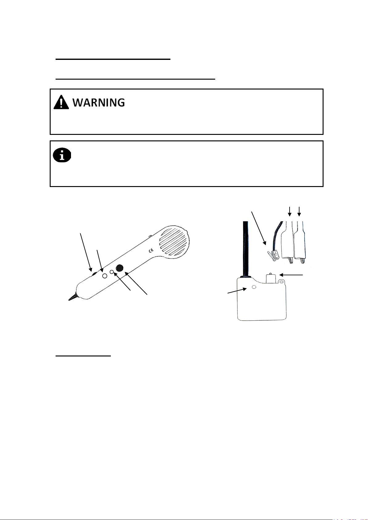
•Press the round on/off spring-loaded button of the amplifier probe.
The volume control switch can be adjusted to suit the environment.
Do not adjust volume with sound too high for better identifying
target pair from crosstalk pairs.
•Touch the tip of the amplifier probe to the insulation of each
suspected pair.
•Speaker will receive tone which will be loudest on the target pair.
•Alternative using LED as visual tracing by observing its brightness.
Brightest LED indicate receive of tone from the target pair.
If using in high background noise or crosstalk ( other wires in group
also have tones). It may needs to set volume to the level which
cancel brightness of background noise or crosstalk from LED before
tracing. Setting done by pressing button on probe, touch the tip to
those wires which havebackground noise or crosstalk, and adjust
volume down slowly from position high to low until LED brightness
cut off or very fade. Then start tracingwithout adjusting volume,
which a bright LED indicate receive of tone from the target.
•In noisy environment such as server room,etc., earphone can be
connected to audio jack for better hearing.
B) LINE TESTING BY TONE GENERATOR
IDENTIFYING PHONE TIP & RING (SWITCH TO “OFF”)
1. Connect the RED clip to a wire and the BLACK clip to the other wire of
pair.
2. The LED will glow “GREEN” when you connect the RED test lead to
the RING SIDE.
3. The LED will glow “RED” when you connect the RED test lead to the
TIP SIDE.
VERIFYING PHONE LINE CONDITION (SWITCH TO “OFF”)
1. Connect the RED clip to a wire and the BLACK clip to the other wire of
pair.
2. Observe the LED:
•A BRIGHT “GREEN” or “RED” LED indicates a CLEAR line.
•No lamp indicates a BUSY line.
•A BLINKING LED indicates a RINGING line.

Page 4
IDENTIFYING PHONE LINES (SWITCH TO “OFF” THEN “CONT”)
1. Dial the line to be identified.
2. While the line is being ring, connect the RED clip to a wire and the
BLACK clip to the other wire of pair.
3. In the “OFF” position, the indicator LED will blinking “GREEN” or “RED”
if connected to the target pair.
4. Further confirm by switch to “CONT”, that will terminate the calling .
TESTING LINE CONTINUITY(SWITCH TO “CONT”)
1. Connect the RED clip to a wire and the BLACK clip to the other wire of
pair
2. Shorting both wires at the other end of line
3. A bright “GREEN” LED indicates continuity of line is good. LED will not
work if the line resistance exceeds 10K Ohms
TESTING LINE CONTINUITY WITH BUTT SET (SWITCH TO “TONE”)
1. Connect the RED clip to a wire and the BLACK clip to the other wire of
pair.
2. Connect a Butt set/ Telephone Test Set in monitor mode at the other
end of line
3. Reception of clear tone on butt set, verify a continuity of the line is good.
All above line testing by tone generator of item B) are also can be done by
connecting with RJ11 modular plug instead of test clips.
REMARK) COAX LINE CONNECTING
1. Connect red clip to outer shield of coax and black clip to ground or
large metal part for “grounded method tracing”.
2. Connect one clip to outer shield and the other clip to center
conductor of coax for “paired method tracing” and “line testing by
tone generator”.
MAINTENANCE
The Tone Generator and amplifier probe is maintenance free except for
battery replacement. Below is the Instruction for Battery replacement
Probe Amplifier
Remove the screw from the battery compartment, replace
with new 9V battery and re-assemble screw DO NOT OVERTIGHTEN.
Tone Generator
Separate the case by removing a screw on back side, replace with new
9V battery and re-assemble screw DO NOT OVERTIGHTEN.
Warranty
Warranty limited solely to repairing or replacement, Warranty will not cover
for unit that was defected by accidental, improper uses and one repaired by
other than manufacturer’s personnel.
Table of contents
Popular Analytical Instrument manuals by other brands

iWorX
iWorX GA-200 Series Technical note

Sensopart
Sensopart SmartRange FR 90 ILA operating manual

Buhler
Buhler GAS 222.21 Ex2 Installation and operation instructions

Vividia
Vividia ME Series user manual

Calculated Industries
Calculated Industries Pocket Dimension Master 3310 user guide

Keysight Technologies
Keysight Technologies B2900A Series Demo guide