Geodimeter 600 Pro User manual

User Manual
10:th Edition Publ.Nr. 571 701 121
Geodimeter®System 600
and 600 Pro

Modifications resulting from technical developments may be in the interest of our customers.
Illustrations and specifications are therefore not binding, and are subject to change without prior
notice.
TRADEMARKS
® Geodimeter, Geodat, Geotracer and Tracklight are registered trademarks and Autolock™ is
trademark of Spectra Precision AB.
COPYRIGHT
© by Geotronics AB, 1996, 1997, 1998. All rights reserved. No part of this publication may be
reproduced, transmitted, transcribed, stored in a retrievel system, or translated in to any
language in any form by any means without the written permission of Spectra Precision AB /
Geodimeter.
10:th EDITION
Printed in Sweden 03.98 Publ.No. 571 701 121, Larserics DIGITAL PRINT AB.
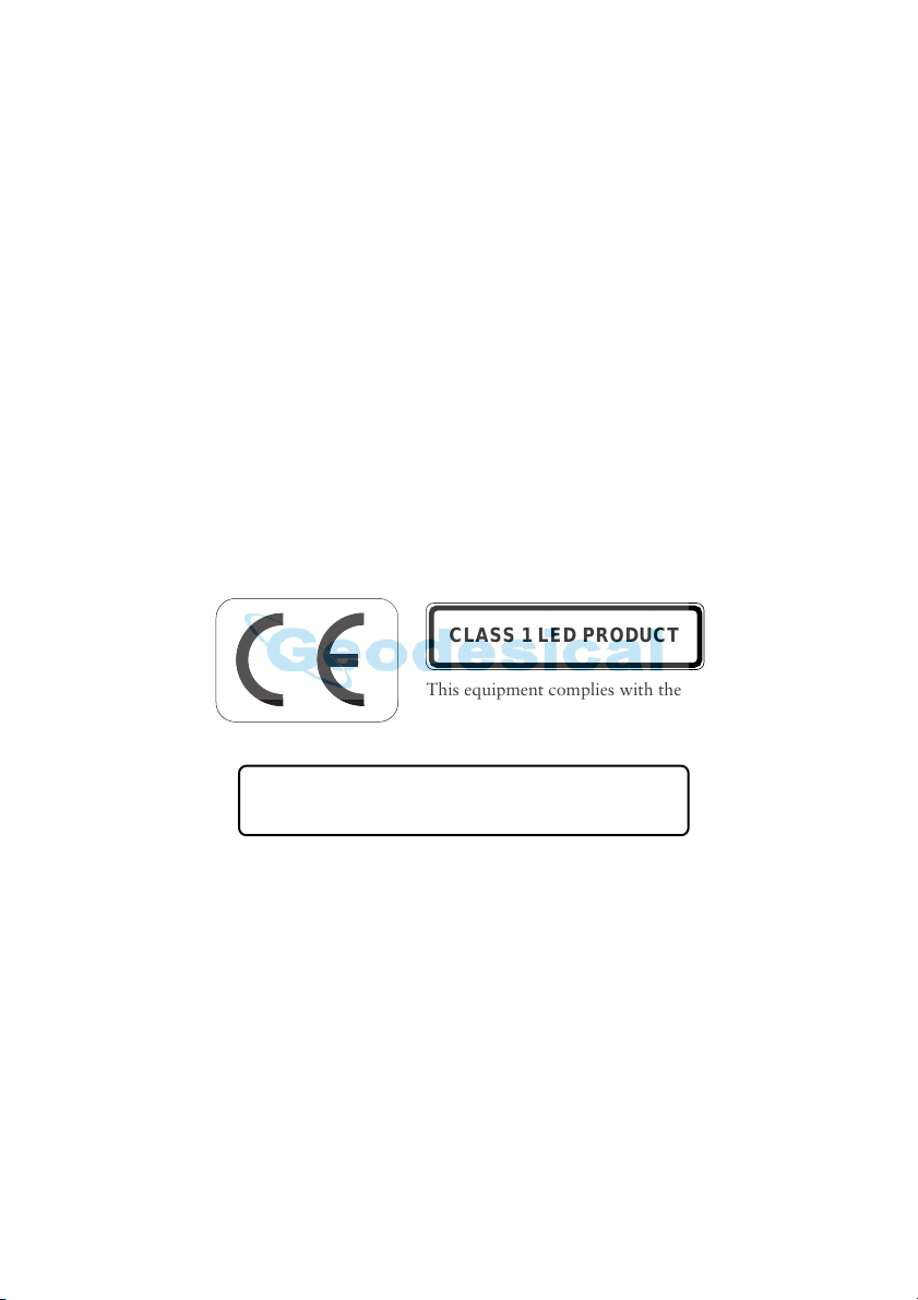
CLASS 1 LED PRODUCT
This equipment complies with the
regulations for a Class 1 LED product.
CAUTION – Use of controls or adjustments or performance
of procedures other than those specified herein
may result in hazardous LED radiation exposure
RADIO FREQUENCY INTERFERENCE
This equipment generates and uses radio frequency energy but may not cause interference to
radio and television reception. It has been type tested and found to comply with the limits for a
Class B digital device in accordance with the specification in Subpart J of Part 15 FCC Rules and
the EMC directive as stated in 89/336/EEC, which are designed to provide reasonable protection
against such interference in a residential installation. However, there is no guarantee that
interference will not occur in a particular installation. If this equipment does cause interference
to radio or television reception, which can be determined by switching the equipment off and
on, the user is encouraged to try to correct the interference by one or more of the following
measures.
— reorient the receiving antenna
— relocate the instrument with respect to the receiver
— move the instrument away from the receiver
If necessary, the user should consult the dealer or an experienced radio/television technician for
additional suggestions. The user may find the following booklet prepared by the Federal
Communications Commisions helpful: 'How To Identify And Resolve Radio-TV Interference
Problems'.
This booklet is available from the US Government Printing Office, Washington, DC 20402,
Stock No. 004-000-00345-4.

TABLE OF CONTENTS GEODIMETER SYSTEM 600
Table of Contents
Index
Welcome to Geodimeter System 600/600 Pro
About the manual
How to use this Manual
Glossary
Part 1 - Operating Instructions
Chapter 1 - Introduction
Unpacking & Inspection
Controls
The Side Cover
The Central Unit
The Control Unit
LED Information
Chapter 2 - Pre-Measurement
Office Setup
Pre-Settings
Special Settings
Test Measurements
Chapter 3 - Station Establishment
Start Procedure
Station Establishment - P20
Chapter 4 - Carrying Out A Measurement
Distance & Angle Measurement
Chapter 5 - Surveying methods
In general
Conventional Surveying with Autolock™ (only servo)
A
B
C
D
F
1.1.3
1.1.5
1.1.6
1.1.7
1.1.9
1.1.26
1.2.2
1.2.5
1.2.12
1.2.20
1.3.2
1.3.11
1.4.2
1.5.2
1.5.4

TABLE OF CONTENTS GEODIMETER SYSTEM 600
1.5.7
1.5.12
1.5.21
1.5.23
1.6.2
1.6.4
1.6.9
2.1.3
2.1.3
2.1.6
2.1.7
2.2.3
2.2.3
2.2.10
2.2.13
2.3.3
2.3.4
2.3.5
2.4.2
2.4.2
Remote Surveying
Robotic Surveying (only servo)
Eccentric Point
The RPU Menu
Chapter 6 - Important Pages
ASCII Table
General measuring hints
Info Codes
Part 2 - Technical Description "The Yellow Pages"
Chapter 1 - Angle Measurement System
Overview
The Angle Measurement Technique
Two-Face Angle Measurement
Summary of Advantages in Angle Measurement
Chapter 2 - Distance Measurement System
Overview
Distance Measurement
Remote Object Elevation (R.O.E)
UTM Scale Factor Corrected Distances
Chapter 3 - Tracklight®
Overview
How to Activate Tracklight
Changing the Bulb
Chapter 4 - Servo
Overview
Servo Controls

TABLE OF CONTENTS GEODIMETER SYSTEM 600
2.5.3
2.5.3
2.5.4
2.6.3
2.6.3
2.6.5
2.7.2
2.7.3
2.7.15
2.7.17
2.8.2
2.8.4
2.9.1
2.10.1
2.11.3
2.11.3
2.11.4
2.11.8
2.11.9
Chapter 5 - Tracker (only for servo instruments)
Overview
Tracker Operation
Controlling the tracker
Chapter 6 - Radio
Overview
Radio controls
External radio
Chapter 7 - Data Logging
Data Recording
Data Output
Data Communication
Program 54 - File Transfer
Chapter 8 - Power Supply
Batteries
Battery Charging
Chapter 9 - Definitions & Formulas
Chapter 10 - Care & Maintenance
Chapter 11 - Card Memory
Overview
Installation
Function
Memory Card
Handling hints

A
INDEX GEODIMETER SYSTEM 600
Index
Dual-axis compensator 1.3.4
Tracker 1.2.27
Card Memory Chapter 2.11
Care & maintenance 2.10.1
Central Unit 1.1.7
Coarse mode (level) 1.3.3
Collimation 1.2.20
errors 1.2.20
measurement 1.2.20
Compensator
calibration with servo 1.3.4
calibration without servo 1.3.5
On/Off 1.2.4
Computer
data output 2.7.3
data recording 2.7.2
Configuration menu 1.2.13, 1.2.17-
1.2.18
Configuration of main menu-
App.B
Contrast & viewing angle 1.1.13
Control of data registration 2.7.3
Control unit 1.1.9
functions 1.1.14-1.1.25
Controls 1.1.4
Conventional Surveying with
Autolock 1.5.3
Converter 2.8.4
Coordinates
setout 1.4.29
station 1.3.8
Cursor 1.3.3
Curvature & refraction 2.9.2
D
Data
logging 2.7.1
output 2.7.3
recording 2.7.2
A
Alphanumeric
control unit 1.1.9-1.1.10
keying in (numeric control unit)
1.1.22
Angle
measurement 1.4.1-1.4.23
measurement procedures 1.4.1-
1.4.23
measurement technique 2.1.3
measurement two-face 2.1.6,
1.4.4, 1.4.10, 1.4.14
ASCII
example 1.1.22
table 1.6.2
Atmospheric correction 1.3.6
Autolock 1.5.3-1.5.5
B
Battery
adapters 2.8.3
cables 2.8.3
chargers 2.8.4
charging 2.8.4
connection 1.2.2, 1.3.2
external 2.8.2
internal 2.8.2
status 2.8.6
Bat low 1.1.14, 2.8.5
Baud rate 2.7.10
Beam width 2.2.9
Bulb changing (Tracklight) 2.3.5
C
Cable
batteries 2.8.3
RS 232C 2.7.12
Calibration

A
INDEX GEODIMETER SYSTEM 600
Data Communication
Instrument - Computer 2.7.16
Control unit - Computer 2.7.15
Control unit - Control unit
2.7.16
Instrument - Control unit
2.7.16
Instrument - Card Memory
2.7.17
Card Memory - Computer 2.7.17
Program 54 - File transfer 2.7.18
Date/time setting 1.2.8
D-bar
accuracy 2.2.10
measurements(C1) 1.4.8, 2.2.5
measurements (C2) 1.4.10, 2.2.5
data output 2.7.5
R.O.E. 1.4.8
Decimal setting 1.2.16
Definitions & formulas 2.9.1
dH & dV explanation 1.4.5, 1.4.12,
1.4.19
Difference height correction 2.9.3
Display
contrast 1.1.13
illumination 1.1.12
tables 1.1.13, 1.2.12
viewing angle 1.1.13
Distance
measurement 2.2.3
measurement procedures 2.2.4,
2.2.5, 1.4.2, 1.4.25
Dual-axis compensator 1.3.4, 2.1.3
E
Eccentric point 1.5.20, 2.2.8
Electronic level key 1.1.21
Examples of measurement
procedures:
angle measurement P22 1.4.14
one face STD 1.4.2
two face STD 1.4.4
fast standard FSTD 1.4.7
one face D-bar 1.4.8
two face D-bar 1.4.10
tracking (tachy) 1.4.21
tracking (setting-out) 1.4.24
External
battery 2.8.2
memory 2.11.1
radio 2.6.5
F
Fast Standard measurement 1.2.18,
1.4.7, 2.2.4, 2.2.10
Fetch Station data 1.6.6
Field setup 1.3.2
File Transfer (Program 54) 2.7.18
Formulas & definitions 2.9.1
Function
key 1.1.15
list Appendix A
G
Geodimeter System 600
welcome B
software 1.1.18
Glossary of Geodimeter terms F, G
Guidelines 2.5.7
H
Horizontal
angle formula 2.1.5
angle from a line (HA_L) 1.6.7
axis (trunnion) errors 2.1.4,
1.2.20
distance correction (UTM)
2.2.13
ref.. angle setting (HAref) 1.3.7
HT_meas 1.2.17
I
Illumination of display 1.1.12

A
INDEX GEODIMETER SYSTEM 600
Info ack 1.2.17
Info codes 1.6.9
Inspection 1.1.3
Instrument
calibration 1.3.4
height 1.3.8, 2.2.10
settings 1.1.12-1.1.13
test 1.2.29
Internal
battery 1.1.7, 2.8.2
memory 2.7.20
K
Keyboard see Control unit
Keying in of alpha characters:
Numeric control unit 1.1.22
Alphanumeric control unit 1.1.23
Keyclick 1.2.18
L
Label
function key 1.1.15
recording 2.7.2
list Appendix A
Language setting 1.2.19, 1.6.3
LED information 1.1.26
Levelling of the instrument 1.3.3
Light source (Tracklight) 2.3.5
Lock on target 2.5.4
Long Range 2.2.7, App.B
M
Main menu Appendix B
Measure
angles 1.4.1-1.4.22, 2.1.1
distances 1.4.1-1.4.22, 2.2.1
Measuring hints 1.6.4
Measuring time 2.2.4-2.2.5
Memory Card 2.11.8
Menu
key 1.1.16
configuration Appendix B
Moving targets 2.2.7
N
Numeric control unit 1.1.9, 1.1.22
O
Office setup 1.2.2
One face
D-bar measurement 1.4.8, 2.2.5
STD measurement 1.4.2, 2.2.4
Output
data 2.7.3
standard 2.7.3
user defined 2.7.5
P
Packing for transport 2.10.3
Parity settings 2.7.10
Pcode 1.2.17
Power
save 1.2.18
supply 2.8.1
turn on 1.1.14, 1.2.3
unit 2.8.4
PPM
example 2.9.5
setting 1.3.6
Pre-measurement 1.2.1
Pre-settings 1.2.5
coordinate system 1.3.10
HAref 1.3.7
offset 1.3.6
PPM 1.3.6
station data 1.3.8
time & date 1.2.8
units 1.2.6
Prg_num 1.2.18
Program
additional 1.1.18
key 1.1.18-1.1.19

A
INDEX GEODIMETER SYSTEM 600
R
Radio Chapter 2.6
controls 2.6.3
external 2.6.5
Range
general 2.2.9
Recording data 2.7.2
Reboot 1.6.4
Reference Control 2.5.8
Remote Surveying 1.5.7
Remote targets Ch 2.12
RMT602 2.12.2
RMT602LR 2.12.3
RMT600TS 2.12.3
RMT Super 2.12.4
Robotic Surveying 1.5.12
R.O.E 2.2.10
RPU Menu 1.5.25
S
Search control 2.5.6
Search criteria 2.5.3
Search mode
Adv. lock 1.5.22, 2.5.6
Automatic 1.5.22, 2.5.6
Conflict 1.5.22, 2.5.6
RMT600TS 1.5.22, 2.5.6
Search routine 2.5.7
Sector control see Window control
Serial commands 2.7.11
Serial output 2.7.9
Service 2.10.3
Servo
control keys 1.1.24, 2.4.2
motion knobs 2.4.2
Set
decimals 1.2.16
display 1.2.12
HAref 1.3.7
language 1.2.19
offset 1.3.6
PPM 1.3.6
station data 1.3.7
switches 1.2.17
time & date 1.2.8
units 1.2.6
Setup
field 1.3.2
office 1.2.2
Side Cover 1.1.6
Sighting errors 2.1.6
Signal
height 1.3.8, 2.2.11
level control 1.1.13, 2.2.9
Special settings 1.2.12
Standard
fast standard FSTD 1.2.18,
1.4.7,
2.2.4, 2.2.10
measurement mode 1.4.2, 1.4.4,
2.2.4
output 2.7.4
Start procedure 1.3.2
Startup 1.3.2
Station coords. 1.3.9
Station Data 1.3.8
Station establishment
program 20 1.3.11
Surveying methods Ch. 1.5
Switches 1.2.17
T
Table 5 1.2.15
Target data test 1.2.17
Temporary horizontal angle (HA_L)
1.6.7
Test measurements 1.2.20
collimation errors 1.2.21
tilt axis errors 1.2.24
Time & date setting 1.2.8
Tracker Ch. 2.5
controlling 2.5.4
operation 2.5.3

A
INDEX GEODIMETER SYSTEM 600
Tracker coll. 1.2.27
Tracking measurement
output 2.7.4
setting out 1.4.24, 2.2.6
tacheometry 1.4.21, 2.2.6
Tracklight 2.3.1
activate 2.3.4
changing the bulb 2.3.5
Transfer files 2.7.17
Two-face measurement 2.1.6
D-bar mode 1.4.10
program 22 (servo) 1.4.14
STD (standard) mode 1.4.4
U
Unit setting 1.2.6
Unpacking 1.1.3
User defined
output 2.7.5
output example 2.7.6
display tables 1.1.13
V
VD (Vertical Distance) 2.2.11,
2.2.12
Vertical angle formula 2.1.5
View
collimation factors 1.2.21
trunnion axis factors 1.2.21
W
Warranty 2.10.3
Window control 2.5.5


Welcome to Geodimeter System 600/600 Pro
Geotronics, now Spectra Precision AB, has since the release
of Geodimeter System 400 presented a large number of
inventions within the surveying field; the tracklight, the
alpha-numeric keyboard, servo, one-person total station etc.
In 1994 Geotronics introduced the first flexible total station,
Geodimeter System 600, which made it possible for the user
to physically tailor his or her total station to his/her needs. In
1998 Spectra Precision AB introduce Geodimeter System 600
Pro which include a number of technical improvements such
as a faster CPU and faster and smoother servo positioning.
The system includes, of course, all of the features that are
typical for Geodimeter, such as servo-assisted drive
(optional), numeric or alpha-numeric control units (key-
boards), tracklight, tracker (optional), radio side cover
(optional) and RS-232C communication.
The contents of this manual are as follows:
Part 1. Operator's instructions
Chapter 1, Introduction,
describes the contents of the transport
case and the functions of the controls, control unit and display.
Chapter 2, Pre-Measurement,
explains what you should do and
think about when you are out measuring in the field, and
what parameters should be preset. This chapter also descri-
bes how to make special settings such as the number of
decimals, how to read the display, etc.
Chapter 3, Station Establishment,
contains step-by-step instruc-
tions on how to set up your instrument and then establish
the station at a known or an unknown point.
About this manual
B

Chapter 4, Carrying out a Measurement,
contains step-by-step
instructions on how to carry out distance and angle
measurements.
Chapter 5, Remote & Robotic Surveying
describes the different
measuring techniques that can be carried out with System
600/600 Pro.
Chapter 6, Important Pages,
contains important information
such as an ASCII code table, measuring hints and an Info
code list
Part 2, Technical description ("Yellow Pages")
Chapter 1, Angle Measurement System,
explains how the angle
measurement system is built up and how it functions.
Chapter 2, Distance Measurement System,
explains how distance
measurement works. It covers the system's different measu-
ring methods, accuracy, range, etc.
Chapter 3, Tracklight,
explains how Tracklight works, how it is
activated and how it is set.
Chapter 4, Servo,
explains how the Servo is controlled.
Chapter 5, Tracker (only for servo instruments),
explains how the
Tracker unit operates, how to set a search sector and also
how to use the remote target.
Chapter 6, Radio,
explains how the Radio is controlled.
Chapter 7, Data Logging,
describes how to collect and transmit
data.
Chapter 8, Power Supply,
explains the different types and
capacities of batteries and types of chargers available for
Geodimeter System 600/600 Pro.
C

D
How to use this manual
Chapter 9, Definitions & Formulas.
Chapter 10, Care & Maintenance.
Chapter 11, Card Memory.
Chapter 12, Remote Targets.
The manual for Geodimeter System 600/600 Pro is divided
into two parts:
• Part 1 gives step-by-step instructions, from unpacking
the instrument to advanced setting out.
• Part 2 provides a technical description of the main
components of the instrument. Since all pages in Part 2
are printed on yellow paper we refer to them as the
"yellow pages".
The cover also contains an appendix section, in which Ap-
pendix A is a complete list of labels, and Appendix B is an
overview of the instrument's Main Menu.
The manual covers both instructions on how to use the
system as an ordinary total station and how to use the sys-
tem for remote or robotic surveying. When using the system
for remote or robotic surveying you control the measurement
from the measuring point with a keyboard unit, which we
call RPU (Remote Positioning Unit).
The instructions in this manual indicates the difference
between the RPU-display and the instrument-display by
using different display shapes (see next page).

General instructions (control unit attached to instrument)
Instructions for the RPU (detached control unit)
In the manual we will use the following abbreviations for
mechanical resp. servo instruments:
600s = Geodimeter System 600 Pro servo instruments
600m= Geodimeter System 600 mechanical instruments
Some instructions is only valid for instruments equipped with
servo drive (600s). These instructions are indicated by a
shaded field (see below).
If you or your colleagues have any comments about this ma-
nual, we would be grateful to hear from you. Please write to:
Spectra Precision AB
Information & Market Communication Dept.
Box 64
SE-182 11 DANDERYD
SWEDEN
E
STD P0 10:19
HA: 154.3605
VA: 106.3701
STD P0 19:12
Searching
**Servo: Rotate the instrument to C1
position by depressing the A/M key in
front for approx. 2 sec. A signal is
heard if the point is marked with a
prism…
Press in front

Glossary of terms used with Geodimeter Systems
F
A file in a Geodimeter memory device that
holds known coordinates (Pno, N, E etc.) or
Roadline data.
Aim/Measure button. Initiates a measurement
and controls search and remote measurements.
Accurate measurement with mean value calc.
These values represents the collimation errors.
When performing D-bar measurements in two
faces these errors are blanked out and do not
affect the accuracy of the measurement (HA,
VA). If the values differs a lot from 0 it is
recommended that you perform a test
measurement (MNU 5), see page 1.2.20.
Also known as Resection. Location of the total
station by measuring distance and/or angles to
2 or up to 10 points.
Fast Standard measurement, with A/M
Instrument height over the point.
A file in a Geodimeter memory device that
holds data collected in the field. This file can
consist of any data.
Entering Job file and memory unit when
designing an U.D.S. with program 40.
Length offset to measured slope distance.
The prism's length offset from the 0-constant.
Reference Object, also back sight.
Area File:
A/M-key:
D:
dH & dV
Free Station:
FSTD:
IH:
Job File:
Logon:
Offset:
Prism const:
Ref. Obj:

Glossary (cont.)
G
The register key. This stores data in the data
collector.
Remote Measuring Target. The special prism
used when performing robotic surveying (or
remote surveying with auto lock™), i.e.
carrying out one-person measurements.
Remote Object Elevation. See page 2.2.10.
Remote Positioning Unit. The rod half of the
system when performing remote or robotic
surveying.
Signal height.
Standard measurement, with A/M
Tracking measurement, automatic and
continuous measurement.
User Defined Sequence. A program designed
by the user determining what is collected, its
order of collection and how it is displayed on
the screen.
REG-key:
RMT:
R.O.E.
RPU:
SH:
STD:
TRK:
U.D.S.:
IH
SH
dELE
ELE
Point to set out

1
P
a
r
t
1
O
p
e
r
a
t
i
n
g
I
n
s
t
r
u
c
t
i
o
n
s

This manual suits for next models
1
Table of contents
Popular Analytical Instrument manuals by other brands

Olympus
Olympus IPLEX LX Series instructions

Powerfix Profi
Powerfix Profi 288019 Operation and safety notes

Spartan Tool
Spartan Tool Explorer M130 product manual

Teledyne
Teledyne 3500 Series operating instructions

Leuze electronic
Leuze electronic ODS 10 operating instructions

QZTeco
QZTeco V55 Series user manual