Paprima JET-X 2000 Operating instructions

615
Paprima Industries
Operating and Maintenance Manual for
JET-X
2000
Water Jet Tail Cutting System
PROJECT NUMBER: 615
Paprima Industries75
Guthrie
Dorval, Quebec H9P 2P1
Canada
Tel:514 422-9555
Fax:514 422-9777
E-Mail: [email protected]

JET-X 2000 Manual
615
Paprima Industries
Table of Contents
Safety Precautions......................................................................................................................1
Confidentiality .............................................................................................................................2
Accident Procedures...................................................................................................................3
Simplified System Description.....................................................................................................4
Operating the Tail Cutter.............................................................................................................6
The Zero Energy State (ZES)....................................................................................................11
Recommended Routine Inspection ...........................................................................................12
The Tail Cutting Beam ..............................................................................................................16
Troubleshooting the Tail Cutter.................................................................................................23
Motion Problems.......................................................................................................................25
Recommended Torques............................................................................................................27
The Electrical Components.......................................................................................................28
The Motion Control Section.......................................................................................................30
Setting Position Parameters......................................................................................................31
Alarm Messages.......................................................................................................................33
Motion Program Flowchart........................................................................................................35
VFD Drive Parameter Settings.....................................................Error! Bookmark not defined.

1
JET-X 2000 Manual
615
Paprima Industries
WARNING!
Denotes an operating or service procedure, or condition that can result in death or serious injury
to personnel.
CAUTION!
Denotes an operating or service procedure, or condition that can lead to system operation
impairment or equipment damage.
NOTICE
Denotes an operating or service procedure, or condition considered essential for expedient,
efficient operation and service.
WARNING!
This manual is intended for use by operators, and mechanical and electrical maintenance
personnel. Operators and maintenance specialists should become familiar with the contents of
this manual prior to any hands-on involvement.
The software program supplied by Paprima is designed to technically introduce a reasonable
number of safety interlocks as a means of avoiding accidental injury. The Purchaser’s mill
expressly agrees not to alter the software program without the written consent of Paprima
Industries Inc. PAPRIMA INDUSTRIES ASSUMES NO RESPONSIBILITY FOR INJURIES TO
OPERATING PERSONNEL RESULTING FROM UNAUTHORIZED ALTERATIONS OF THE
PAPRIMA SOFTWARE.
Whenever work is to be done on the high pressure components, ensure that a proper Zero Energy
State is obtained. Before beginning the maintenance operation, verify that the appropriate
electrical breakers and air hoses are in a zero energy state, and that these items are locked and
tagged to ensure no one unknowingly activates the system.
Safety Precautions
Paragraphs titled Warning, Caution, and Notice appear throughout this manual. The
conditions outlined by these paragraphs must be thoroughly understood and followed when
using these instructions. A definition of each follows:

2
JET-X 2000 Manual
615
Paprima Industries
Confidentiality
The information supplied with this manual is expressly written for this contract. The electronic, and
printed information contained in this document is proprietory to Paprima Industries Inc and
submitted to the purchaser under confidentiality. It may not be reproduced, transmitted, divulged
or used otherwise in whole, or in part without the written permission of Paprima Industries Inc.

3
JET-X 2000 Manual
615
Paprima Industries
WARNING!
Contact with the jet can result in death. Since the jet is next to invisible, operators or
maintenance personnel have to be extremely cautious when working in proximity of the jet
because of the risk of serious injury. Direct contact with the water jet must be avoided under
all circumstances!
Accident Procedures
In the event that a person is injured through contact with the water jet, the resulting injury may
appear insignificant and give little indication as to the extent of the injury beneath the skin and
deeper tissues. Large quantities of water may have punctured the skin, flesh and organs through a
very small hole that may not even bleed. Even though the injury may seem trivial on the surface
and the patient has no complaints, it is of great importance to arrange for a surgical examination
as quickly as possible.
Immediate hospital attention is required and medical staff must be alerted to the cause of injury.
Operators are strongly encouraged to prepare internal safety procedures by preparing an
informationcardtobe issuedtothe hospital staff engaged inthe diagnosis of the injured operator.
The following text has been endorsed bythe Employment Medical Advisory Service (EMAS) of the
Health and Safety Executive:
“This person has been involved with high-pressure water jetting at pressures up to 2070
bar with a jet velocity of up to 2000 metres per second. Please take this into account
before making your diagnosis.
Unusual infections with micro-aerophilic organisms occuring at lower temperatures have
been reported. These may be gram negative pathogens such as found in sewage.
Bacterial swabs and blood cultures may therefore be helpful.”
In remote locations where surgical examination is not immediately possible, first aid response
should be restricted to dressing the wound and observing the patient closely for the
development of complications over the next 4-5 days. The development of fever and a rising
pulse rate suggests that the injury is serious, and a proper medical examination must be
arranged immediately.
If any person, object or article is accidentally struck by the jet, this fact must be reported to the
employer’s representative.
The attached information has been compiled from the “Code of Pratice” issued by the UK
Association of High-Pressure Water Jet Contractors.

4
JET-X 2000 Manual
615
Paprima Industries
Simplified System Description
The P & I Diagram
The P & I diagram provides the reader with an overview of the complete JET-X water jet tail
cutting system. Each major component is discussed on the following pages in more detail. (Refer
to drawings at the end of this manual.)
The Control Logic
ThePLC or DCSsystem controlsthefollowing functions:
The variable frequency inverter(s), responsible for the tail cutter carriage drive speed, its
acceleration rate and its deceleration rate.
The optical absolute encoder(s) which isresponsible forthe precisepositioncontrol
of the tail cutter carriage.
Theinput/output of allother functionsmaking up the waterjet high pressure system.
The Tail Cutter Beam
The tail cutter beam consists of a rectangular section in DIN1.4404 (AISI 316L) stainless steel.
Inside of the rectangular section is a sub-assembly, consisting of the cross machine carriage, and
a power track containing flexible high pressure hoses. The internal assembly can be pulled for
easy service access without deinstallation of the outer square beam section.
The Drive System
The internal assembly consists of the tail cutter and one integral gear motor. The gear motor and
the other drive components are engineered to withstand severe operating conditions. The entire
drive assembly is easily accessible for servicing, and fully protected against the high temperatures
occurring in the dry end section. The tail cutter carriage is actuated by the gear motor and a
variable frequency inverter which controls the drive speed, acceleration and deceleration of the
jet carriage. An optical absolute encoder is coupled to the gear motor for position feedback. The
encoder is reset every time the carriage returns to the PARK position by means of a reference
beam reset switch. If the encoder finds itself in error, it will automatically shut the drive down
and send an alarm signal to the operator control panel.
The sturdy stainless steel drive chain is supported on the upper and lower chain loop. This
eliminates overstretching of the chain. Adjustment of the chain tension is done on the drive side by
sliding the drive support plate.The cross machine carriage which runs in four stainless steel
wheels in over a precision machined linear rail in stainless steel. Each wheel has fully sealed and
permanently lubricated double race bearings.

5
JET-X 2000 Manual
615
Paprima Industries
The Tail Cutter Arm Assembly
The tail cutter arm assembly is equipped with two high-pressure diamond nozzles. Each nozzle
has a small aperture, typically 0.1 - 0.125 mm.
The nozzle assembly can be adjusted in different ways. Each nozzle is held in place with a set
screw. The nozzles can pivot with the nozzle holder. Each nozzle can also slide in and out of
the nozzle holder. Finally, the entire arm assembly can be positioned closer to or further from
the dryer by loosening the socket held cap screws that hold the assembly in place, and then
sliding it within the slots provided.

6
JET-X 2000 Manual
615
Paprima Industries
Operating the Tail Cutter
The operating tasks can be performed automatically through illuminated push buttons on the
operator control panel. Each tail cutter can locate a number of pre-determined points across the
sheet width with a high degree of repeatable precision. For this reason, the end-of-travel stop
point will not be overrun, which positively avoids jamming of the drive. If the operator wishes to
modifiy the set tail width, the carriage can be moved in either direction at reduced (jog) speed
for selection of a new tailcut position. Once the carriage is in a new position, it can be set to
memory by pressing two buttons.
Operator Control Panel

7
JET-X 2000 Manual
615
Paprima Industries
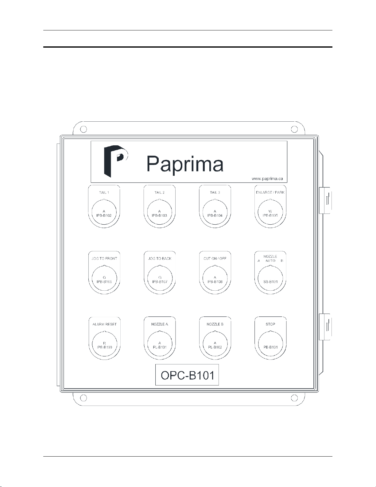
Push Buttons –POSITION
This section contains the following push buttons: TAIL 1, TAIL 2, TAIL 3, and ENLARGE /
PARK. The light of the push button is flashing when the tail cutter is travelling into position and
it turns on solid when the tail cutter is in position. Any position can be fine-tuned by pressing the
buttons JOG TO FRONT, OR JOG TO BACK. To set the last position into memory press both
buttons REPROGRAM.
Tail 1
Pressing and releasing the push button TAIL 1 moves the tail cutter carriage to its pre-set tail
position that generates the tail. At this moment one of the two jets per cutting head is coming
on.
Tail 2,3
Pressing and releasing the push buttons TAIL 2 or TAIL 3 moves the tail cutter carriage to its
pre-set tail positions, which generate a progressively wider tail. The jet remains on.
ENLARGE / PARK
Pressing and releasing the push button ENLARGE / PARK moves the tail cutter carriage over
the remaining paper width to the park position. Once in the park position the high-pressure
water jet will automatically turn off. If during tail cutting any of the three positions is selected
again, the carriages will reposition to the selected position with the jet remaining on.
Note: If the park position is on the tending side, the jet will turn off on the drive side and the jet
cutter will return at full speed to park tending side.
Push Buttons –Jog to Front / Jog to Back
Pressing either of the buttons JOG TO FRONT or JOG TO BACK allows to fine-tune the desired
new position in jog speed mode. The light for the selected tail position shuts off, and either the
JOG TO FRONT or the JOG TO BACK pushbutton light flashes rapidly indicating motion in the
selected direction of travel. To REPROGRAM the new position, press both buttons
simultaneously. Once the new position is set in memory, both pushbutton lights illuminate, and the
position light turns on solid to confirm the reprogrammed position. The carriage will now move to
the newly selected position whenever the button is pressed again.
Push Button –Cut ON / OFF
With the selector switch in the NORMAL mode, the CUT ON/OFF push button serves to turn the
jet on or off while the jet carriage is active either in a fixed tail cut position, or travelling in-between
positions. In the normal operating mode, the hydraulic power unit and the intensifiers will remain
on and the on/off command will only open and close the high pressure solenoid valve before the
tail cutting beam. If the jet is turned off in this way for more than a minute the intensifier pump and
hydraulic power unit will be automatically shut off. To indicate that the jet is on, the push button
light illuminates.

8
JET-X 2000 Manual
615
Paprima Industries
CAUTION!
To avoid frequent shock loads onto the high-pressure system, we recommend leaving the jet on
when going through the tail cutting operations.
With the selector switch in the MAINTENANCE mode, the CUT ON/OFF push button serves to
turn the jet on, while the jet nozzle is in the PARK position. This feature allows for testing of the
jet nozzles after servicing, or for routine checks, when paper is running on the machine. In the
MAINT mode, the hydraulic power unit, the intensifiers and the high-pressure solenoid valve
before the tail-cutting beam will come on and off every time the on/off command is given. When
testing the jet in MAINT mode, ensure that no persons are near the jet carriage. Serious injury
to eyes and body parts may result from contact with the high-pressure water jet!
Selector Switch –Nozzle Auto / A / B
The selector switch NOZZLE AUTO A/B normally is set to AUTO. When the switch is turned to
NOZZLE A and released, jet A is activated only. When the switch is turned to NOZZLE B and
released, jet B is activated only. The lights NOZZLE A respectively B will illuminate.
Push Button –Alarm Reset / Lamp Test
The purpose of this push button is twofold. To restart the system after an alarm, press and
release the ALARM RESET push button. This action resets the system. Then press a
POSITION push button to return to tailcutting or move the carriage to the PARK position.
For a lamp test press and hold this button for a brief time, all the illuminated push buttons
should turn on.
Mushroom Button –STOP
The STOP button is a hard wire stop for the entire tail cutting system. Pressing it stops all tail
cutting operations and hard wire interlocks the JET-X intensifiers and hydraulic power unit as
well. To restart the system after a stop, pull the STOP button out and press RESET to reset the
system. Then press a POSITION push button to move the carriage assembly to the desired
location.

9
JET-X 2000 Manual
615
Paprima Industries
NOTICE!
When in MAINT mode, all tail cutter motion is rendered inactive, i.e. all motion push buttons will
not function.
Controls on the Drive Side
On the drive side and tending side one finds a local disconnect switch for the tail cutter motor,
and a small junction box.
The local disconnect switch
Typical arrangement of motor breaker
The switch has two positions: ON and OFF.
ON
Normal operating mode.
OFF
When the carriage is in the PARK position, turn the key switch to OFF. This will disable
the operator console except for the CUT ON/OFF button to allow for nozzle testing.

10
JET-X 2000 Manual
615
Paprima Industries
The Junction Box
Illuminated light (white) - PARK
The white ENLARGE/PARK light should be on, indicating that the jet carriages are in the PARK
position.
Spring loaded switch –CUT ON / OFF
When the spring-loaded switch is set to ON and released, the jet will come on. When the spring-
loaded switch is set to OFF and released, the jet will shut off.
Spring loaded selector switch –NOZZLE A / B
First make sure that the selector switch NOZZLE AUTO A/B on the main operator panel tending
side is set to AUTO. When the switch is set to NOZZLE A and released, jet nozzle A will come
on. When the switch is set to NOZZLE B and released, jet nozzle B will come on.

11
JET-X 2000 Manual
615
Paprima Industries
WARNING!
IT IS THE FINAL RESPONSABILITY OF THE END USER TO REVIEW AND IMPLEMENT
THESE RECOMMENDED PROCEDURES WITH ITS OWN SAFETY COMMITTEE.
The Zero Energy State (ZES)
Before initiating any maintenance work, it is of crucial importance that all components of the
high-pressure water system are de-energized to Zero Energy State (ZES).
Electrical power
1) Open, lock, and tag breakers to PLC/DCS cabinet feed
Near the cutting station (tail cutter, edge trimming or slitting station)
1)
Open, lock and tag manual safety valve (see specific instructions on page 13)
2)
Close, lock and tag instrument air supply valve(s)
High-pressure pump
1) Open, lock, and tag breakers to PLC/DCS system
Please refer to instruction manual of high-pressure pump.
Having identified the components of the high-pressure water system requiring Zero Energy
State, it is now possible to proceed with a discussion of various preventative maintenance
procedures.

12
JET-X 2000 Manual
615
Paprima Industries
WARNING!
Whenever work is to be done on any equipment component, ensure that a proper Zero Energy
State is obtained. Before beginning the maintenance operation, verify that the appropriate
electrical breakers and air hoses are in a zero energy state, and that these items are locked and
tagged to ensure no one unknowingly activates the system.The software program supplied by
Paprima is designed to technically introduce a reasonable number of safety interlocks as a means
of avoiding accidental injury.
Recommended Routine Inspection
Daily Service
The following routine inspections can be undertaken by the machine operators:
Condition of the high-pressure jet
First make sure that the selector switch NOZZLE AUTO A/B on the main operator panel tending
side is set to AUTO for each carriage. Also, the white light should be on, indicating that the jet
carriages are in the PARK position.
Typical picture of a cohesive jet
Set the local disconnect switch on the junction box to OFF. This will disable the operator
console except for the CUT ON / OFF switch to allow for nozzle testing. When the switch is set
to ON, the jet will come on.
Then select NOZZLE A or B. The selected nozzle will operate.
With a flashlight observe whether the free jet is transparent (cohesive) for a length of 5 to 15
mm. Verify if the high-pressure nozzle is in good condition. The jet must be colorless. Worn
nozzles produce a white, flared jet, which also creates poorly cut edges of the sheet.

13
JET-X 2000 Manual
615
Paprima Industries
The diamond nozzles can achieve a long lifetime under continuous operation. On discontinuous
service as for tail cutters, it may be necessary to replace a nozzle prematurely due to plugging.
For details on how to change the nozzle, refer to the section “Monthly Service”.
Monthly Service
Jet carriage
Check that the linear track and the felt wiper pads of the jet nozzle carriages are well lubricated.
Application of a non-stick Molybdenum spray for lubrication of roller chains made by Target
company (Product No. 1210016), or equivalent is recommended.
Replacing the jet nozzles
First make sure that the selector switch JET AUTO A/B on the main operator panel tending side
is set to AUTO for each carriage. Also, the white light should be on, indicating that the jet
carriages are in the PARK position.
The tail cutter is equipped with a manually activated three-way isolation valve. Operate the
valves as shown below.
Three-way isolation valve under beam

14
JET-X 2000 Manual
615
Paprima Industries
CAUTION!
Before inserting the nozzle in the nozzle nut, note the correct direction of assembly! To
insert the nozzle into the nozzle nut proceed as follows: Take any paper clip and bend the
wire as shown above. Feed the wire through the nozzle nut, place the nozzle onto the wire,
and then retract the wire while following/feeding the nozzle with your clean index finger. The
nut normally is tightened manually with a socket wrench of ¾” dia. and not with a torque
wrench. (As a guideline, the recommended torque should be 25-30 ftlbs (34-40 Nm.)
Open the safety guard (where installed).
Replace the nozzle.
Close the safety guard (where installed).
Reverse the Zero Energy State procedure to return the system to its normal operating state.
Installation of hp nozzle
WARNING!
It is mandatory to open the downstream valve leading to the nozzle to release pressure to
the environment and to close the upstream valve leading to the pneumatic high-pressure
valve. Before replacing the nozzle, you must achieve a Zero Energy State. However, to speed
up the procedure, it is possible to fully close the hand valve on the pressure side and to OPEN
and lockout the valve leading to the nozzle. This measure prevents pressure buildup before
the nozzle, even in the event that the high-pressure pump is started accidentally.

15
JET-X 2000 Manual
615
Paprima Industries
Every 6-12 months
The following components should be checked and replaced if necessary:
Ensure that the hoses are not twisted and are in good condition.
Check beam reset switch.
Check encoder.
Check high-pressure hose for leaks.
Check the oil level of the drive motor gear case. If replacement is required, Paprima
recommends MOBILGEAR 636 or equivalent with a viscosity of 150 VG 220.
Check chain and chain tension on the tail cutter beam. The chain should be tensioned by
means of the spanner bolts located on the motor base plate.
Check the carriage wheels.
Check idler and drive sprocket bearings.
Check power track.
Replace the high-pressure hose.
Replace high pressure filter cartridges
Replacing the high-pressure water filter cartridges
An in-line high-pressure filter is installed in the high-pressure water line before the nozzle. Each
filter has one 35-micron element, which should be replaced once a year. To replace these filter
elements; it is necessary to remove the filter assemblies from the line. Before any servicing,
ensure that the high-pressure system is locked out. For a description of the filter, refer to
drawing ASSEMBLY FILTER 35 MICRON at the end of this manual.

16
JET-X 2000 Manual
615
Paprima Industries
The Tail Cutting Beam
Removal of the Inner Sub-Assembly
With the carriage located in the PARK position, it is possible to remove the complete
inner sub-assembly from the tending side as follows:
(Refer to installation drawing at the end of this manual.)
Remove the beam access and covers opposite tail cutter motor (when motor on
drive side).
Disassemble the jet arm.
Remove the tail cutter motor cover, and loosen the main chain tension.
Disconnect the beam reset (proximity) switch cable and housing.
Disconnect all air supply hoses, which go through the beam and the high-pressure
tubing.
Remove motor compartment (when on tending side).
Remove the inner sliding assembly-fastening bolts located on the tending and the
drive side.
The inner sliding assembly may now be pulled out.
To slide out the beam, it is necessary that the inner sliding assembly is pulled out in line with the
axis of the beam! AVOID JAMMING OF THE ASSEMBLY, WHICH CAN BE CAUSED BY
LIFTING TOO MUCH, OR BY NOT FOLLOWING WITH THE CRANE SO THAT THE CRANE
CABLES REMAIN VERTICAL TO THE BEAM SURFACE!
Maintenance to the Jet Carriage
The cross machine carriage assembly travels on double race bearings over an anodized
aluminum track that is equipped with stainless steel rails.
Top view of jet carriages with mounting plate for jet arm(s) (high pressure line removed)

17
JET-X 2000 Manual
615
Paprima Industries
Each end of the track is equipped with a sturdy stopper block, which is securely fastened to the
rail by means of four bolts. For removal of the carriage assembly, it is necessary to slide this
block off the rail at one end of the beam. The roller bearings are greased, lubricated and factory
sealed. The clearance between track and wheels on the carriage is adjusted by means of two
eccentric metric hex-bolts. Clearance should be adjusted such that there remains no looseness
of the carriage on its tracks while still allowing roller movement with a minimum of friction. After
setting the clearance by means of the center bolt with an (8) mm Allen key, tighten the
hexagonal nut (17 mm) with a torque wrench to 30 Nm. After torqueing, verify that the carriage
moves smoothly - readjust if required. The two faces of the carriage contain four spring-loaded
wiper pads. Paprima recommends that these pads are lubricated with non-stick Molybdenum
spray by Target Company (Product # 1210016).
Replacement of the Power track (hose carrier)
The power track supports and retains several stainless steel reinforced hoses. The track is
attached to the carriage support plate. Replacing any of these hoses can be done only when the
hose and power track assembly are completely removed from the machine.
Hose carrier assembly
Note that the high pressure hose can be replaced using procedures described in high pressure
hose replacement section.
To replace the power track it is necessary to remove the beam covers where the lower section
of the power track is fastened. Loosening the fasteners at the carriage and the fasteners at the
center of the beam will free the complete power track for removal.

18
JET-X 2000 Manual
615
Paprima Industries
CAUTION!
Insufficient amount of air, or removal of the cooling air will cause damage in the encoder and
high-pressure hoses! Compressed air must be supplied until the environmental temperature
near these devices is below 30C.
The Cooling System
The high temperatures associated with the dry end make cooling necessary for the high-
pressure water hoses, and the encoders. The cooling air arrives through a common header for
the high-pressure hoses to the entry couplings at the motor side of the beam and passes
through the corrugated Teflon hoses to the exit coupling located at the carriage assembly. After
passing the coupling, the air is exhausted via a silencer to atmosphere.
Replacing the High Pressure Hose
The high-pressure hose is made of a polymer core, reinforced by several layers of special steel
wire mesh. To give this material an improved life- cycle, Paprima sleeves the hose with an outer
mantle of corrugated Teflon necessitating special cooling jacket couplings for connecting the
cooling air to the outer mantle. A similar assembly is used at both ends of the cooling hose.
Ensure the carriage is in the service position and follow all lock- out procedures. Pull out the
inner sliding assembly. See instructions above.
To replace the high-pressure hose, it is necessary to open the coupling from the outer Teflon
cooling mantle. Then, loosen the socket head cap screws on the side of the high-pressure
elbow that holds the cooling coupling. Next, loosen the gland nut connecting the high-pressure
hose to the elbow body. Unscrew the small left-hand thread collar from the tip of the hose and
remove the coupling and gland nut from the hose.
Repeat the same procedure at the other end of the hose.
Table of contents
Popular Industrial Equipment manuals by other brands

steute
steute Ex STM 298 3G/D Series Mounting and wiring instructions

Terex
Terex Genie Z-45/25J Bi-Energy Operator's manual

Grundfos
Grundfos CRK Series Installation and operating instructions

Robert Kappel
Robert Kappel DSMH2-12V operating instructions

A&D
A&D LC4001A-G120 instruction manual

Jung
Jung K Series operating instructions