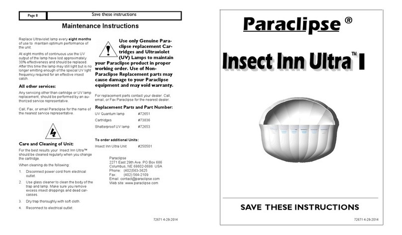
Paraclipse terminator User manual

Paraclipse ® Phone: (402)563-3625
Automated Insect Control Division Fax: (402) 564-2109
2271 29th Ave. East Web site: www.paraclipse.com
PO Box 686 www.insectinn.com
Columbus, NE 68602-0686 USA
Cartridge Maintenance:
The tacky surface of the Cartridge advances
slowly, but regularly and can remain effective
up to 60 days, depending on the volume of
insect catch.
1. When surface is no longer available or
you hear the audible beep (see page 7,
fig. 9) then you need to replace the car-
tridge (see page 6, fig. 8).
2. If the surface is filled with a heavy catch of
insects, manually advance the cartridge so
fresh surface is available (see page 6, fig.
8).
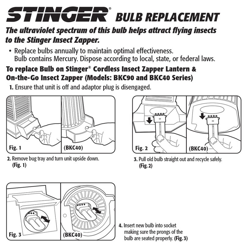
Ultraviolet light bulb replacement:
1. Disconnect unit from electri-
cal outlet.
2. Remove old bulbs.
3. Insert new bulbs and twist bulbs 90° (see
page 5, fig. 7).
Ultraviolet Reflector:
The specialized UV light reflector may become
dirty or dusty, clean with non-abrasive glass
cleaner and soft cloth.
DEAD INSECTS ARE
UNSANITARY
Maintenance Instructions
Care and Cleaning of Unit:
For the best results your Terminator™ should be
cleaned regularly when you change the cartridge.
When cleaning do the following:
1. Disconnect unit from electrical
outlet.
2. Use glass cleaner to clean the
body of the trap and bulbs. Make sure
you remove excess insect droppings and dead
carcasses.
3. Dry trap thoroughly with soft cloth.
4. Reconnect to electrical outlet.
All other services:
Any other servicing other than cartridge or UV bulb
replacement, should be performed by an author-
ized service representative.
Call or Fax Paraclipse, Inc. for the name of the
nearest service representative.
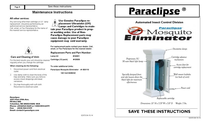
Replacement Parts:
For replacement parts contact your dealer. Call
or Fax Paraclipse, Inc. for the nearest dealer.
UV bulbs #72917
Cartridges #72926
72955-03-01-22
Save these instructions
Page 8 Paraclipse ®
Automated Insect Control Division
SAVE THESE INSTRUCTIONS
72955-03-01-22

Save these instructions
Page 2
Table of Contents
Mounting Locations Page 3
Mounting Options Page 4
Ultraviolet Bulb Insertion Page 5
Cartridge Insertion Page 6
Manual Paper Advance Page 6
Cartridge Alarm Page 7
Maintenance Page 8
IMPORTANT SAFETY INSTRUCTIONS
This symbol is intended to alert you of
the presence of dangerous voltage
within the unit’s enclosure that maybe
of sufficient magnitude to constitute a
risk of electric shock.
This symbol is intended to alert you of
the presence of important operating
and maintenance instructions accom-
panying the unit.
Caution! To reduce the risk of electric shock, observe the following:
1. Do not remove the motor enclosure. No user serviceable parts are inside.
2. This product is intended for use indoors only! Do not use where it may be ex-
posed to water or direct sunlight (including roofed but open porches).
3. Use only extension cords marked SPT-2, or equivalent. Its electrical rating must be at
least 120 V, 60 Hz, and 1 Amps. Use only extension cords which have plugs and re-
ceptacles which accept product’s plug.
4. Replace or repair damaged cords.
5. Don’t abuse cord. Never carry product by cord or yank it to disconnect it. Keep cord
from heat, oil, and sharp edges.
6. Disconnect the product from power supply when not in use, before serving, or
when changing bulbs.
7. Extension cords & devices for retaining an extension cord connection to the power
supply cord are available.
CAUTION! To avoid risk of contamination, observe the following: Dead insects are un-
sanitary. Use care in removing used cartridge.
72955-03-01-22
Terminator ™ Page 7
CARTRIDGE ALARM
Cartridge Alarm
The Terminator™ has a design feature unique
audible beep when it is time to replace the car-
tridge.
The alarm is triggered when the paper no longer
covers the hole in the top of the paper holder plate
(fig. 9). An electronic light sensor recognizes this
and begins to emit a high pitched beep.
Testing:
To test the operation of the alarm follow these
steps:
1. Lower the cartridge door.
2. Carefully remove the cartridge. The alarm
should emit an audible beeping.
3. Stop the alarm by installing a fresh cartridge.
72955-03-01-22
Fig. 9
Cartridge Alarm Sensor Hole

Save these instructions
Page 6
CARTRIDGE INSERTION & MANUAL PAPER ADVANCE
Cartridge Insertion
The tacky cartridge paper and unique motor drive
system are the heart of this state of the art insect
trap. The ease of changing the cartridge and
safety provided (because of the unsanitary dead
insects) sets your Terminator™ trap apart from the
others. The tacky cartridge can also be used as an
aid in monitoring insect types and volumes. The
side of the paper is marked every 3” with a defer-
ent thickness line. The 3” lines get thicker and
repeats every 21” as the paper advances.
1. New Unit:
Your Terminator™ is shipped with cartridge prein-
stalled. You will need to advance the cartridge so
that the tacky surface is available. (fig. 8, step 5)
2. Replacement Cartridges: (Reference fig. 8 for
all steps)
Step 1- To install a replacement cartridge lower
the cartridge door.
Step 2 - Unsnap the new halves to separate.
Slowly pull apart the cartridge halves and un-
wind paper so the cartridge halves are approxi-
mately 16” (41 cm) apart.
Step 3 - Insert cartridge halves into place. Mak-
ing certain the roll of paper is on the left side
and the right side is engaged with the motor
drive shaft.
Step 4 - Close the cartridge door. Manually
advance the tacky paper surface by simply
turning the advance knob clockwise. Turn knob
until the desired amount of tacky paper is avail-
able to catch insects.
Use the same procedure when installing a new
cartridge and advancing the paper due to heavy
insect catch.
DEAD INSECTS ARE
UNSANITARY
72955-03-01-22
Step 1
Fig. 8
Step 2
Roll of Paper
Lower Door
Separate Cartridge
Step 3
Insert Cartridge
Step 4
Rotate knob clockwise
Terminator ™ Page 3
Mounting Instructions
Your Paraclipse Terminator ™ will attract and
catch many types of insects. The trap’s superior
effectiveness is based on an insects’ desire to be
attracted to the integrally designed ultraviolet light
source and specialized attractants. Trap Place-
ment is important to optimize the performance to
the trap. Traps installed in areas without obstruc-
tion can cover up to about 8000 square feet. For
best results follow the below listed guidelines.
1. Select an area (see fig. 1) near an electrical
outlet or plan to bring an electrical
source to the area. The simplest
installation is to place the trap within
6’ (1.8m) of an electrical outlet. This
may not always be practical, it may
be necessary to wire a new source of
electricity near the ideal trap placement loca-
tion. If a new source of electricity is required
seek the help of a qualified electrician.
2. Install near room entrances. This will maxi-
mize the chances the trap will catch the in-
sects as they enter a room.
3. Install near areas of highest insect population.
4. Install in areas where room temperatures
average above 50° F. Most insects like to be
in a warm ambient temperature. Installing
your trap in a warm room will help maximize
the insect catch.
5. Install unit 4’ to 6’ (1.2 m to 1.8 m) above the
floor.
6. Do not install:
• Near competing light sources
• Near water or other damp locations
• Where traffic could possibly damage unit
• Near excessive heat sources such as ovens
or furnaces
Fig. 1
POSSIBLE TRAP
LOCATIONS
Window
Entrance
Co
unt
er
To
p
72955-03-01-22
Save these instructions
Page 4
MOUNTING OPTIONS
Types of mounting:
Your Paraclipse Terminator ™ can be mounted
two different ways, to best fit your application.
1. Ceiling mounted: (fig. 3)
Using the chain and S hooks supplied mount your
trap to ceiling supports.
Note: When mounting your Paraclipse Termi-
nator to the ceiling be certain to take into account
the trap location and suitable ceiling structure from
which to hang your trap.
Note: Due to the variety of ceiling structures no
hardware is supplied to attach to the ceiling. Be
certain suitable lag bolts, toggle bolts, eye bolts
etc. are used which will support up to 40 lbs. each.
2. Table mounting: (fig. 4)
Simply place the trap on a table in a suitable loca-
tion near an electrical outlet.
Do not install:
• Near competing light sources
• Near water or other damp locations
• Where traffic could possibly damage unit
• Near excessive heat sources such as ovens
or furnaces
Tip
Which ever mounting method you decide to go
with you will maximize the performance by incor-
porating two main concepts.
1. Place Terminator trap 4’ to 6’ (1.2 m to 1.8
m) above floor.
2. Preferred color of wall is white or a light
color if the Terminator unit has to be placed
close to wall.
Fig. 3
Fig. 4
72955-03-01-22
Terminator ™ Page 5
ULTRAVIOLET BULB INSERTION
Grill Removal and Installation: (fig. 5)
1. Removal:
Lift the grill up to a horizontal position and pull the
grill out of the mounting holes.
2. Installation:
Align the grill end rods with the two mounting
holes and push in while lowering the grill.
Bulb Protector Removal:
1.Carefully remove the cardboard from the two
bulbs. Check bulbs to make sure they are se-
cure in the light sockets. Discard the bulb pro-
tector cardboard. (fig. 6 and 7)
2. Reinstall grill.
Note: It is recommended to replace the
ultaviolet bulbs every seven months of use to
maintain optimum performance of the unit.
By seven months the UV output of the bulb has
lost approximately 30% of the effectiveness and
should be replaced. After this time the bulb may
still light but is no longer emitting enough of the
special UV light frequency required for an effective
insect catch.
Replacement bulbs: part # 72917
Troubleshooting:
If the bulbs will not light check the following:
• Make sure unit is plugged in.
• Both bulbs are inserted properly and rotated
90 degrees.
72955-03-01-22
Fig. 5
Fig. 6
Fig. 7
Other Paraclipse Insect Control Equipment manuals