PARADOX.COM
PCS265L-EI04 11/2021
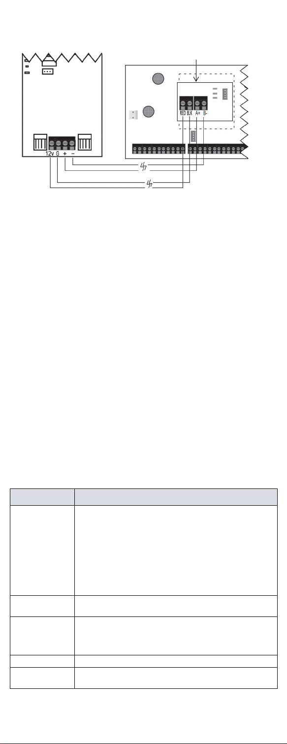
GSM Reporting (EBUS Connection)
Reporting Options
SMS Messages for Backup
Additional Programming Options
SMS Language
SMS Programming
Refer to the panel’s respective user manual for more information on
SMS Personal Reporting.
List of SMS Commands
Please note that the default password is admin.
EN Certification
The following statements apply for EN 50131 and EN 50136
certification:
• Mode of operation is pass-through
• PCS265LTE must be installed and connected to an EN approved
Grade 3 control panel
• Monitoring of the transmission network interface (Internet
connection): In case of network/interface failure, the device sends
a trouble message to the control panel which then displays it via
connected keypad(s)
• Information Security is achieved by 256-bit encrypted, supervised
communication (AES validation number 986) which prevents
unauthorized reading or modification of messages
• Substitution Security is achieved by Information Security (as stated
above), physical security (Tamper protection) and by a unique
Serial Number from each device. Messages sent to the receiving
station include the S/N in order to identify the substitution and alert
accordingly
Technical Specifications
Safety Note: This device may operate continuously in temperature of
55°C (131°F) for a maximum period of 7 days.
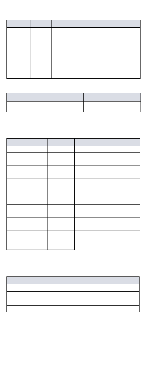
MG/SP EVO Details
[805] [2950] [1] Off + [2] Off = landline only (default)
[1] Off + [2] On = landline primary / GSM
backup (default)
[1] On + [2] Off = GSM primary / landline
backup
[1] On + [2] On = GSM only
[815] to
[817]
[3071] to
[3074]
Telephone numbers
[811] to
[812]
[3061] to
[3068]
Account numbers
Command Description
P[PASSWORD].SMS[GSM MODEM
TELEPHONE #].[IPRS-7 PASSWORD]
Used to program the
receiver’s SMS parameters
Language Value Language Value
English (default) 000 Bulgarian 016
French 001 Romanian 017
Spanish 002 Slovak 018
Italian 003 Chinese 019
Swedish 004 Serbian 020
Polish 005 Malay 021
Portuguese 006 Slovenian 022
German 007 Lithuanian 023
Turkish 008 Finnish 024
Hungarian 009 Estonian 025
Czech 010 French Canadian 026
Dutch 011 Belgian 027
Croatian 012 Latvian 028
Greek 013 Albanian 029
Hebrew 014 Macedonian 030
Russian 015
Section SMS Site Name Label
EVO
[2954] __/__/__/__/__/__/__/__/__/__/__/__/__/__/__/__
MG/SP
[780] __/__/__/__/__/__/__/__/__/__/__/__/__/__/__/__
Command Description
P[password].A[IP
address].P[port number]
Used for LTE/4G/3G/2G remote
access
P[password].IP.[call back
phone number]
Used to obtain the IP address and IP
port of the PCS265 LTE and whether
or not the “bandwidth saver” option is
being used
P[password].RESET Used to power cycle the PCS265
LTE
P[password].VOLOUT.[GSM
output volume]
Used to set the GSM output
volume; values range between 50 to
100
P[password].STATUS.[phone
number]
Used to obtain the signal strength,
signal quality, LTE/4G/3G/2G
connection status, and APN
settings of the current SIM card
P[password].
APN1.NAME.
[Access Point Name]
Used to program the SIM Card 1
APN
P[password].
APN1.USER.
[Access Point Name]
Used to program the SIM card 1 APN
User Name
P[password].
APN1.PSW.
[Access Point Name]
Used to program the SIM card 1 APN
Password
P[password].
APN1.CLEAR]
Used to clear the SIM Card 1 APN
P[password].
VAPN1.[CALL BACK PHONE
NUMBER]
Used to view the SIM Card 2 Access
Point Name information
P[password]. APN2.NAME.
[Access Point Name]
Used to program the SIM Card 2
Access Point Name
P[password].
APN2.USER.
[Access Point Name]
Used to program the SIM Card 2
Access Point User
P[password].
APN2.PSW.
[Access Point Name]
Used to program the SIM Card 2
Access Point Password
P[password].
APN2.CLEAR
Used to clear the SIM Card 2 Access
Point Name
P[password].
VAPN2.[CALL BACK PHONE
NUMBER]
Used to view the SIM Card 2 Access
Point Name information
P[password].[IP1W1/ IP1W2/
IP2W1/ IP2W2/ IP3W1/
IP3W2/
IP4W1/ IP4W2].[domain name]
Set domain name for LTE/4G/3G/2G
receiver
P[password].[IP1W1/ IP1W2/
IP2W1/ IP2W2/ IP3W1/
IP3W2/IP4W1/ IP4W2]
.CLEAR
Clear domain name for LTE/4G/3G/
2G receiver
C[user code].[ARM/
OFF].A[area number], [area
number], [area
number]TO[area number]
Arm/Disarm
P[password].---S Disable SWAN polling
(V4.10.011 and higher)
P[password].+++S Enable SWAN polling
(V4.10.011 and higher)
Specifications Description
RF Power Class 4 (2W) @ 850/1900 MHz
Class 2 (1W) @ 1800/1900 MHz
UMTS 850/1900 @ 0.25W (America)
UMTS 900/2100 @ 0.25W (Europe)
Antenna Bandwidth 5 bands, wideband
Voltage Input 12 VDC nominal
Consumption during
GPRS/GSM transmission
60 mA standby
300 mA maximum
Encryption 128-bit (AES)
SMS Protocol 7-bit (GSM: 3GPP TS 23.038/
GSM03.38)
or 16-bit (UCS2 ISO/IEC10646)
SIM Cards LTE/4G/3G
GSM (2G - n/a for North and South
America)
Humidity 0 - 90% non-condensing
Operating Temperature -20 - 50 °C (-4 to 122 °F)
Dimensions 20.8 x 7.5 x 2 cm / 8.2 x 2.9 x 0.8 in.
Certifications EN 50136-1 EN 50136-2 Grade 3
Class II
EN 50131-10 ATS Category SP5
Certification Body: Applica Test and
Certification
Warranty
The Limited Warranty Statement can be found on the website www.paradox.com/terms.
Patents
Your use of the Paradox product signifies your acceptance of these terms and
conditions. The following US patents may apply 5,886,632 and 6,215,399. Other
Canadian and international patents may apply.
©2021 Paradox Security Systems (Bahamas) Ltd. All rights reserved. Specifications
may change without prior notice.