PCS250-EI07 05/2018
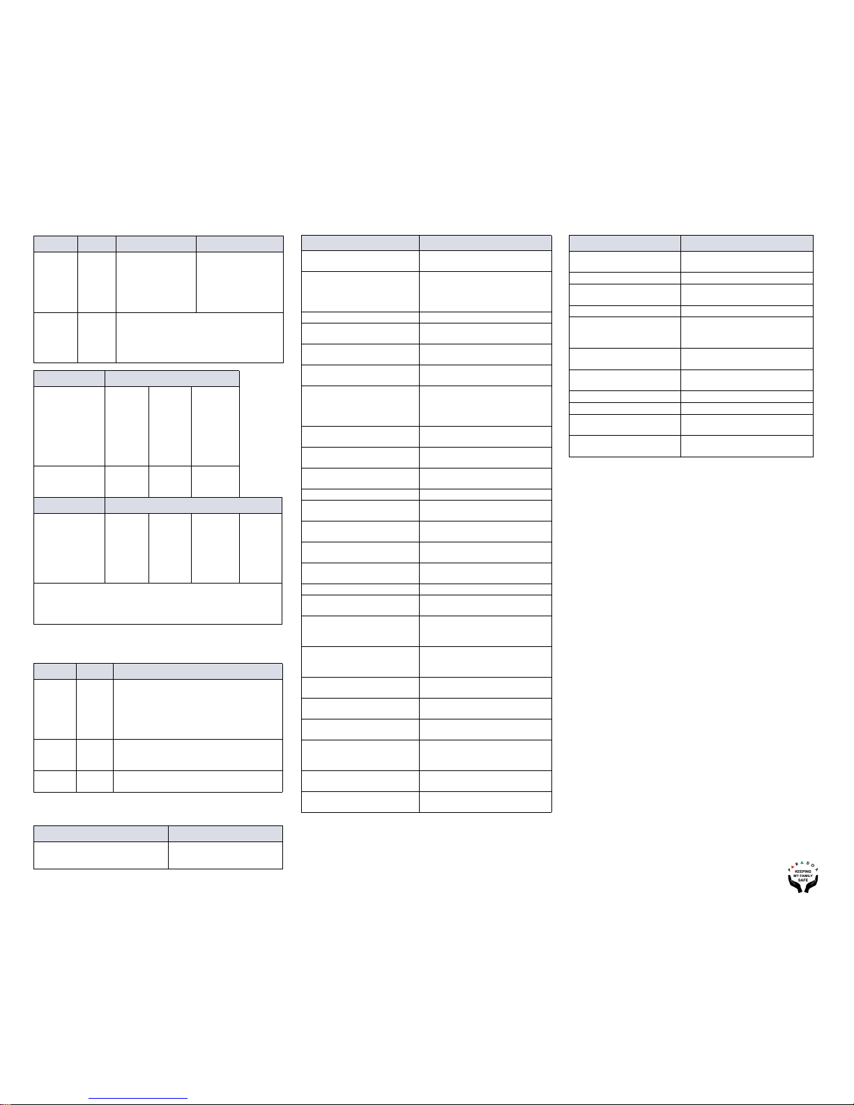
GPRS Reporting Options
GSM Reporting (EBUS Connection)
Reporting Options
SMS Messages for Backup
List of SMS Commands Technical Specifications
If you have any comments please write to us at Paradox.com/products/
feedback.
MG/SP EVO Feature Details
[918]
[919]
[2976] to
[2983]
Account / Partition
Registration
MG/SP: Sections
represent account/
partition 1 and 2
EVO: Sections
represent account /
partition 1 to 8
[806] [2975] [7] Off + [8] Off = landline only
[7] Off + [8] On = GPRS primary / landline
backup (default)
[7] On + [8] Off = landline only
[7] On+ [8] On = landline and GPRS in parallel
Receiver Settings MG/SP
Receiver #:
IP address*
IP port **
IP address WAN 2
IP port WAN2
Receiver password
Security Profile
1
[929]
[930]
[931]
[932]
[933]
[934]
2
[936]
[937]
[938]
[939]
[940]
[941]
Backup
[943]
[944]
[945]
[946]
[947]
[948]
Module registra-
tion - Press [ARM]
to register
[935] [942] [949]
Receiver Settings EVO
Receiver #:
IP address*
IP port **
IP address WAN 2
IP port WAN2
Receiver password
Security Profile
1
[2984]
2
[2986]
3
[2988]
4
[2990]
* For 1 or 2 digit numbers, add “0’s” before the digit: e.g.,
138.002.043.006
** Default = 10000
Enter [MEM] for blank space
MG/SP EVO Details
[805] [2950] [1] Off + [2] Off = landline only (default)
[1] Off + [2] On = landline primary / GSM
backup (default)
[1] On + [2] Off = GSM primary / landline
backup
[1] On + [2] On = GSM only
[815] to
[817]
[3071] to
[3074]
Telephone numbers
[811] to
[812]
[3061] to
[3068]
Account numbers
Command Description
P[PASSWORD].SMS[GSM MODEM
TELEPHONE #].[IPRS-7
PASSWORD]
Used to program the receiver’s
SMS parameters
Command Description
P[password].A[IP address].
P[port number]
Used for GPRS remote access
P[password].IP.[call back phone
number]
Used to obtain the IP address and IP
port of the PCS250 and whether or
not the “bandwidth saver” option is
being used
P[password].RESET Used to reset the PCS250
P[password].BWS.ON Used to enable bandwidth saver
mode
P[password].BWS.OFF Used to disable bandwidth saver
mode
P[password].VOLOUT.[GSM
output volume]
Used to set the GSM output volume;
values range between 50 to 100
P[password].STATUS.[phone
number]
Used to obtain the signal strength,
signal quality, GPRS connection sta-
tus, and APN settings of the current
SIM card
P[password].APN1.NAME.
[Access Point Name]
Used to program the SIM Card 1
APN
P[password].APN1.USER.
[Access Point Name]
Used to program the SIM card 1
APN User Name
P[password].APN1.PSW.
[Access Point Name]
Used to program the SIM card 1
APN Password
P[password].APN1.CLEAR Used to clear the SIM Card 1 APN
P[password].VAPN1.NAME.
[Access Point Name]
Used to view the SIM card 1 APN
P[password]. APN2.NAME.
[Access Point Name]
Used to program the SIM card 2
APN
P[password]. APN2.USER.
[Access Point Name]
Used to program the SIM card 2
APN User Name
P[password].APN2.PSW.
[Access Point Name]
Used to program the SIM card 2
APN Password
P[password].APN2.CLEAR Used to clear the SIM card 2 APN
P[password].VAPN2.[CALL
BACK PHONE NUMBER]
Used to view the SIM card 2 APN
information
P[password].[IP1W1/ IP1W2/
IP2W1/ IP2W2/ IP3W1/ IP3W2/
IP4W1/ IP4W2].[domain name]
Set domain name for GPRS receiver
P[password].[IP1W1/ IP1W2/
IP2W1/ IP2W2/ IP3W1/ IP3W2/
IP4W1/ IP4W2].CLEAR
Clear domain name for GPRS
receiver
P[password].DNS.[ip address] Set domain name server (DNS) IP
address
P[password].DNS.CLEAR Clear domain name server (DNS) IP
address
P[password].VIP.[phone num-
ber]
Get domain name server (DNS) info
C[user code].[ARM/OFF].A[area
number], [area number], [area
number]TO[area number]
Arm/Disarm
P[password].---S Disable SWAN polling
(V4.10.011 and up)
P[password].+++S Enable SWAN polling
(V4.10.011 and up)
Specifications Description
RF Power Class 4 (2W) @ 850/1900 MHz
Class 2 (1W) @ 1800/1900 MHz
Antenna Bandwidth 70 / 80 / 140 / 170 MHz
Antenna Gain <3dBi; impedance 50 ohm
Input power >2W peak power
Voltage Input 12 VDC nominal
Consumption (1.2A peak)
during GPRS/GSM transmis-
sion
100mA standby
Average 450 mA
Encryption 128-bit (MD5 and RC4) or 256-bit
(AES)
SMS Protocol 8-bit (IRA:ITU-T.50)
or 16-bit (UCS2 ISO/IEC10646)
Humidity 5 - 90% non-condensing
Weight 200 gr (7.05 oz)
Dimensions 17.2 x 9.8 x 4.4 cm
6.8 x 3.9 x 1.7 in.
Certifications Please visit Paradox.com for the lat-
est certification information
Warranty
The Limited Warranty Statement can be found on the website
www.paradox.com/terms.
Patents
Your use of the Paradox product signifies your acceptance of these terms
and conditions. The following US patents may apply 5,886,632 and
6,215,399. Other Canadian and international patents may apply.
©2018 Paradox Security Systems (Bahamas) Ltd. All rights reserved.
Specifications may change without prior notice.